
Abstract
Pneumatic soft actuators have been widely considered the safest actuation technology for use in wearable rehabilitation robots. For soft robotic gloves, researchers commonly put soft extending or bending actuators on dorsal fingers to assist hand flexion. In this research, we propose a novel pre-folded flat tube actuator (PFTA) to assist finger flex into a pre-set bending angle or contact force. The PFTA has three folds, aligned with each of the finger joint. Different from other soft actuators, the PFTA exerts bending torque directly on each finger joint without large actuator deformation. The PFTA made of heat shrink flat tube has a small profile, with low cost, easy fabrication, and high safety. When actuated, the PFTA has the tendency to unfold as well, we call this effect as unfolding flat tube actuation. This effect is characterized by a range of bending angles and input air pressures in which four distinct response regimes were observed. They are defined as shearing, collapsing, creasing, and flattening regimes. Similarly, experimental characterization of PFTAs is also conducted to evaluate the level of joint flexion assistance based on which design guidelines for robotic gloves are recommended. Finally, we build PFTAs on a soft wearable glove and demonstrate their capability in assisting the grasping operations of various object shapes.
Export citation and abstract BibTeX RIS

Original content from this work may be used under the terms of the Creative Commons Attribution 4.0 license. Any further distribution of this work must maintain attribution to the author(s) and the title of the work, journal citation and DOI.
1. Introduction
Hand as the most dexterous organ in the human body plays a vitally indispensable role in interacting with environments. However, people may partially or completely lose hand motion and failing functions caused by aging, accidents, or diseases [1–5], which significantly affects the quality of life and even make them cannot live independently. For such patients, wearable assistive gloves are promising tools to rehabilitate hands by doing repetitive tasks or assist finger motions in activities of daily living (ADL) [6, 7]. Due to the requirements of multiple degrees of freedom, compact actuator layout, safe mechanical structure, inconspicuous glove appearance, affordable cost, and so on, designing soft robotic gloves has been a research hot point in the past decade.
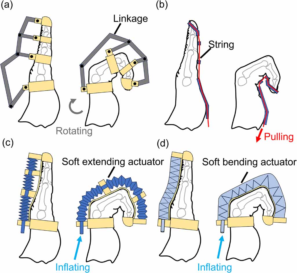
Most assistive robotic gloves can be grouped into four typical types based on the actuation principles (shown in figure 1): (a) hand exoskeletons, (b) tendon-driven robotic gloves, (c) robotic gloves with soft extending actuators, and (d) robotic gloves with soft flexion actuators [8, 9]. Hand exoskeletons (figure 1(a)) are consisted of multiple linkages and assist finger flexion by applying rotation motion on linkage near the metacarpophalangeal (MCP) directly. The hand exoskeleton, the earliest developed hand assistance robot, shows fast motion speed and robust mechanical structure in previous studies [10–13]. However, for the rigid assistive robot, misalignment is a crucial problem in designing mechanical structures and the rigid surface may hurt users during operation [14]. Besides, the bulk volume and unsightly appearance of the hand exoskeletons severely restrict their applications and reduce the desire of users. Inspired by human tendons, the biomimetic tendon-driven actuation method is widely used in designing robotic gloves as shown in figure 1(b) [15–18]. Compared with hand exoskeletons, robotic glove based on tendon-driven actuation has low weight and looks like normal gloves that could avoid stares from strangers in ADL. The control of the tendon-driven robots is easy and could be pulled by motors directly, and engineers usually use two actuated strings as agonist and antagonist actuators to control finger flexion and extension because of the unidirectional force transmission of flexible strings [19]. String/tendon driven finger flexion may still cause discomfort because the non-invasive artificial string/tendon is not aligned with the real finger tendon.

Figure 1. Existing approaches for designing robotic gloves. (a) Hand exoskeleton. (b) Tendon-driven robotic glove. (c) Robotic glove with soft extending actuator. (d) Robotic glove with soft bending actuator.
Download figure:
Standard image High-resolution imageIn contrast, soft robots are made of compliant materials such as soft polymers, fabrics, and silicone rubber elastomers [20–23]. Due to the inherent compliant structure and safe actuation, soft actuators are safe for patients. Most soft robotic gloves put soft extending (figure 1(c)) and bending actuators (figure 1(d)) on the finger back to assist finger flexion. For the soft extending actuator, due to the flexible body of the actuator, the actuator will slightly bend to adapt to the joint rotation like the soft bellow [20, 24]. However, the soft extending actuator may buckle, influencing the bending effects of the finger. For the soft bending actuator, finger flex is similar to the soft extending actuators, like the fiber-reinforced bending actuator and fabric-based pneumatic actuator [25–27]. Although there is no buckling for the soft bending actuator and they can bear a high-pressure input, users may feel uncomfortable if the bending trajectory of the soft actuator is inconsistent with the finger flexion. To increase comfortability, researchers tried to localize bending motion at joints by using segmented bending soft actuators [28, 29]. However, when the bending angle of the soft actuator is larger than the value that the joint requires, users may still feel uncomfortable.
In recent years, researchers proposed fabric-based pneumatic bending actuators with low cost, inconspicuous appearance, lightweight, and high mechanical performance [21, 30, 31]. These actuators are made of thermoplastic polyurethane (TPU)-coated fabrics that are cut by the laser machine and sealed by heat sealer or ultrasonic welding machine. Although the TPU-coated material is affordable, the fabrication process (cutting, sealing, and folding) is time-consuming.
In this study, we propose a novel pre-folded flat tube actuator (PFTA) (figure 2(a)) that is a single flat tube folded to angles aligned with each finger joint. When inflated by compressed air, each angle of the PFTA generates a localized bending torque directly on the aligned finger joint without large actuator extending and bending deformation. This means the PFTA has high actuation efficiency and response speed. The structure of the PFTA is simple, a single flat tube folded along finger joints without any complex assembly or fabrication process (figure 2(b)). For each finger joint, the PFTA is folded three times with three wrinkle sections. The material used in the PFTA is off-the-shelf ethylene vinyl acetate (EVA) heat shrink tube with extremely low cost (less than 0.3 USD for each glove).

Figure 2. Proposed robotic glove designs. (a) A single PFTA and inflation by compressed air. (b) Finger flexion assisted by PFTAs.
Download figure:
Standard image High-resolution imageThe main contributions are summarized as follows: (i) a novel PFTA is proposed to generate torque with a single flat tube structure. (ii) Experimental characterization of the unfolding flat tube actuation (UFTA) is conducted to evaluate the torque output at various air pressure inputs and bending angles. (iii) Experimental characterization of the PFTA is designed to reveal the torque output rules of the PFTA. The PFTA shows monostability when driven by compressed air which means the joint tends to bend to a critical angle, and the critical angle is programmable by adjusting the geometric parameters of the PFTA. (iv) Based on the PFTA, a soft assistive robotic glove is built together with a control system (figure 3(a)), and the practicability is verified by grasping demonstrations.
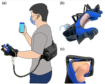
Figure 3. The soft robotic glove system based on PFTAs. (a) The portable soft robotic glove system remotely controlled by a smartphone. (b) The soft robotic glove with PFTAs. (c) Finger flexion driven by PFTA.
Download figure:
Standard image High-resolution image2. Design and modelling of PFTA
2.1. Design of the PFTA
This work focuses on the PFTA shown in figure 2(a). Different from the fabric-based pneumatic actuators with redundant folds which generate bending motion to assist finger flexion [21], each PFTA unit only has one triangular fold for driving each finger joint. For a single joint, the PFTA starts in a triangular shape, which has three wrinkles. During inflating the PFTA, the bilateral wrinkles gradually unfold to exert an actuation torque reacting against phalanges and finger joints. For fingers with three joints (except for the thumb), a single flat tube could be folded nine times to generate three UFTA folds to assist whole finger flexion (figure 3(b)). The concise structure of the PFTA further reduces the glove weight (70 g) and simplifies the manufacturing process. The actuator in this work is made of EVA heat shrink tubes inserted into a polyethylene fishing line to keep the smooth airflow. One end of the actuator, fingertip direction, is sealed using EVA hot melt adhesive, and another end is connected to a flexible silicone rubber tube sealed in the same way. Due to the similar material of the flat tube and adhesive, the PFTA shows great airtightness and can bear high-pressure input (larger than 400 kPa). PFTAs are attached to the fabric glove for rapid wear on and off. The bottom of the PFTA is glued using hot melt adhesive, and the top of the PFTA is constrained by threads to stably fix the PFTA on the glove (figure 3(c)). When actuating the glove, the height of the PFTA will decrease which reduces the visual outline of the wearable robotic glove.
2.2. UFTA
Before exploring the performance of the PFTA, the analysis of each crease, namely as the UFTA, on the folded area is required. The unfolding mechanism of the single fold was applied to design the shoulder assistive wearable robot using airtight fabric materials by previous researchers [32]. Figure 4(a) presents the mechanism of the UFTA that pressure acts upon two surfaces that are fixed along edges connected by a hinge, generating an actuation torque of the hinge. The geometric parameters of the flat tube (i.e. diameter on the inflating state D and length L) are illustrated in figure 4(a). The bending angle of the flat tube is denoted as  .
.
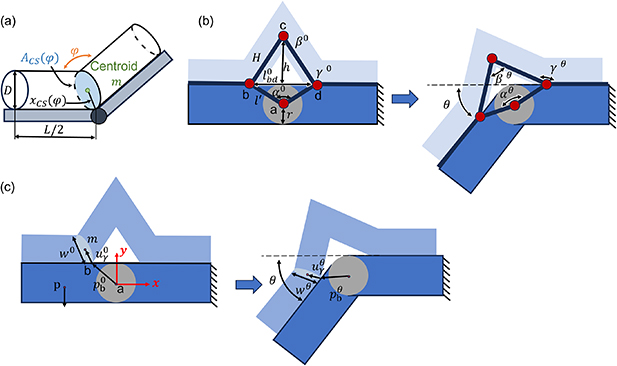
Figure 4. Modelling of pre-folded flat tube actuator (PFTA). (a) Modelling of the UFTA. (b) Kinematic modelling of the PFTA. (c) Quasistatic modelling of the PFTA.
Download figure:
Standard image High-resolution imageAt the bending angle  , the actuation force of the flat tube is generated by the fluid across the actuator cross-section which is proportional to the fluid pressure and the cross-sectional area:

where  is the first moment of area and
  is the pressure input. The actuation torque
  of the flat tube applied on the hinge can be calculated by
  , where
  is the moment arm as shown in figure 4(a). As the hinge rotates, the cross-section area of the UFTA will deform complicatedly. The cross-section area
  changing of the unfolding textile-based actuator is inferred by previous researchers [31]. Different from the actuator with the flexible textile feature, the UFTA in this study shows a slight difference and is more complicated which will be discussed in section 3.1. Anyway, the underlying principle of the UFTA force is invariable as equation (1).
2.3. Kinematic modelling of PFTA
To analyze the operating mechanism of the PFTA and provide the design guideline of the soft robotic glove, mathematical modeling of the single joint PFTA is inferred in this section. For assisting a single joint, a flat tube is folded three times to form a PFTA with three UFTA creases. As rotating the joint, the bilateral creases unfold and the top UFTA crease slightly changes to adapt to the joint motion, which could be simplified as a four-bar linkage model (figure 4(b)) to analyze the kinematic model of the PFTA. Assuming the PFTA is a symmetrical structure along the line joining points a and c, and the right linkage is fixed and the left one moves free. The lengths, angles, and positions of each linkage and joint are defined as shown in figure 4(b). At the initial state of the PFTA (i.e.  = 0
= 0 ), the design parameters are: the initial height of the fold
  and the initial distance between joints b and d
 . Meanwhile, the linkages' length
  and H are constant, where
  is the distance between joints a and b, and H is the distance between joints b and c.
  and H
and H
 . To understand the angle changing of UFTA creases when rotating joints, the angle between the linage ab and linkage ad is defined as angle
  , the top UFTA crease angle is
  , and the bilateral UFTA crease angle is
  . According to geometric relationships, when the joint rotates by angle
  , the three angles described above are:


2.4. Quasistatic modeling of the PFTA
To build the relationship between pressure input, joint rotation angle, and resistance torque, a two-dimensional quasistatic model of the PFTA is developed in this section. In the modeling, the  -axis is aligned to the direction of the fixed right linkage, and the
  -axis and coordinate origin are shown in figure 4(c).
  is defined as the basic rotation matrix, and
 ![${R^\theta } = \left[ {\begin{array}{*{20}{c}} {{\text{cos}}\theta }&{ - {\text{sin}}\theta } \\ {{\text{sin}}\theta }&{{\text{cos}}\theta } \end{array}} \right]$](https://content.cld.iop.org/journals/0964-1726/33/1/015001/revision2/smsad0f38ieqn24.gif) . At the initial state, the position of points b and p are
. At the initial state, the position of points b and p are
![$p_b^0 = {\left[ {\begin{array}{*{20}{c}} {x_b^0}&{y_b^0} \end{array}} \right]^{\text{T}}}$](https://content.cld.iop.org/journals/0964-1726/33/1/015001/revision2/smsad0f38ieqn26.gif) , and
, and ![$p_p^0 = {\left[ {\begin{array}{*{20}{c}} {x_p^0}&0 \end{array}} \right]^{\text{T}}}$](https://content.cld.iop.org/journals/0964-1726/33/1/015001/revision2/smsad0f38ieqn27.gif) , where b is the anchor point between PFTA and the left linkage, and p is the barycenter of the left linkage. When the left linkage rotates by angle
, where b is the anchor point between PFTA and the left linkage, and p is the barycenter of the left linkage. When the left linkage rotates by angle  , the position of the points b and p are:


Meanwhile, the crease angle  can be calculated based on equation (4) and defining the direction of the flat tube cross-section area in the
  -plane as a unit vector
  ,
,

The force generated by the pressure input can be simplified into a concentration force,  , acting on the centroid m. The position of the point m can be calculated by:

where  is the projected length of the flat tube cross-section area
  in the
  -plane. The direction of the force
  is presented using a unit vector
  ,
,

The force  acts about the hinge axis with a moment arm
  ,
,
When inflating the PFTA with pressure  , the bending angle of the joints can be calculated based on the equilibrium of torques:

where  is the resistance torque generated by extensors in human fingers, frictional force on joints, external force, and so on. This model is validated by comparing it with experimental values in section 3.2.2.
3. Experimental characterization
3.1. Characterization of UFTA
To explore the effects of varying the geometric parameters on the generated torque, a baseline flat tube was defined. The wall thickness of the flat tube used in this work is all 0.3 mm. The selected baseline flat tube in this section is with length L = 100 mm and diameter D = 10 mm as shown in figure 5(a). We chose this flat tube diameter because this is a universal size for most people in designing wearable robotic gloves.
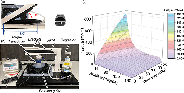
Figure 5. Experimental characterization of UFTA. (a) Flat tube parameters. (b) Experimental setup for torque measurement of the UFTA. (c) Full static characterization of the baseline actuator over all pressure and angles.
Download figure:
Standard image High-resolution image3.1.1. Experimental characterization setup of the UFTA.
An experimental testing rig was constructed to characterize the UFTA and PFTA in various bending angles and pressure inputs. The setup of the test rig is shown in figure 5(b). The flat tube is connected to a pressure source, and the pressure input is controlled by a pressure regulator (IR2000-02BG, HIGHEND, Germany). The flat tube is fixed on two brackets. The left bracket could rotate along a hinge, and another bracket is fixed. The movable bracket connects to a torque transducer (DYJN-104 2 Nm, DAYSENSOR, China) to measure the actuation torque generated by the flat tube. Meanwhile, the bottom of the torque transducer is attached to a rotation guide (RSP 125-L, Dongguan Shengling precision machinery, China). Computer interfacing was achieved using a data acquisition unit (D056, DAYSENSOR, China) to read the torque transducer. The left brackets can rotate from 0° and 180°, and the rotation axis of the brackets is aligned with the edge of the flat tube. The rotation angle of the bracket can be accurately controlled by the rotation guide.
3.1.2. UFTA torque response.
A static torque test was designed to characterize the dynamic behavior of the UFTA, and the test was conducted as follows. A flat tube was glued on brackets, and the median of the flat tube was aligned to the rotation axis of the apparatus. The angle  (figure 5(b)) between the brackets varied from 180
 to 20
to 20 . When the UFTA angle
  is less than 20
 , the extension torque is strongly influenced by the structure interference of flat tubes, which is not important in our design. To better reveal the trend of torque variation at the beginning, we tested the torque with a bending angle decreasing from 180
 to 160
 with a 5
 rate. And then, decreasing the angle
  from 160
 to 20
to 20 with a 10
 interval. For each angle, the flat tube was pressurized from 0 to 125 kPa at an interval of 12.5 kPa. Each bending angle at all pressure input conditions was conducted five times to get the mean value to release the measurement error.
The torque response of the baseline flat tube with the variant of pressure and angle is shown in figure 5(c). The generated torque surges with the increment of the pressure and the hinge rotation. When folding a flat tube to 20 , the UFTA can generate a torque of 803 mNm under a pressure of 125 kPa. A linear relationship can be observed at the beginning of the rotation between the actuation torque and pressure. However, the relationship between the torque response and the pressure input becomes complicated with the hinge rotation, which is highlighted in figure 6.
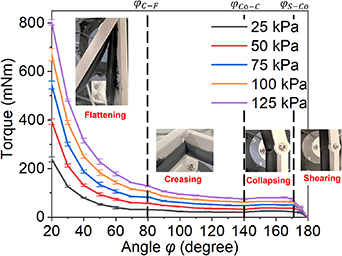
Figure 6. Experimental characterization of the isobaric torque response of the baseline UFTA over the hinge rotation.
Download figure:
Standard image High-resolution imageWhen the angle  is less than
  , nonlinear relationship happens caused by the uneven geometrical deformation of the cross-section area. Through observing the experiment test results, the deformation of the flat tube when bending the hinge can be divided into four regimes, named shearing, collapsing, creasing, and flattening regimes, respectively (figure 6). In the first regime,
  , the UFTA shears due to the low shear stiffness of the isotropic EVA thin wall. In this regime, the torque response is spring-like which is proportional to the UFTA angle ϕ as certain pressure. Since a flat tube straightens under inflation, continued bending of a flat tube causes it to collapse, which is similar to the collapsing that occurs when bending metal tubes [33]. In the collapsing regime,
  , the torque is almost in a stable state unaffected by bending angle, because of the stable structure of the collapsing holding by the inner pressure. Bending angle close to
  aggravates the collapsing which slightly decreases the torque, and the torque is minimized at the
  . Meanwhile, the double side of the flat tube tends to contact together to fill up the collapsing gap and generate a common crease named creasing regime. During the creasing regime,
  , the torque slowly increases with the hinge rotation. When
  , the UFTA toque sharpens dramatically, which is named the flattening regime. In the final regime, there is significant contact between both sides of the flat tube, and the cross-section providing torque tends to be a rectangular shape. The detailed deformation analysis of the shearing, creasing, and flattening regimes in the textile-based actuator is discussed by previous researchers [32]. However, the collapsing regime is a distinguishing phenomenon when bending an EVA tube under internal pressure. According to figure 6, applying different pressure will not change the critical angle of these regimes, which may be determined by the geometry parameters and materials of the flat tube.
3.1.3. Effect of UFTA parameters.
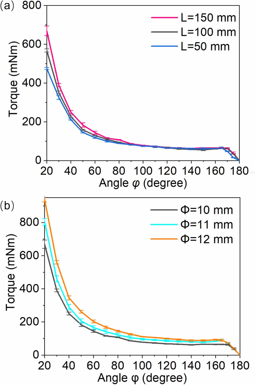
To evaluate the effect of parameters, we changed the length L and diameter D of the flat tube based on the baseline flat tube. To assess the effect of the actuator length, two flat tubes with lengths of 150 mm and 50 mm were tested under a pressure of 125 kPa (figure 7(a)). For shearing, collapsing, and creasing regimes, the flat tube length does not affect the actuation torque. The cross-section areas of those regimes were almost unaffected by flat tube length. But for the flattening regime, increasing the flat tube length increases the torque output. When designing PFTA for wearable robotic gloves, the length of the flat tube is restricted by the finger sizes.

Figure 7. Effects of the UFTA parameter on the actuation torque under an air pressure of 125 kPa. (a) Effects of the actuator length L. (b) Effects of the actuator diameter D.
Download figure:
Standard image High-resolution imageSimilarly, to estimate the effect of the flat tube diameter, two flat tubes were fabricated with diameters of 11 and 12 mm and other parameters of these flat tubes were the same as the baseline flat tube. These flat tubes were tested to compare with the baseline prototype as figure 7(b). According to equation (1), the larger the cross-section area, the higher the torque output. Therefore, in almost all regimes, the flat tube with higher diameters shows larger torque. When designing wearable robots, the diameter of the flat tube is required to match the width of human fingers. So, we are inclined to enhance the pressure input to improve the torque output.
3.2. Characterization of the PFTA
Based on the experimental characterization of the UFTA as the last section, we have an initial idea of the torque generated by each crease. In this section, we focus on evaluating the torque generated by the PFTA for one single joint.
3.2.1. Experimental characterization setup of the PFTA.
The experimental platform used to test the PFTA torque is the same as the apparatus in section 3.1. One difference is that put the PFTA on the back of the brackets. One flat tube is folded three times to form a PFTA unit, and the PFTA is geometrically symmetrical along the axis of the hinge. Several parameters define the UFTA, fold length H, PFTA length  , flat tube diameter D, etc. In the torque test, we used a baseline PFTA with a length
  = 24 mm, height H = 20 mm, diameter D = 10 mm as shown in figure 8(a).
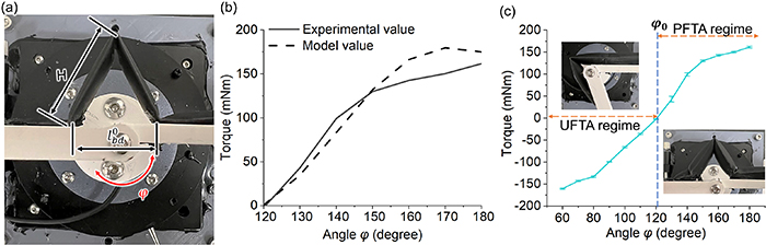
Figure 8. Experimental characterization of the PFTA. (a) Experimental setup for torque measurement of the PFTA. (b) Model validation of the PFTA. (c) Torque of the baseline PFTA.
Download figure:
Standard image High-resolution image3.2.2. PFTA torque response.
For the torque test of the PFTA, the bracket was rotated from 180 to 60
to 60 to mimic the range of motion (ROM) of human finger joints. Pressurizing the PFTA and recording the torque of the PFTA for every interval of 10
 . Figure 8(b) presents the mean flexion torque of the baseline PFTA under a pressure of 150 kPa, each position was conducted five times to get the mean value. The PFTA can generate a flexion torque of 162 mNm at a hinge angle
  of 180°. The model exhibits a consistent trend with the experimental data, and it effectively predicts the critical angle (i.e. torque output reaches zero). The torque response of the PFTA shows monostability during inflating which means the hinge trend to bend to a critical angle
  (figure 8(c)). The critical angle
  happens when the biliteral creases close to a flat state. When the hinge angle is larger than
  , the PFTA applies a positive torque to assist hinge rotation. However, when the angle is less than
  , the torque direction changes to provide a negative torque to resist hinge rotation, and the PFTA with three UFTA sections is transferred to a single UFTA section, which means only the top crease still works trending to unfold the hinge.
To evaluate the influence of the pressure input and geometry parameters, we fabricated another two PFTAs with heights H of 25 mm and 30 mm, respectively. All PFTAs were tested under the pressures of 100 kPa, 125 kPa, and 150 kPa, and the results are plotted in figure 9. The results demonstrate changing the pressure will not change the critical angle  , but change the PFTA torque value. The larger the pressure input, the PFTA has a higher capability to drive the hinge rotating to the critical angle. Meanwhile, changing the PFTA height H will change the critical angle and the torque tendency. Enhancing the height will minish the angle of the top crease, and then get a smaller critical angle. Meanwhile, changing the height will also change the cross-section shape of the bilateral creases and vary the moment arm
  , as shown in equation (10). The results show that enhancing the height will flatten the torque. PFTA heights that are too high will decrease hand dexterity and make gloves unsightly, while PFTA heights that are too low will not help users fully grip. In designing robotic gloves, the bending angle of the finger can be preprogrammed by changing the PFTA height based on the mathematical model. Overall, we suggest that the PFTA heights in the MCP and proximal interphalangeal (PIP) joints are 30 mm, and in the distal interphalangeal (DIP) joint are 25 mm.
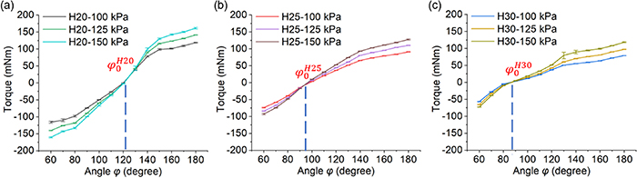
Figure 9. Experimental characterization of the torque response of the UFTAs over the hinge rotation. (a)–(c) Torque generated by the PFTA with heights of 20 mm, 25 mm, and 30 mm, respectively.
Download figure:
Standard image High-resolution image3.2.3. Dynamic response time test.
The PFTA only folds three times with a small volume change during inflation which means the PFTA has high actuation efficiency and response speed compared with those bending actuators with redundant chambers [34]. A dynamic response time test was designed to evaluate the response time of the single PFTA with a height H of 30 mm during inflating. The platform testing the response time is the same as the torque test platform, and the hinge angle  is fixed at 180
 . During the test, the pressure input was 150 kPa provided by a pressure source, and the exchange frequency of the inflating and deflating was controlled using a solenoid valve. The torque transducer sampling rate was 100 Hz, and the test was conducted under four exchange frequencies (5 Hz, 3.33 Hz, 2 Hz, and 1 Hz) as shown in figure 10. When the inflating time and deflating time are larger than 0.3 s (figure 10(b)), the PFTA can output the maximum torque at 150 kPa. For a PFTA with 3 creases, actuating the PFTA from the initial state to the maximum torque requires only 0.26 s, and the recovery time is almost 0.23 s as figure 10(d).
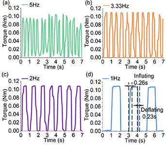
Figure 10. Dynamic response time test under different exchange frequencies. (a) 5 Hz. (b) 3.33 Hz. (c) 2 Hz. (d) 1 Hz.
Download figure:
Standard image High-resolution image3.2.4. Cyclic load test.
Different from those soft actuators with elastomer bodies [23], which may be fatigue failure due to material degradation, the PFTA deforms with slight deformation and the simple structure makes the PFTA stable. A cyclic load test was designed to verify the stability of the PFTA. The experimental setup is the same as the dynamic response test. The PFTA is bonded to brackets. Based on the results of the dynamic response test, the PFTA was inflated and deflated with an exchange frequency of 2 Hz. The torque transducer sampling rate was 10 Hz, and the PFTA was inflated more than 3000 times as shown in figure 11. The result shows that there is no obvious fatigue of the PFTA.
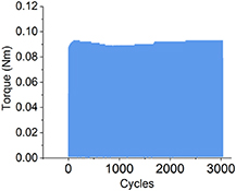
Figure 11. Cyclic load test.
Download figure:
Standard image High-resolution image3.2.5. Bending trajectory of the finger model assisted by the PFTA.
To mimic the flinger flexion assistance provided by the PFTA, an experimental platform is designed (figure 12). The size of the biomimetic finger is similar to the finger of an adult man. For each joint, a resistance torque was provided by a 180 torsional spring with an outer diameter of 10 mm and a wire diameter of 0.6 mm. The heights of each PFTA unit are 20 mm, 29 mm, and 32 mm corresponding to the DIP, PIP, and MCP joints. The result shows that the PFTA can help the finger flex up to 260° under a low air pressure of 60 (kPa), which is enough for rehabilitating hands. Meanwhile, when the pressure is larger than 60 kPa, there is no further deformation of the PFTA. This could protect users from the overflexion of fingers.
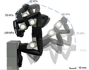
Figure 12. Bending trajectory of the finger model assisted by the PFTA.
Download figure:
Standard image High-resolution image3.2.6. Comparison between PFTA and previous actuators.
Although soft robots with various deformations have been widely studied in recent years, there is limited research on soft actuators that drive joint rotation directly excluding soft extending and bending actuators [35–38]. Table 1 shows a comparative analysis of previous soft rotary actuators and PFTAs. The weight of one PFTA unit without the air tube is only 2.4 g, which is the lightest soft actuator with the simplest structure that can drive one finger joint rotation. PFTA presents a notably high specific torque (i.e., torque per unit of actuator mass) of 67.5 mNm g−1 compared with previous works.
4. Soft robotic gloves based on the PFTA
4.1. Design of the soft robotic glove system
A control system combined with a smartphone is built to remotely control the actuation of the soft robotic glove. The control system is composed of only one mini air pump (maximum pressure 130 kPa, LH401A, BOTEICH, China), five solenoid valves, a 6-way relay module, a battery capacity, a metal button, a battery capacity indicator module, an HC-06 Bluetooth module, an Arduino Mega 2560 pro mini microcontroller, five XGZP6847A air pressure sensor modules (0–200 kPa), five RP-C7.6-ST-LF2 thin film pressure sensors (2 g–1.5 kg), and a 12 V lithium battery as shown in figure 13(a). The control system can be packaged in a 3D-printed control box (figure 13(b)). Five silicone rubber tubes connect to PFTAs on robotic glove to the solenoid valve outlets. The air pressure of each tube is monitored by a pressure sensor to control the pressure input of each PFTA actuator. The force of each fingertip is monitored by a thin film pressure sensor embedded into the fabric glove to protect users from over-actuation when grasping objects. Combining the air pressure sensors and thin film pressure sensors, the glove can assist finger grip in three grip strength levels according to daily requirements (i.e. low force, neutral force, and high force), and the close loop control diagram is shown in figure 13(c). The start and stop of the mini pump and the opening and closing of the solenoid valve are controlled by the mobile phone through the 6-way relay module using Bluetooth as communications. The control box weighs 1000 g with a compact size (150 mm 112 mm
 87 mm) that could be put on a small messenger bag (figure 13(d)).

Figure 13. Soft robotic glove system. (a) Control system. (b) Control box. (c) Close loop control diagram of the robotic glove system. (d) Soft robotic glove system.
Download figure:
Standard image High-resolution imageAs we recommended in section 3.2.2, the PFTA heights in the MCP and PIP joints are 30 mm, and in the DIP joint are 25 mm. The alignment of PFTA is aligned to the user's finger joints. And the PFTA is glued and sewn on a commercial fabric glove. Five silicone air transmission tubes are packed by a nylon braided mesh tube. The soft robotic glove system is shown in figure 13(c).
4.2. Experimental characterization of the soft robotic glove
4.2.1. Grip force test of the soft robotic glove.
Grip force assisted by the soft robotic glove was tested in this study. The experimental procedures were approved by the Human Research Ethics Committee of the University of Hong Kong with number EA1903040. We have the informed written consent of the participant.
During the test, a healthy subject wore the soft robotic glove and kept relaxing, and the hand of this subject was only actuated by the robotic glove to grip the hand dynamometer (Vernier, USA), like figure 14(a). The grip force was tested three times to alleviate measurement error. The soft robotic glove with PFTAs can generate a maximum grip force of 6.39  0.03 N, and it takes 7.58
  0.67 s to achieve the maximum grip force.

Figure 14. Grip force test of the soft robotic glove. (a) Grip force test. (b) Test result.
Download figure:
Standard image High-resolution image4.2.2. Grasping demonstration of the soft robotic glove.
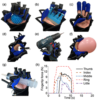
The soft robotic glove can help patients with hand disabilities such as stroke victims in rehabilitation by combining some rehabilitation equipment. Tactile stimulation can provide sensory input that engages the patient's attention and orients the individual to the paretic limb [39]. The soft robotic glove can help users grasp the soft spiky massage ball (figure 15(a)) to improve the rehabilitation effect. Besides, five fingers can move independently, and combining the hand exerciser (figure 15(b)) can help user train their finger force. Thumb opposition motions are common rehabilitation exercises for hand function recovery, which are used as an intervention that enhances the ROM and dexterity of fingers. The glove can assist users to do the finger opposition exercises as figure 15(c).
Figure 15. Grasping demonstration of the soft robotic glove. (a)–(c) Hand rehabilitation using the soft robotic glove. (d)–(f) Assisting hand functions in ADL using the soft robotic glove. (g) Grasping a cylinder. (h) Signals of thin film pressure sensors when grasping a cylinder.
Download figure:
Standard image High-resolution image
The glove can be used to assist people with weak hands (e.g. the elderly with high-level sarcopenia) in ADL. Figure 15(d) presents a pinch motion when the thumb and index finger are actuated. Due to the inherent compliance of the PFTA, the glove can grip irregular objects (figure 15(e)) without complex control algorithms, which also protects users and the grasping targets (figure 15(f)). Figures 15(g) and (h) present fingertip forces of five fingers (i.e. the signal of thin film pressure sensor) when grasping a cylinder with a diameter of 43 mm. The details of the grasping demonstration and PFTA motions can be found in the supplementary movie.
5. Conclusion and discussion
This study proposes a novel PFTA for robotic gloves using a simple mechanical structure and affordable flat tube material. The PFTA directly applies torque on each assisted joint without large deformation. To better understand the mechanism of the PFTA, one PFTA unit is divided into three UFTA sections. Design, modeling, and characterization of PFTA and UFTA are conducted in this research. The PFTA can generate a torque of 162 mNm on 0.3 s for each joint when the finger is extended. The experimental data shows the PFTA has monostability during inflating that trend to bend the joint to a critical angle which angle is programmable by adjusting the height of PFTA. The monostability enables the hand robot safer avoiding hurt to the human hand due to excessive deformation of the actuator. A soft robotic glove system that could independently drive five fingers is developed that verifies the practicability of the PFTA. Table 2 shows the comparison of four classic robotic gloves based on different actuation principles mentioned in figure 1 with the soft robotic glove based on PFTAs. The PFTA with lightweight can help users fully grip their hands under a low-pressure input, which greatly reduces the burden on the patients as only pump with smaller power is needed.
Table 2. Comparison between the proposed glove and previous gloves.
| Actuation principle | Exoskeleton [11] | Tendon-driven [16] | Soft extending actuator [20] | Soft bending actuator [24] | Our work (PFTA) |
|---|---|---|---|---|---|
| Glove weight | 500 g# | 104 g | 95 g | 207 g | 70 g |
| Actuated fingers | 5 | 3 | 5 (Independently control) | 5 (Independently control) | 5 (Independently control) |
| Actuation | Motor, linkage | Motor, cable | Pump (240 kPa) | Pump (250 kPa) | Pump (130 kPa) |
| Maximum assisting angle | 142 degrees | 164.5 degrees | 270 degrees | 148 degrees | 260 degrees |
| Grip strength | 94.61 N | 20.4 N* | / | / | 6.4 N |
| Size of glove | Bulky (>30 mm) | Inconspicuous | Moderate (<30 mm) | Moderate (<30 mm) | Moderate (<30 mm) |
Note: 1. The grip strength of different gloves cannot compare to each other directly because of the different hand gestures and instruments, and * means the grasp force of the glove are tested with the active force provided by participants with tetraplegia and the glove simultaneously.2.# means the hand exoskeleton and actuation system are integrated together and wore on the forearm.
There are some limitations and potential development space for the robotic glove and PFTA. Firstly, all modeling, experimental characterization, and glove design in this study are in one condition the PFTA folds are aligned to all joints. Although the misalignment will not hurt users which is different from the rigid hand exoskeletons, the effects of the misalignment will be explored in the future study. In addition, the simple structure and available flat tube material make the fabrication of the robotic glove theoretically fast and convenient. The PFTA has a strong potential to be easily customized for each patient, and the rapid customization process of the robotic glove will be built in the next research. Finally, the flat tube used in this study is EVA heat shrink tubes. Different materials, such as silicone rubber elastomer or TPU flat tubes, to fabricate the PFTA can be selected and tested which may contribute to a better mechanical performance.
Acknowledgments
The work described in this paper was fully supported by a grant from the Research Grants Council of the Hong Kong Special Administrative Region, China (Project No. [T42-717/20-R]).
Data availability statement
All data that support the findings of this study are included within the article (and any supplementary files).
Conflict of interest
There are no conflicts of interest to declare.
Author contributions
Hao Liu: Conceptualization, Methodology, Investigation, Data curation, Visualization, Formal analysis, Writing-original draft. Changchun Wu: Formal analysis, Software. Senyuan Lin: Software, Formal analysis. Yonghua Chen: Conceptualization, Supervision, Project administration, Resources, Funding acquisition, Writing-review& editing.
Supplementary data (9.4 MB MP4)