
Abstract
Magnetoelectric (ME) composites inherently convert magnetic energy to electrical energy and vice-versa, making them a viable technology in wireless energy transfer (WET) applications. This article focuses on identifying the optimal configuration for achieving relatively high ME power conversion efficiency in a fully ME-based transmitter/receiver composite system. Two configurations of ME composites, one in concentric composite rings and the other in layered laminate formation, have been fabricated and used alternately as transmitters and receivers. The influence of three important parameters has been experimentally studied and reported, including the effect of (1) the magnetization state of the magnetostrictive components and (2) the relative orientation of and (3) the separation distance between the transmitter and the receiver. It has been found that a higher energy conversion efficiency is obtained in a configuration where the laminated plate was used as the transmitter while the ring composites acted as the receiver. Furthermore, the location and alignment of the receiver significantly influence the output transferred power. Lastly, the distance between the transmitter and the receiver has been observed to have an exponential inverse influence on the performance of the investigated WET system. These results have been deciphered by experimentally generating horizontal and vertical magnetic field mapping around the composite systems and capacitance measurement of the piezoelectric element. Thus, this article presents a detailed study of the parameters and their influence on the performance of the ME-based WET technology, which would be extremely useful in designing and optimizing devices based on this technology.
Export citation and abstract BibTeX RIS

Original content from this work may be used under the terms of the Creative Commons Attribution 4.0 license. Any further distribution of this work must maintain attribution to the author(s) and the title of the work, journal citation and DOI.
1. Introduction
As electronic devices become more developed and complex, so do the technology and mechanisms that drive them. With advancements in science, many traditional technologies have already begun paradigm shifts to using new systems that enable more powerful and capable applications. A powerful technology that has undergone multiple transformational evolutions is wireless energy transfer (WET) to extend the range of applications [1–3]. From the induction-based mechanism first demonstrated by Nicola Tesla over a 100 years ago, many new WET mechanisms and classifications have since been introduced. Hence, the motivation leading to this research stems from advancing the state-of-the-art in WET relying solely on magnetoelectric (ME) composites to evade some of the common issues with existing wireless transfer technologies, as discussed later [4, 5].
WET technologies can be classified into three categories as near-field (or non-radiative), mid-field, and far-field (radiative) technologies based on the separation distance between the transmitter (Tx) and the receiver (Rx) components [6]. Categorizing the proximity between the transmitting and receiving elements is defined in terms of the wavelength of the transmitted energy, where far-field methods operate at distances multiple folds of the wavelength. More precisely, the distance between the transmitter and the receiver should be less than 100 mm for near-field energy transfer, between 100 and 500 mm for mid-field, and more than 500 mm for far-field WET technologies [7]. The WET technologies employ electromagnetic (EM) radiation or non-electromagnetic ways, e.g. acoustic vibrations, for energy transfer. Near-field WET technologies are more common than their far-field counterparts in everyday applications, ranging from charging consumer goods electronics to powering modes of transportation [8–10]. Generally, near-field, or non-radiative technology can be bidirectional, and the frequency is controllable; however, the efficiency losses are proportional to the inverse-cube of the distance travelled. Near-field technologies use inductive, capacitive, acoustic, or magnetodynamic coupling mechanisms to transfer energy wirelessly. Inductive WET (IWET), the oldest form of WET, uses coils to bidirectionally convert electrical current and magnetic flux to achieve power transfer efficiencies ranging from 10% to 20% in practical cases and up to 90% efficiency in idealized settings [11, 12]. Capacitor-based WET (CWET) is about as old and achieves similar efficiencies as IWET, transmitting energy via electric fields by supplying AC high voltages across an array of metal plates making it less susceptible to eddy current losses [13, 14]. CWET works at radio frequencies (usually in tens of MHz) and mainly suffers from two disadvantages: high specific absorption rate values and low power transfer efficiency. While CWET requires accurate alignment of the opposing elements, it is less prone to Joule heating than IWET. The range for inductive and capacitance WET is very short, usually requiring the elements to be nearly touching for achieving practical efficiencies unless resonant frequency matching of the transmitter and receiver is employed. Conversely, acoustic WET (AWET), which uses piezoelectric elements to couple AC voltage with mechanical vibrations, takes advantage of a phased-array focusing on improving the directionality of the transmitted energy, allowing it to outperform other near-field technologies when the elements are positioned with many wavelengths of distance apart [15, 16]. However, two disadvantages of AWET are the loss of power due to acoustic impedance mismatch reflections and poor efficiency when the elements are in proximity. Magnetodynamic WET (MWET) relies on the transmitter generating an AC magnetic flux and causing a permanent magnet to rotate inside of a receiver coil [17, 18]. The MWET technology has been used for charging electric vehicles with efficiencies >90%. This mid-field technique employs a two-port network, which acts as an intermediate link between the transmitting and the receiving elements [19]. Although the MWET operates at lower frequencies (sub kHz range), the involvement of rotating parts for dual-stage energy conversion substantially hampers the efficiency of MWET as compared to the inductive-based WET discussed earlier.
Far-field or radiative technology operates in a similar frequency range as mid-field counterparts but makes use of transmitter and receiver antennas and, therefore, can be used in cases where transmission distance is orders higher than the wavelength. Common far-field WET technologies include microwave and laser beaming, both of which transmit EM radiation in the radio or optical light regions of spectra, respectively. Microwave WET can transfer energy with efficiencies close to 100% when complicated arrangements of waveguides are used [20, 21]. In application settings, such as powering helicopters, common efficiencies range from 5% to 50%, and even up to 80% efficiency at 400 kW of power has been achieved [22]. On the other hand, the efficiency of laser-based WET is limited by the light-electricity conversion of the photovoltaic receiver element. Additionally, this technology faces other complications, including attenuation from the atmosphere and health hazards to humans and animals. However, the laser-based WET is less susceptible to radio interference, and the footprint of the transmitters and receivers is smaller than their microwave-based counterparts [23]. A comparison of the current state-of-art in WET technologies is summarized in table 1 while including additional perspectives.
Table 1. Pros and Cons of current state-of-art wireless energy transfer technologies.
| Technology | Pros | Cons |
|---|---|---|
| Far-field | Little reduction in power w.r.t. distance | Requires direct line of sight |
| Laser | No radio-frequency interference | Prone to atmospheric attenuation |
| Electromagnetism | Compact size | Blinding hazard |
| Limited by photovoltaic technology | ||
| Microwave | High far-field efficiency | Requires large Tx and Rx elements |
| Electromagnetism | Low interaction with medium | |
| Near-field | Bi-directional capability | Inverse-cube losses |
| Frequency variable | ||
| Inductor | Most common | Medium dependent (Metals) |
| Magnetic flux | Easy setup | Moderate alignment dependency |
| Cheap | Can interfere with nearby electronics | |
| Capacitor | No eddy current losses | Hazardous at high power |
| Electric fields | Low weight | Heavy alignment dependency |
| Limited maximum power | ||
| Acoustic | Phase array focusing | Medium dependent (Surfaces) |
| Mechanical Vibrations | Optimal technique at mid-range | A weaker technique at short-range |
| Magnetodynamic | Less electromagnetic interference | Can only be used in low frequency |
| Magnetic flux & Permanent Magnet | Safer | Requires moving parts |
In contrast to all the previously stated WET technologies is the strain-mediated multiferroic-based wireless energy transfer (SMMWET) paradigm, the emphasis of the current research. Composite multiferroics consist of piezoelectric and magnetostrictive phases and can be omnidirectional coupling of electrical, mechanical, and magnetic energies through strain-mediated magnetoelectricity [24–26]. Applying an AC voltage across the piezoelectric phase generates strain, which is transferred to the magnetostrictive phase, radiating alternating magnetic flux [27]. A reverse operation is also possible since magnetoelectricity is a two-way cross-coupling phenomenon. Their inherent tendency to demonstrate this cross-coupling between the mechanical, magnetic, and electrical realms makes them a fascinating prospect for WET applications [28, 29]. Wireless power transfer through magnetoelectricity also offers various advantages over other technologies. Firstly, the performance of the latter is significantly dependent on the alignment of the transmitter and the receiver elements, where any mismatch adversely hampers the working of these devices [30, 31]. Although positioning is also important in ME devices, they still exhibit a low alignment dependency [32]. Secondly, the ME phenomenon provides the flexibility to transfer the power in the best-suited energy form (selective from magnetic flux, mechanical vibration, or electric potential) following the demands of the application [33]. Thirdly, most of the discussed conventional WET techniques use high-frequency waves or vibrations, which are potential health hazards, potentially posing integration challenges in biomedical applications [34]. ME composites in the millimeter scale, usually operating in a few hundred Hz to tens of kHz range, have been shown to be biocompatible and therefore offer a wider spectrum of applications [35, 36]. Notably, the frequency range is dependent on the size, constituent materials, and operating conditions. Moreover, the magneto-mechano-electrical coupling uniquely positions strain-mediated multiferroic composites that can either be used as a standalone self-sufficient system or be compatible with any of the WET technologies listed above. For example, a multiferroic-based transmitter or receiver element can be potentially mated with an opposing CWET, AWET, IWET, or MWET element. Two recent studies demonstrated such unanimous compatibility. Truong and Roundy mated an IWET transmitter with a SMMWET receiver consisting of lead-zirconate-titanate (PZT) and Galfenol, transmitting a maximum power of 9.77 mW [37], and further parametric studies on the same three-layered ME configuration with their use in biomedical implants [38]. A subsequent study focused on optimizing the geometries for enhancing the ME response with a given volume constraint [39]. However, the studies by Truong et al employed an induction ring to transfer wireless power to the ME receiver. However, the use of Helmholtz coil as a transmitter also poses certain limitations. Firstly, the coil size is significantly more than the composite size, and this causes an increase in the device size, thus hindering its miniaturization and limiting it to particular applications. Secondly, if the coil is made too small then it poses heating issues, which has a bifold disadvantage. Firstly, it reduces the life of the coil and secondly it can adversely impact when used in temperature-sensitive applications. Additionally, when the composite is remotely controlled, any misalignment between the coil and the composite will impact the ME sensor performance. This challenge can be mitigated using ME-based transmitter, whose position can be fixed with respect to the receiver. Newacheck and Youssef were the first to demonstrate a wireless power transfer of 100 µW between two strain-mediated multiferroic composites, specifically from a PZT/Terfenol-D concentric ring composite to a PZT/Terfenol-D/PZT sandwich laminate [40]. Although the earlier study by Newacheck and Youssef demonstrated a successful and significant WET using the ME transmitter and receiver combination, one of the key inferences was to match resonance peaks of the elements to have an enhanced ME output. Thus, this research aims to enable resonance matching and then further identify the configuration that yields the best power transfer efficiency.
Despite the benefits of SMMWET, it has a significant disadvantage of still being in a stage of technological infancy. Therefore, for successfully integrating this ME-based WET technology with industry and developing products and devices employing this promising approach, more studies need to be performed to identify a configuration that maximizes the output. Thus, this study focuses on the major parameters that significantly influence the performance of ME Tx/Rx-based WET devices. Specifically, this research aims to systematically and parametrically investigate the interrelationship between the configuration, orientation, and separation distances between the transmitting and receiving on the efficacy of ME composites for WET. In the following section, a detailed account of the samples used in this study is presented, including the fabrication and experimental characterization steps—subsequently, the results and the associated discussion are reported. A section is dedicated to summarizing the limitations of the current research and providing prospects for future research to overcome these challenges. Lastly, the article concludes by enumerating the conclusions and the major takeaways from this research study.
2. Experimental procedure
2.1. Sample fabrication
The two strain-mediated ME composites used as the Tx and Rx elements for the studied SMMWET system were concentric rings and laminated plate configurations, similar to the prior study [40]. Terfenol-D and PZT were used as the magnetostrictive and piezoelectric constituents, respectively. The dimensions of the samples were based on the need to accomplish resonance matching between the receiver and transmitter, as discussed earlier in the introduction. The investigated WET devices consisted of concentric rings and laminated plate configurations that were alternatively used as transmitter and receiver elements. The laminated plate comprised a Terfenol-D plate (Etrema) sandwiched between the two PZT plates using a 5 µm conductive epoxy film (Emerson & Cuming CF3350). The assembled laminated plate configuration was 5 mm × 30 mm and 2 mm thick, including magnetic, piezoelectric, and conductive adhesive. On the other hand, the concentric composite ring assembly consisted of a radially polarized PZT outer ring (APC PZT-841) and an axially aligned Terfenol-D inner ring from the same manufacturer as the plate discussed above. The dimensions of the PZT ring were 30 mm OD × 25 mm ID, while the Terfenol-D ring was 25 mm OD × 20 mm ID. The 5 mm-thick rings were assembled using conductive silver epoxy (MG Chemicals 8331), followed by curing period, as recommended by the manufacturer. The dimensions of the PZT/Terfenol-D concentric ring were fixed to match the resonance of the laminate. The new mean diameter of the concentric ring ( ) was calculated using the resonance equation for a composite ring, given as,
where,  ,
,  , and
, and  are the average density (8450 kg m−3), compliance (1.7 × 10⁻¹¹ Pa−1), and resonant frequency of the composite (set to 42 kHz). The mean diameter was then calculated to be ca. 20 mm and was fabricated by bonding the outer PZT (APC PZT-841) ring to the inner Terfenol-D ring using the silver epoxy. The remaining fabrication and curing steps are included in [40].
2.2. Characterization
To measure the WET capabilities of the SMM system, a similar experimental setup as outlined in [40] was used. In short, Tx and Rx elements were placed within a variable bias magnetic field using an electromagnet monitored by a hall sensor connected to a Gaussmeter (FW Bell 6010). The transmitter element was connected to a waveform generator (Agilent) paired with a high voltage amplifier (Trek 780) to apply an AC electric field across the PZT component of the composite acting as transmitter, while a digital oscilloscope (Tektronix DPO 2012B) monitored the input power. Finally, the power generated by the receiver element was measured using a lock-in amplifier (SRS-830). The orientation and position of the elements depended on the aspects of the current parametric study, along with the selection of which composite acts as the receiver or transmitter. The details of the configurations tested have been discussed below.
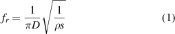
The three primary factors that govern the efficiency of ME power transmission in ME-based transmitter/receiver technology are (i) the magnetization states in the transmitter Tx and receiver Rx, (ii) the relative orientation of the transmitter and the receiver, and (iii) the separation distance between the transmitter and the receiver in various configurations. Two bias field orientations were tested, including the field along (1) the plane or (2) the axis of the ring, as well as different combinations of transmitter/receiver combinations as shown in figure 1.
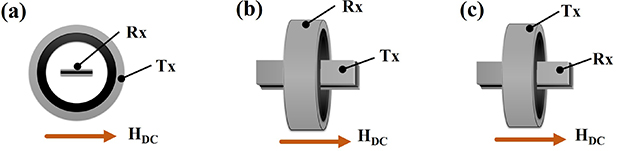
Figure 1. Configurations used in elucidating the effect of magnetic field orientation when (a) bias field parallel to the plane of the ring (Tx: Laminate; Rx: Ring), (b) bias field along the axis of the ring (Tx: Laminate; Rx: Ring), and (c) bias field along the axis of the ring (Tx: Ring, Rx: Laminate).
Download figure:
Standard image High-resolution imageSecondly, to decipher the influence of the alignment or relative orientations of the transmitter and the receiver, two sets of studies have been conducted, as depicted in figure 2. In the first set, the bias magnetic was applied diametrically along the plane of the concentric composite ring, while the Rx laminated plate was positioned parallel to the surface of the ring along (figure 1(a)) and orthogonal (figure 1(b)) to the field direction. The Tx conditions for the second set match those reported above for the first set, while the Rx was always kept normal to the surface of the ring. The Rx laminated plate element was elevated by 1 mm away from the surface of the transmitting ring. The Rx location was varied, as shown in figure 1(c), to assess the sensitivity of the transferred energy.
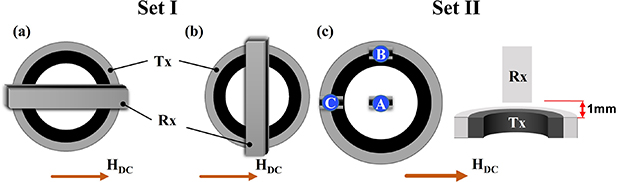
Figure 2. Relative orientation of the transmitter and receiver when (a) longitudinal axis of the plate is perpendicular to the ring axis but placed horizontally, (b) longitudinal axis of the plate is perpendicular to the ring axis but placed vertically, and (c) longitudinal axis of the plate is parallel to the ring axis but placed at different locations of the ring.
Download figure:
Standard image High-resolution imageThirdly is studying the effect of the separation distance on the efficacy of SMMWET devices with different geometries. Specifically, two sets of studies have been conducted, one where the plate is moved away from the ring along its axis (figure 3(a)) and second when the plate is moved outwards along the axis of the ring (figure 3(b)).
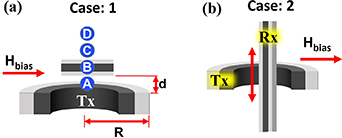
Figure 3. Influence of distance between the receiver and the transmitter when (a) plate is moved along the ring axis with their planes parallel to each other, (b) plate is moved along the axis of the ring with their axis perpendicular to each other.
Download figure:
Standard image High-resolution imageIn addition, vertical and horizontal magnetic field mapping has been experimentally generated by replacing the Rx element with a roaming search coil at various locations around the ring composite. These complimentary measurements were essential to comprehend the results, deciphering the underlying mechanism. The schematic of the locations probed for the search coils around the transmitter is shown in figure 4. The search coil consisted of 12 wire turns wrapped ca. 2 mm inner diameter hollow tube. At the outset, it is imperative to note that the term 'field' is used hereafter to refer to the magnetic field, unless otherwise explicitly stated. Additionally, the notation 'H' refers to the bias magnetic field throughout the manuscript (in both texts and figures), unless specified otherwise.
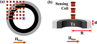
Figure 4. Movement of search coil around the transmitter/receiver composites to generate the (a) horizontal mapping of the field pattern; (b) vertical mapping of the field pattern.
Download figure:
Standard image High-resolution image3. Results and discussion
Three parametric studies were conducted to build a comprehensive understanding of the wireless power transfer system, namely, the magnetic field orientation, transmitter/receiver alignment, and separation distance. The results pertaining to these studies and their attributing factors are discussed in the following three subsections, respectively.
3.1. Effect of magnetic field orientation
Three configurations were experimentally tested with various relative orientations of the magnetic field, the transmitter, and the receiver (refer to Cases 1–3 in figure 1 and discussed section 2.2). Case 1 refers to the configuration wherein the ring is the transmitter and the plate acts as the receiver. Here, the bias magnetic field is oriented in the diametrical plane of the ring. The ME power generated by the receiver plate for various frequency and bias magnetic field combinations is depicted in the 3D plot shown in figure 5(a). The efficiency (η) in the current manuscript is defined as:

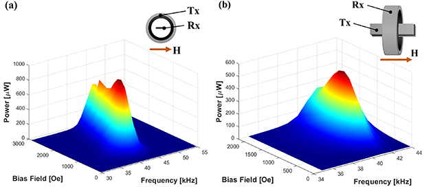
Figure 5. ME power output (µW) as a function of bias field (Oe) and frequency (kHz) when (a) bias field is in plane of the ring and perpendicular to the longitudinal axis of the plate (Tx: Ring, Rx: Plate), and (b) bias field is along the axis of the ring and parallel to the longitudinal axis of the plate (Tx: Plate, Rx: Ring).
Download figure:
Standard image High-resolution imagewhere, input power,  is calculated from the supplied voltage (V) and current (I) flowing through the Helmholtz coil. Po can be calculated using equation (3) for the reactive power of a capacitor expressed as [40]:

where, ω, C, and V refer to the operating frequency, capacitance of the piezoelectric material and ME voltage generated across the electrodes of the piezoelectric component. The generated power in the proposed WET device based on the experimental measurements was computed based on the measured output ME voltage at each operating frequency. The voltage measurements were done by the impedance-shunted electronics (lock-in amplifier), comprising a 50 Ω resistor connected in series with the sample. The power was calculated based on the source sample capacitor to highlight the underlying ME response stemming from the strain transduction between the magnetostrictive and the piezoelectric phase. However, it is imperative to note that the power can also be readily calculated based a load resistor (e.g. the input impedance of the lock-in amplifier or another load resistor) [37].
It is observed that the frequency sweep provides only one resonant peak, irrespective of the bias field value, affirming resonance matching between the transmitter and the receiver via tuning their dimensions, as discussed above. A peak power of 925 µW is recorded, corresponding to the bias field of 1.1 kOe at a resonant frequency of 42 kHz. The efficiency of ME power conversion, in this case, is 1.44%. A similar plot of the variation of ME power with respect to bias magnetic field and applied AC field frequency for Case 2 (plate as the transmitter, ring as the receiver, and applied bias magnetic field along the axis of the ring) is included in figure 5(b). The plot also shows a sole peak for a certain magnitude of applied bias magnetic field, similar to what was observed in Case 1. However, a maximum power of 528 µW was recorded at a bias magnetic field of 1.1 kOe with an AC field frequency of 41 kHz. Therefore, we observe a clear decrement in the output ME power in Case 2 compared to Case 1. However, interestingly, although the net power output decreases, the power conversion efficiency is 2.6%, i.e. an improvement of 80% over what was observed in Case 1. Since magnetoelectricity is a strain-mediated coupling effect, enabling the energy conversion from the magnetic to electrical domain or vice-versa, the efficiency of energy conversion is a more critical criterion to evaluate the effectiveness of a configuration. Therefore, the first part of the discussion is dedicated to the rationale attributed to the increased efficiency in Case 2. Four major factors have been identified to be at play here and are expected to have a decisive relationship with the output response.
Firstly, the relative orientations of the bias and AC magnetic fields has a predominant effect in realizing an enhanced ME effect. For an appreciable ME response, both the field components should be aligned in the same direction and any misalignment might adversely affect the ME output. In Case 1, since the major deformation takes place along the axis of the transmitter ring due to high height to thickness ratio, the magnetostrictive component develops poles as have been shown in figure 6(a). The major component of the AC field will be along the longitudinal axis of the plate composite, in contrast to the applied bias magnetic field in the transverse direction. Thus, the AC and DC components of magnetic fields act perpendicular to the receiver plate, thereby lowering the efficiency of power transfer. Whereas, in Case 2, the significant deformation of Terfenol-D in its longitudinal direction results in the generated magnetic flux along the same axis, as shown in figure 6(b). Consequently, the AC field due to the transmitter plate is parallel to the applied bias magnetic field, enabling the receiver ring composite to work at maximum efficiency.
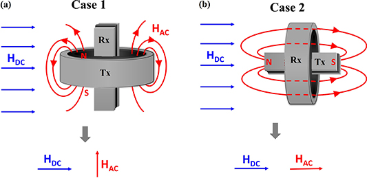
Figure 6. Pattern of AC magnetic field lines in (a) case 1 when ring is the transmitter and plate is receiver, (b) case 2 where plate is the transmitter and ring is the receiver.
Download figure:
Standard image High-resolution imageSecondly, the relative orientation of the growth direction of Terfenol-D and the applied bias magnetic field also significantly affect the ME response. Suppose the applied field is along the crystallization direction. In this scenario, the ME response is expected to be higher as lesser magnetic energy would be required for the magnetic domains to align. In other words, the slope of the magnetostriction curve will be higher, resulting in a high piezomagnetic coefficient and, therefore, a higher ME coupling coefficient. In Case 1, the direction of the applied bias magnetic field is perpendicular to the direction of crystal growth (sample's longitudinal directional in this study). In Case 2, the applied magnetic field is along the direction of crystal growth, requiring much lesser magnetic energy for the same output. Therefore, the efficiency of power conversion is significantly low in Case 1 as compared to that in Case 2.
Thirdly, the demagnetizing factors developed in the magnetostrictive components in various configurations play a crucial role in determining their magnetic behavior and, eventually, the ME response [41]. The demagnetizing factor for the cases considered above was calculated using analytical expressions. The demagnetizing factor for the magnetostrictive plate in the receiver used in Case 1 can be calculated using the expression derived by Aharoni [42] using the geometric specifications as depicted in figure 7. The demagnetizing factor is obtained as 0.116 using the above specified geometric parameters for the magnetostrictive plate. Similarly, the demagnetizing factor (K) is calculated for the ring structure placed in a magnetic field in accordance with the expression in equation (4) [43].


Figure 7. Calculation of demagnetizing factors for (a) the plate magnetostrictive material and notations used in the expression derived in [42]; and (b) the sectioned structure of the ring indicating the ring mean length Ml and cross-sectional area A.
Download figure:
Standard image High-resolution imagewhere, A and Ml correspond to the cross-sectional area and the ring mean length, respectively. The dimensions of the ring as specified in section 2.1 has been used in calculating the demagnetizing factors. The demagnetizing factor for the ring using the above expression is 0.037, which is ∼32% of that in the plate structure case. Although the calculation of demagnetizing factors for a complicated structure, such as a ring, may only provide us an approximation, the significant difference between factors obtained for the two cases can be attributed to be one of the pertinent reasons for the higher efficiency in Case 2 compared to Case 1.
Fourthly, one essential criterion that governs the ME output voltage is the magnitude of the AC magnetic field. Notably, if the ME response is expressed in the units of V cm−1. Oe, implying the output is automatically normalized by the applied AC magnetic field. However, since this study focuses on the power output (and the voltage), the AC magnetic field experienced by the samples for the same supplied input power significantly affects the net power as well as power efficiency. The sample should be completely subjected to the applied AC field for appreciable efficiency. For Case 1 in the current study, the range of the AC field generated by the ring around its periphery is not sufficient for it to encapsulate the long composite plate (as shown in figure 6(a)), resulting in a lower response from the latter that acted as the receiver. In Case 2, the AC field from the transmitter plate is expected to better encapsulate the receiver ring within its magnetic field, subjecting the latter to higher magnitudes of AC magnetic field and yielding higher ME output.
To verify the influence of the degree of encapsulation of the receiver within the AC magnetic field emanating from the ring transmitter on the considered Tx/Rx variations, a third configuration (referred to as Case 3) was tested, as depicted in the schematic figure 1(c). This configuration closely resembles Case 2 in terms of the relative positioning of Tx and Rx ME composite elements. However, the use of the two composite elements as the transmitter and the receiver has been flipped, i.e. using ring and plate as the transmitter and receiver, respectively. Figure 8 plots the output power as a function of the applied bias magnetic field and frequency for Case 3, where a peak output power of 20 µW at a bias field of 1.8 Oe and resonant frequency of 41 kHz is reported. The maximum power efficiency is merely 0.03%. Thus, it is axiomatic that this configuration drastically reduced the output power and efficiency compared to Case 2. That is, spatial encapsulation of the ME composite receiver element within the emanating magnetic field from the transmitter is of prime importance.
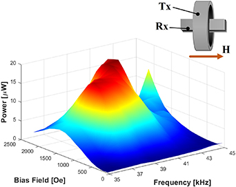
Figure 8. ME power output (µW) as a function of bias field (Oe) and frequency (kHz) when bias field is along the axis of the ring and parallel to the longitudinal axis of the plate (Tx: Ring, Rx: Plate).
Download figure:
Standard image High-resolution imageThus, all four pertinent identified factors indicate a better ME power conversion ability of the second configuration, i.e. Case 2 outperformed all other considered scenarios. Now the question at this juncture is to investigate the reason for the lower net power output in Case 2, even though the efficiency is superior. The power output from a composite structure can be calculated using equation (3). In all the conducted experiments in this study, the input voltage has been maintained constant. However, the capacitance of different PZT sample varies. Therefore, the net power output is influenced by the output ME voltage and the capacitance of the PZTs in respective configurations. The measured capacitance values for the PZT samples in plate and ring were 6.047 nF and 2.258 nF, respectively, i.e. the capacitance of the former exceeds twice that of the latter, improving the power conversion efficiency at the expense of the net power output. It then can be said that if the PZT with the same capacitance is used in both cases, the power output from Case 2 configuration will be significantly higher than Case 1. Since the prime objective of this study is to identify a more efficient configuration, Case 2 is identified as a more efficient configuration than Case 1, while elucidating design criteria that can be used in future research in developing ME-based WET with superior power outputs.
3.2. Effect of transmitter/receiver orientation
The previous section discussed the effect of the magnetization direction and the transmitter-receiver combination on the net output power and power conversion efficiency. However, the plate laminate structure was consistently placed along the axis of the composite ring in all the discussed configurations. This section seeks to identify the optimal orientation of the two composites (Tx: ring; Rx: Plate), as shown in figures 2 and 3. The result and discussion in this subsection are divided into two sets, namely Set I in which the plate composite is parallel to the plane of the ring, and Set II wherein the longitudinal axis of the plate composite is parallel to the axis of the ring. Figure 9 captures the output power as a function of the bias magnetic field and frequency of the electric field for these two cases.
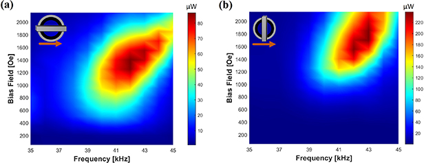
Figure 9. Variation in power output (µW) as a function of bias field (Oe) and frequency (kHz) when the bias field is (a) parallel and (b) perpendicular to the longitudinal axis of the plate.
Download figure:
Standard image High-resolution imageThe horizontal position of the plate (Set I, as shown in figure 2(a)) reported a maximum power output of 87 µW corresponding to a bias magnetic field of 1400 Oe and resonant frequency of 42 kHz at an efficiency of 0.13%. Set II (the perpendicular position of the receiver plate) generated a maximum power output of 239 µW corresponding to bias magnetic field of 1650 Oe and a resonant frequency of 43 kHz is recorded. Notably, this power is obtained at an efficiency of 0.37%. A contrasting feature is that higher efficiency is obtained in Set II but at a slightly higher bias magnetic field, where the improvement is attributed to two predominant reasons. First, the ME composite response depends on the operation mode of the PZT, where the laminated plate composite in Set I operates in d31 mode and d32 mode in Set II. Some studies have shown earlier that laminates operating in d32 mode show higher ME output than those operating in d31 mode [44, 45]. Second, the plate in the vertical configuration, when placed in a magnetic field that is perpendicular to its longitudinal axis, uniformly experiences the field across its entire area compared to the horizontal case, where the variations are high along the longitudinal axis of the plate. Thus, these factors cumulatively result in much higher power efficiency in Set II (vertical plate) compared to the horizontal position (Set I). However, as stated earlier, the vertical plate configuration shows better efficiency at a slightly higher bias magnetic field. To substantiate this result, demagnetizing factors for the receiver magnetostrictive plate are calculated to be 0.035 and 0.116 for the horizontal and vertical positions, respectively, indicating that the vertically positioned configuration requires a slightly higher bias magnetic field for attaining the maximum power conversion.
The effect of orientation when the longitudinal axis of the plate composite is along the axis of the ring has also been probed as part of this research, focusing on three different positions. The laminated plate was positioned in two locations along the periphery and one at the center (refer to figure 10(a)). The results are shown in figures 10(b)–(d). It is observed that configuration 'C' shows the highest power output compared to the other two configurations, e.g. 'A' and 'B.' Since the transmitter and receiver designation of the two ME composites remain the same across all positions, the change in their output response can be attributed to the magnitude of the DC and AC magnetic fields experienced at each sample position. Hence, spatial mapping of the emanating magnetic field has been performed to probe the variation of AC magnetic field at various locations in the first quadrant of the ring, as delineated in figure 11(a). The results of the spatial mapping are reported in figure 11(b), where the locations corresponding to 'B' and 'C' in figure 11(a) have significantly lower flux compared to location 'A.' While this is consistent with our previous results investigating the strain transduction within a Terfenol-D ring [46], it contrasts with the ME result obtained herein. Thus, the emphasis is shifted to the effect of bias magnetic field. Since the relative permeability of Terfenol-D is very high, it tends to attract a significant proportion of the applied magnetic field. This attraction and concentration of field are even higher at the top and bottom portions of the ring. This was shown by numerical simulations in our previous works conducted using COMSOL Multiphysics [47, 48]. Thus, although location 'C' experiences a lower magnitude of alternating magnetic field, it still shows a better power conversion efficiency due to receiving sufficient bias magnetic field to align Terfenol-D domains. Furthermore, this distinctly highlights the importance of the proper combination of bias and AC magnetic fields to obtain high ME output or more efficient ME power conversion efficiency.
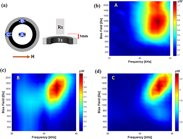
Figure 10. Alignment of plate laminate at three locations (a) along the periphery and the center of the ring and power output (µW) as a function of bias field (Oe) and frequency (kHz) at location specified as (b) point 'A', (c) point 'B', (d) point 'C' in schematic '(a)'.
Download figure:
Standard image High-resolution image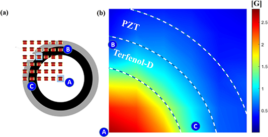
Figure 11. (a) Schematics of the mapping measurements including points in and around the ring transmitter where search coil has been used, and (b) mapping of the magnetic field obtained through search coil at the corresponding locations (Note: measurement by search coil has been performed in one quadrant due to the presence of symmetry along the two axes).
Download figure:
Standard image High-resolution image3.3. Effect of distance
Figure 12 summarizes the results elucidating the influence of separating distance between the transmitter and the receiver on the power output of the ME-based WET technology when the longitudinal axis of the plate composite is perpendicular to the axis of the ring (surfaces of ring parallel to the plate). On the other hand, figure 13 shows the output power of the same Tx/Rx configuration when the longitudinal axis of the plate is in line with the axis of the ring. For the results in figure 12, the power output has been measured when the plate was located at d/R (distance between plate and ring surfaces/radius of the ring) values of 0, 0.16, 0.32, and 0.48, denoted as 'A', 'B', 'C', and 'D' in figures 12(c)–(f). An assimilated plot for the four positions shown in figure 12(a) depicts a monotonic exponential drop in the ME power output from 250 µW to 26 µW, as the separation distance increased to 0.48 d/R ratio.

Figure 12. (a) Variation in power (µW) as a function of distance to radius ratio (d/R), (b) points 'A','B','C', and 'D' representing the distance of the plate from the ring, power variation (µW) as a function of bias field (Oe) and frequency (kHz) for (c) point A, (d) point B, (e) point C, and (f) point D.
Download figure:
Standard image High-resolution image
Figure 13. (a)–(c) Variations in power (µW) as a function of bias field (Oe) and frequency (kHz) for cases as shown in the figure; (d) cumulative plot of the variation in power with decreasing receiver Rx engagement with the transmitter Tx.
Download figure:
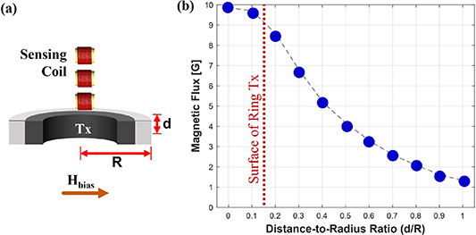
Standard image High-resolution imageFor a second case, the plate traverses vertically along the axis of the ring with its axis along coinciding with that of the ring. The results obtained for the three positions of the plate have been shown in figure 13. A similar exponential decrement was also observed, where the output power descends from 925 µW to 140 µW, as the plate is pulled out of the ring. Such a response is expected, as the magnetic field being a function of second power of distance, such that it exponentially decreases as the plate moves away from the center of the ring. In order to substantiate this hypothesis, a vertical mapping has been generated experimentally using a search coil. A plot of the variation in the magnetic flux as a function of the d/R ratio depicted in figure 14 captures this exponential decrease as the search coil moves away from the ring center outwards in a similar way as the movement of the plate composite.
Figure 14. (a) Locations of search coil along the ring axis for vertical mapping of the magnetic field, and (b) variation of Magnetic flux (G) as a function of the d/R ratio.
Download figure:
Standard image High-resolution image
Therefore, we observe in both cases that the ME power output is adversely affected or is exponentially inversely proportional to the distance between the transmitter and the receiver. Thus, it is apodictic that the distance between the transmitter and the receiver is a crucial factor, governing the output power in ME-based WET devices.
3.4. Current limitations and prospects
The current research emphasized the interrelationship between the configuration, orientation, and separation distance between ME transmitting and receiving devices as a function of electric and magnetic fields. The approach was to measure un-optimized power output via recording the voltage output of the piezoelectric electrodes, revealing limitations to the current study while motivating prospects. The limitation and prospects are enumerated below.
- 1.Since the current study focused on identifying the efficacy of ME-based WETs as a function of the configuration, orientation, and separation distance between the transmitting and the receiving elements, the power measurements were conducted at an arbitrary load resistance (impedance-shunted electronics). The findings of this study can be extended for enhancing and optimizing the power that can be harnessed by measuring the variation of output voltage with respect to various load resistance, as recently reported in [37].
- 2.The obtained ME output can be further boosted by using advanced constituent materials with higher piezoelectric and magnetostrictive coefficients, improving the ME power output. The latter can be achieved by mating ME elements with a conventional WET element, including those summarized in table 1 and [28].
- 3.Instrument and measuring errors are an integral part of any experimental scheme. However, they are marginal in the current study based on the instrumentation specification used and measured quantities. Therefore, Quantification of uncertainties [49] in measuring parameters as a result of such errors could be a meaningful extension of the current research, a study realm which has largely been untapped in the ME community.
- 4.In contrast to the methodology employed for power calculation herein, the ME output can also be estimated by formulating an equivalent circuit model and using it for determining the optimum load resistance for studied configurations.
4. Conclusion
This article focuses on parameters that lead to optimum power and enhanced power transfer efficiency in ME-based transmitters/receivers for wireless power transfer technology. The essential parameters are the magnetization state in the magnetostrictive component of composites with respect to the applied AC and bias magnetic fields, the relative orientation of the transmitter and the receiver, and the separation distance between the receiver and the transmitter elements. Laminated plates and concentric ring composite structures are interchangeably used as the transmitting and receiving elements. The maximum power transfer efficiency is observed when the plate is the transmitter and the ring is the receiver. This coincided with specific orientation when the elements are placed such that the longitudinal axis of the plate coincides with the axis of the ring. The relative alignment of AC and bias magnetic fields, poling direction of Terfenol-D with respect to the magnetic field, coverage of the receiver in the generated AC magnetic field, and the demagnetizing factors of the magnetostrictive components in the composite were identified as significant factors governing the output efficiency. Regarding the alignment, the maximum efficiency was observed in case the ring and plate faces are parallel such that the longitudinal axis of the plate is perpendicular to the axis of the ring. Lastly, the ME output was observed to show an exponential decrease with an increase in the distance between the transmitter and the receiver. Thus, this article presents a detailed experimental study into the effect of various parameters that substantially affect the output response of the ME transmitter and receiver based WET device and would be highly beneficial in designing the new age ME-based WET devices. The outcomes of this research suggest that further increase in the output efficiency can be achieved through exploration of different material phases, including magnetostrictive and piezoelectric constituents, and hybridization with other WET technologies. Finally, the current research unlocks the potential of multiscale ME-based communication and powering devices.
Acknowledgments
The authors will like to acknowledge the National Science Foundation for the funding to support this research (Contact No. EEC-1160504). The authors also acknowledge the support of the by the United States Department of Defense under Grant Agreement Nos. W911NF-14-1-0039 and W911NF1810477. The research was also supported by internal funds from San Diego State University.
Data availability statement
All data that support the findings of this study are included within the article (and any supplementary files).