

Abstract
To develop high-strength water hydraulic artificial muscle (WHAM) and ensure its reliability, the failure mechanism and the main effect factors of WHAM's strength were studied. WHAM's failure modes consist of end fitting slipping out, fibre sleeve loosening, the end of rubber tube breaking, rubber tube coming out from fibre sleeve and fibre fracture. It can be preliminarily confirmed that the strength of WHAM is mainly related to fibre sleeve, rubber tube and end fitting structure. Therefore, effects of structure and material properties on WHAM's strength and failure modes were analysed. The structure parameters contain the initial braid angle, the number of fibre bundles, the rubber tube wall thickness, the diameter of crimping rings, and the number of crimping rings. The fibre spacing was optimized according to the analysis of the ratio of fibre sleeve coverage area to rubber tube outer wall area. The number of end fitting's barbs and the crimping rings were improved by strength test. Moreover, it can be confirmed that the initial braid angle, fibre sleeve material, rubber tube wall thickness and deformation of rubber tube have strong effects on WHAM's strength. Aiming to obtain the level of significance for effect factors and an appropriate set of structure parameters, the orthogonal experiment with four factors and two levels was designed. The structure parameters of high-strength WHAM were obtained according to the orthogonal analysis, which can provide theoretical guidance for high-strength WHAM design. The tests results show that the improved structure can effectively avoid the failure modes of end fitting slipping out, fibre sleeve loosening, and rubber tube coming out from fibre sleeve. Finally, only two kinds of failure modes, the end of rubber tube breaking and fibre fracture, occurred. The reliability of WHAM can be improved by studying the WHAM's strength and failure modes.
Export citation and abstract BibTeX RIS
1. Introduction
Fluid artificial muscle generates axial contraction by adding fluid into the elastomeric. The working principle of fluid artificial muscle has an excellent bionic performance. Therefore, it has been widely applied to the bionic robots, surgical instruments and engineering applications [1, 2]. The fluid medium could be gas, mineral oil, or water. The pneumatic artificial muscle (PAM) has been intensively studied and widely used in medical rehabilitation due to its good flexibility [3]. In general, the working pressure of PAM should not exceed 1 MPa for safety reasons [4, 5]. Compared with the PAM, the oil hydraulic artificial muscle (OHAM) responses faster and works more efficiently, but the mineral oil is prone to pollute the environment and make the rubber tube perishable [6]. The driving force of water hydraulic artificial muscles (WHAMs) is much higher than PAMs because of the incompressibility of water. Therefore, the requirements of the WHAM strength are also higher than the PAM [7, 8]. Meanwhile, the fibre spacing of WHAM should be closer than PAM [9, 10]. The rubber tube will burst after adding high pressure water into the WHAM, if there is no reinforced structure outside of the rubber tube. In order to enhance WHAM strength, high-strength fibres are helically weaved on the rubber tube outside surface, which can restrict the rubber tube expansion deformation [11, 12]. Therefore, the external load is mainly sustained by the fibre sleeve [13].
It can be determined that the strength of WHAM is mainly related to the fibre sleeve, the rubber tube and the end fitting structure. Firstly, the fibre sleeve is the central load-bearing part of WHAM, and the high-strength fibre is also the basis of the WHAM's high-strength output capacity. Therefore, it is necessary to analyse the stress state and the strength of the fibre, when the strength of WHAM was studied. In order to analyse the fibre stress state, a driving model is established using the force balance principle on the cross section of WHAM. Based on the virtual work principle, Chou and Hannaford put forward the driving force model [14]. Tondu [15], Colbrunn [16] and Meller [17] introduced tuning parameters to the Chou model, which improves the model accuracy. When the initial shape, the material parameters, the axial load, and the pressure are given, an analytical model could predict the deformed actuator shape, the braid angle, the fibre stress, and the rubber tube stress [18]. The tension of the fibre strands increases with the decrease of braid angle, which means the WHAM is prone to failure with the decrease of braid angle. The driving force of WHAM can reach 20 kN that is so great, meaning that the high-strength fibre should be chosen [19, 20]. In some researches, carbon fibre with high-strength mechanical properties has been used to weave fibre sleeve for artificial muscles [21, 22]. In addition, aramid and ultra-high molecular weight polyethylene (UHMWPE) also have high strength, and they have stronger shear resistance than the carbon fibres [23, 24]. Mori [25] compared four different fibre materials including high-strength polyethylene, aramid, polyester and Poly-p-phenylene benzobisoxazole (PBO), and finally selected the PBO fibre that has the maximum allowable tensile stress among these fibres as fibre sleeve material to improve the WHAM strength. This is the first time that the WHAM worked above the pressure of 4 MPa. Meanwhile, the tests results show that fibre spacing will also affect the strength of WHAM. The WHAM with 48 fibre strands has a failure mode of rubber tube coming out from the fibre sleeve.
The high-pressure fluid flows into the cavity of the rubber tube, which drives the WHAM to contract. During this process, the rubber tube must be intact and fluid must be completely sealed to ensure the WHAM's driving ability. Compared with fibre sleeve, the contribution of the rubber tube is to seal the fluid and the rubber tube will be compressed and deformed when the WHAM contracts. Especially, the stress state at the end of the rubber tube is more complicated than the middle. Firstly, it is necessary to exert a pre-tightening force at the WHAM's end to fix the tube, fibre sleeve and end fittings. Secondly, the end of the rubber tube is deformed irregularly, when the artificial muscle contracts, producing a shear force between the rubber tube and the end fittings. These stress states make the end of rubber tube more prone to break [26, 27]. In addition, the WHAM's motion is reciprocating, which is easy to cause fatigue cracks on the rubber tube. Once the rubber tube has a large crack or even breaks, the WHAM loses its ability to work [28, 29]. Small cracks on the rubber tube will significantly reduce the strength and the fatigue of the WHAM. Woods [30] compared the fatigue of artificial muscles made by natural latex rubber and silicone rubber. The experiments results show that the artificial muscles manufactured by natural latex rubber is superior in fatigue compared to silicone rubber because the crack of natural latex rubber is not easy to spread. Besides the different crack diffusion, the strength and corrosion resistance of the rubber tube with different materials are also different. Meller [31] compared different kinds of rubber tube materials. The results show that the natural rubber has low corrosion resistance and is not suitable for artificial muscles with oil or water. Viton has good corrosion resistance and elasticity, but it is stiffer than natural rubber, reducing the contraction capacity of artificial muscles. Compared to the other two elastomeric tubes, the artificial muscle made by low density polyethylene (LDPE) tube is superior in driving force, contraction and efficiency. However, the LDPE tube artificial muscle has a drawback of large hysteresis. To improve the strength and reliability of the WHAM, the thickness of the rubber tube could also be increased. However, increasing the rubber tube wall thickness will change the output characteristics of WHAM. Pillsbury [32] studied the effect of rubber tube wall thickness on the driving characteristics of artificial muscle. The contraction of the artificial muscle will increase with the decrease of the rubber tube wall thickness. Meller [31] also found this trend that the stiff material and thick tube will reduce the driving force and the contraction ratio. Kurumaya [33] designed thin McKibben Muscle, which shows 15.77 N maximum driving force and 34% maximum contraction ratio at 0.5 MPa pressure. Therefore, it is necessary to comprehensively consider the above two points, when WHAM is manufactured. One is the effect of tube wall thickness on the WHAM's driving performance and strength, and the other is the selection for appropriate rubber tube material.
Besides the fibre sleeve and the rubber tube, the end fitting structure also influences the strength and reliability of WHAM. Both ends of PAM are usually fixed with iron hoops and tapered plugs [34]. Insufficient strength at the end easily leads to the fibre sleeve loosening, resulting in the degradation of PAM performance. The operating pressure and driving force of WHAM are higher than PAM. Thus, it is necessary to design a high-strength end fitting structure [35]. Sugimoto [36], Ashwin [37], Al-Ibadi [38] and Thomalla [39] analysed the effect of end fitting structure on the WHAM's driving characteristics. The McKibben WHAM developed by Mori [40] consists of seven parts: rubber tube, sleeve, plug, skirt, C-clamp, sleeve fix ring, and hose band, as shown in figure 1. In those parts, the skirt is to avoid the radial expansion of rubber tube and protect the surface of the rubber tube. Additionally, the rubber tube and fibre sleeve are clamped by the C-clamps. Based on Mori's research, Zhang [13] modified the end fitting structure by adopting a triple-swaging structure, which is a non-detachable structure, as shown in figure 2. The barbs and shoulder exist on each end fitting to prevent the rubber tube from slipping out. The crimping rings fix firmly the end fitting with the rubber tube and prevent water leakage, which improves the strength of WHAM.

Figure 1. Structure of developed muscle by Mori [40] 2010, reprinted by permission of the publisher (Taylor & Francis Ltd, www.tandfonline.com.).
Download figure:
Standard image High-resolution image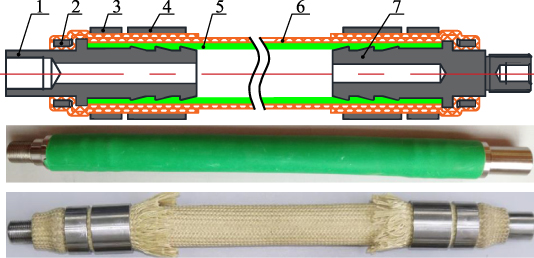
Figure 2. The structure of WHAM developed by the author of this paper [13] Reproduced from 2017. (1) Hollow end fitting. (2–4) Crimping ring. (5) Rubber tube. (6) Fibre sleeve. (7) Closed end fitting. © IOP Publishing Ltd. All rights reserved.
Download figure:
Standard image High-resolution imageTo sum up, the failures of WHAM include fibre fracture, rubber tube coming out from fibre sleeve, rubber tube breaking, end fitting slipping out and fibre sleeve loosening. The main objective of this research is to improve the strength of WHAM. Firstly, the effects on WHAM strength were analysed theoretically and the structure of WHAM was improved. Secondly, the factors effecting the strength of WHAM were analysed by the orthogonal experiment. Finally, the fibre strands' stress state, the ratio of fibre sleeve coverage area to rubber tube outer wall area, the contributions of rubber tube wall thickness and end fitting structure for WHAM's strength were analysed. The improved WHAM strength depends on the initial braid angle, fibre material, rubber tube wall thickness, and the rubber tube's deformation.
2. Theoretical analysis of WHAM strength
The relationship about muscle driving force with initial braiding angle, pressure, and the rubber tube's diameter is described in the static models of WHAM. The most widely used model is [36]:

where p is operating pressure, D0 is the diameter of the WHAM,  is contraction ratio, a, b is a constant related to the initial braid angle. WHAM strength can be evaluated from two dimensions. One is the maximum driving force of the muscle, and the other is the maximum operating pressure. The fibre strands will be more likely to fracture with the great driving force F, and the rubber tube will be more likely to burst under the great pressure p. In addition, the effects of rubber tube wall thickness and the irregular deformation of end fitting structure are ignored in this model. However, the tube wall thickness and end fitting structure have crucial effects on WHAM strength. Therefore, the effects of the tube wall thickness, end fitting structure, initial braid angle, and fibre material on the WHAM strength need to be researched.
2.1. Fibre stress state and fibre sleeve coverage area
Compared with the rubber tube, the fibre strand has a higher modulus. In the expansion and contraction, fibre sleeve limits the rubber tube's expansive deformation, resulting the tension is formed in fibre strands. Therefore, the WHAM strength mainly depends on the fibre strands' strength rather than the rubber tube. In the ideal case, force is distributed in each fibre strand evenly. Referring to the force balance theory, it can be obtained that the tensile force f acted on a single fibre strand is [41]:
where L is the WHAM length, N is the number of fibre sleeve spindles that is equal to the number of fibre bundles, n is the number of strands for each bundle, θ0 is the initial braid angle, B is the initial length of fibre, respectively. Equation (2) indicates the tensile force acted on a single fibre strand, which is related to the operating pressure, initial braid angle and the number of fibre strands. The relationship between the force acted on a single fibre strand and initial braid angle is shown in figure 3, when the WHAM's initial braid angle, the diameter, N, and n are 25°, 30 mm, 96, and 3, respectively. The force acted on fibre strand and the operating pressure are positively correlated, when the initial braid angle is constant. Meanwhile, the force acted on fibre strands will decrease if the initial braid angle increases.
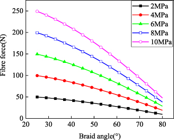
Figure 3. Relationship between the tensile force acted on fibre strand and initial braid angle.
Download figure:
Standard image High-resolution imageThe fibre sleeve's load capacity relies on the fibre strand's strength and the number of fibre strands. It should be ensured that the fibre strands' stress is lower than its allowable stress, which needs the fibre sleeve to be made of high strength fibre material. UHMWPE is the fibre with a high strength. Moreover, its density is 0.97 g cm−3 and modulus is 88 ∼ 135 GPa. In addition, the density of aramid 1414 is 1.44 g cm−3 and the modulus of aramid is 63 ∼ 127 GPa, which also meets the requirements of WHAM's strength. Therefore, these two kinds of fibre are used to weave fibre sleeve, in this study. Besides the fibre materials, the number of fibre strands will also affect the strength of WHAM. The force acted on a single fibre strand is reduced with the increasing of the number of fibre strands. Therefore, WHAM strength can be improved by increasing the number of fibre strands.
Fibre sleeve is used as a reinforcing structure and withstand most of the load, when the WHAM contracts. Moreover, the fibre sleeve limits rubber tube's deformation, which avoids the rubber tube coming out from the fibre sleeve. Increasing the number of fibre strands can not only improve the stress state of each fibre strands, but also increase the ratio of fibre sleeve coverage area. The fibre sleeve is composed of multiple fibre strands woven along the helix. Meshes in the fibre sleeve will occur even in the initial state, as shown in figure 4, if there are few fibre strands.
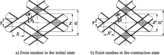
Figure 4. Structure of the fibre sleeve with meshes.
Download figure:
Standard image High-resolution imageThe structure of meshes in the initial state of fibre sleeve is shown in figure 4(a), and the diagonal length of diamond mesh Z is:
where the circumferential node along the WHAM is N/2, and the axial node is 2L0/(X+ Zcotθ0) + 1, so the total nodes in the fibre sleeve is Nt = N/2 × [2L0/(X+ Zcotθ0) + 1], and the initial area of each node is Ssingle node = W/2cosθ0sinθ0, where Ws = Sd is the width of fibre bundles composed of S parallel fibre strands, and d is the diameter of a single fibre strand. Thus, the area of all nodes in the fibre sleeve Stotal node is:
In the initial state, the whole fibre strands' initial interface with the rubber tube is Scontact = NSBd−Snode. And the maximum contact area is πD0 L0. The relationship between coverage ratio η0 and the initial braid angle is:
Total nodes of the WHAM are N't = Nt, when the WHAM contracts. Each node area is S'single node = Ws 2/2cosθsinθ. The area of all the nodes in the fibre sleeve is S'total node = N't × S'single node. The entire fibre sleeve contact area with rubber tube is S'contact = NnBd−S'total node. The relationship between coverage ratio η and the initial angle is:
The fibre sleeve completely covers the outer surface of rubber tube, when the number of fibre bundles is sufficient. Consequently, there is no mesh in the fibre sleeve composed of multiple strands. During the contraction, muscle's shape is changing, and mesh is emergent, as shown in figure 5. The horizontal axis is the length direction of the artificial muscle. The contact surface at any braid angle can be obtained in the initial and the contracted state. Initially, no mesh appears in fibre sleeve, Z= 0. Axial nodes are 2L0/X+ 1, the nodes of artificial muscle in the circumferential direction are N/2. In the contraction, the situation that Z is not equal to 0 may occur, so the total nodes are:
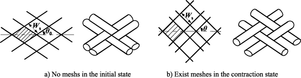
Figure 5. Structure of the fibre sleeve with the initial coverage area ratio η0 = 1.
Download figure:
Standard image High-resolution image
when Z< 0, fibre strands are overlapping; when Z= 0, the fibre sleeve just completely covers the outer surface of rubber tube, and when Z> 0, the fibre sleeve has meshes. The area of each node is S'single node = Ws 2/2cosθ0sinθ0, so the area of total nodes on the fibre sleeve S'total node can be calculated as:
The relationship between the ratio of fibre sleeve coverage area η and the initial braid angle is:
From equation (9), the relationship between the coverage area ratio and the contraction rate can be obtained, as shown in figure 6. In the contraction, the coverage area ratio firstly decreases and then increases with the increase of contraction rate. The high coverage area ratio can be obtained with a large initial braid angle. The possibility of rubber tube coming out from the fibre sleeve is decreased with the increasing of coverage area ratio.
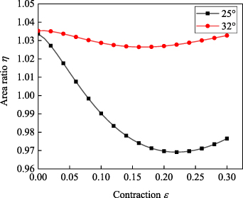
Figure 6. Relationship between fibre sleeve coverage area ratio and contraction ratio.
Download figure:
Standard image High-resolution imageIn summary, the initial braid angle, the fibre material, and the number of fibre strands have vital effects on WHAM strength. Choosing a reasonable initial braid angle and the number of fibre strands will not only decreases the force acted on fibre, but also increases the fibre sleeve coverage area to reduce the possibility of rubber tube coming out.
2.2. Effect of rubber tube wall thickness on WHAM strength
Although the strength of the WHAM mainly depends on the fibre sleeve, the rubber tube will first fail before the fibre fractures if the strength of rubber tube is not enough, reducing the load capacity of the WHAM. Kothera [41] has established a variable wall thickness model, which takes into account the change of the rubber tube wall thickness with the contraction ratio of WHAM. The WHAM drive model considering the variable of wall thickness is:
where,
where t0 is the initial wall thickness of the rubber tube. This model uses the virtual work principle, that is, the external work by the WHAM is equal to the work by the fluid on WHAM. The volume of WHAM and wall thickness of the rubber tube are changed, when the fluid is added into the WHAM. This model has an assumption that the fibre length remains constant during the artificial muscle contraction. However, fibres will inevitably be deformed when the WHAM contracts. The fibre as a reinforcing structure maintains the deformation of the rubber tube. The deformation of the rubber tube will be small, when the fibre has great tensile stiffness. The force acted on the rubber tube in the middle is generated by the extrusion of the fluid and the fibre sleeve. When WHAM contracts, the rubber tube wall thickness becomes thinner than the initial state. The rubber tube is coming out from the fibre sleeve at a certain critical wall thickness. Relatively, the force acted on the rubber tube at the end is more complicated than the middle. Besides the action of fluid and fibre, there is also the shear force from the crimping ring on the rubber tube. When the rubber rube is deformed, the end of rubber tube contact with crimping rings will also receive the shearing force from the crimping ring. The ability of the rubber tube to resist shear deformation depends on the fibre tensile stiffness and the rubber tube wall thickness. If fibre has great tensile stiffness, the rubber tube's radial expansion will be small, which means the small shearing force on the end of rubber tube.
A suitable wall thickness can be determined by analysing the effect of the rubber tube wall thickness on the WHAM's strength. Firstly, the rubber tube wall thickness should be thin, as much as possible, to avoid excessive energy consumption. Secondly, a rubber tube should be ensured work normally before the fibre fails within a reasonable wall thickness range. If a rubber tube has too thin wall thickness, it will be coming out from the fibre sleeve. To avoid this failure, Mori [25] uses a rubber tube with a 5 mm wall thickness to make artificial muscle. However, the rubber tube wall thickness is one factor that causes the nonlinear characteristics of WHAM. Actually, the rubber tube is a high-molecular polymer, and its tensile properties have strong nonlinear characteristics. Moreover, the irregular deformation of the WHAM at the end becomes obvious with the increasing of rubber tube wall thickness. In an ideal state, the rubber tube wall thickness is sufficiently thin, and the nonlinear effect of the rubber tube can be ignored. The hydraulic artificial muscle's shape is always a cylinder, that is, there is no irregular deformation at the end. Physical factor models proposed by Chou [14] and Tondu [15] testify that the rubber tube wall thickness has a great nonlinear effect on the WHAM driving characteristics, especially, at initial length. The effect of the wall thickness decreases with the growth of contraction rate. On the other hand, the effect of wall thickness will increase with the increasing of pressure. The nonlinear effect of the 5 mm wall thickness on WHAM's driving characteristic is 29.3%, for a WHAM with the initial braid angle of 25°, the initial length of 300 mm, and the operating pressure of 5 MPa. The nonlinear effect can be reduced to 11.7% and 17.6% for 2 and 3 mm tube wall thickness, respectively. Another effect of the rubber tube wall thickness on WHAM is its maximum contraction rate. Mori [25] has developed a WHAM that maximum contraction rate is 24% with a 5 mm wall thickness. The maximum contraction rate of WHAM with 2 and 3 mm wall thickness is 36% and 28%, respectively. For the WHAM manufactured by thin wall thickness rubber tube must be used close fibre spacing to improve the stress state of rubber tube and ensure high-intensity output and large-range contraction for WHAM.
2.3. WHAM end fitting structure design and optimization
The end fittings connect the rubber tube and fibre sleeve. Meanwhile, the end fittings play the role of sealing. The material of end fitting is 316 l stainless steel. The barbs were designed on the end fittings, with a height of 1 ∼ 2 mm and the number of 3 ∼ 4 [26]. Using X90 automatic pipe press machine, the swaged crimping rings were pressed to the fibre sleeve. Continually, the rubber tube was pressed onto the trench and the barbs of the end fittings. The above method is to fix the end fitting, rubber tube, and fibre sleeve, and that is non-removable. The rubber tube's deformation is an important parameter that affects the sealing performance and resistance pulling out strength of WHAM. Therefore, the reliability of WHAM can be improved through an advanced end clamping process. The WHAM end fitting structure of pressing and no-pressing is shown in figure 7. After pressing, the outer diameter of the swaged crimping rings is:


Figure 7. End fitting structure of pressing and no-pressing.
Download figure:
Standard image High-resolution imagewhere Dr, Dr0, σ, and Δx are outer diameter of swaged crimping ring after pressing, outer diameter of swaged crimping ring before pressing, the sum of the clearance which include the clearance between crimping ring and the fibre sleeve, and the clearance between end fitting and rubber tube, and the deformation of the rubber tube, respectively.
The unreasonable structure design of end fitting and deformation of the rubber tube will lead to WHAM failure at the end. The failure modes of the WHAM at the end are as follows: firstly, if the deformation of the rubber tube or the load is too large, the rubber tube is willing to burst or pull out. Secondly, supposing the deformation of the rubber tube is too small, the rubber tube and end fitting will leakage. Thirdly, if the number of barbs, depth, and groove spacing design is not reasonable, it will lead to the rubber tube shear deformation too large, resulting in the end of rubber tube breakage. Preliminary experiment results show that some failure modes can be avoided by improving the processing technology, such as fibre sleeve loosening, crimping rings slippage, and rubber tube slipping out, as shown in the figure 8.
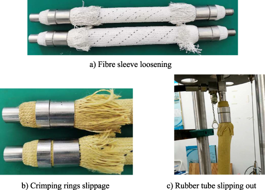
Figure 8. Failure modes for preliminary experiment.
Download figure:
Standard image High-resolution imageThe improved design of the end fitting structure including the number of barbs and swaged crimping rings can effectively avoid some failure modes of WHAM, such as the swaged crimping rings sliding and the leakage at the end. The significant effect factors of end fitting structure are the deformation of the rubber tube, the number of barbs and crimping rings. Therefore, eight types of WHAM were compared to explore the reasonable structure. The common among these include that UHMWPE is selected as fibre sleeve material, rubber tube outer diameter is 30 mm, wall thickness is 2 mm, initial length is 300 mm, the initial angle is 25° and the thickness of the crimping ring is 3 mm. The difference between them lies in the deformation of the rubber tube, the number of barbs and crimping rings, as shown in figures 9(a)–(c). The deformations of the rubber tube are 1.25 and 1.5 mm. Silicone adhesive was used to prevent crimping ring from sliding off. The WHAM with four barbs was broken at the end under the 4 MPa pressure, while the WHAM with three barbs was not broken under the 4 MPa pressure, as shown in figure 9(d). The barbs on the end fitting can enhance the friction between rubber tube and end fittings, which prevents the rubber tube from pulling out. The rubber tube pulls out easily when the number of barbs is one or two. Moreover, the anti-pulling force is enhanced, obviously, when the number of barbs is three or four. However, the more the barbs are on the end fittings, the more serious stress concentration are on the rubber tube. The rubber tube would be pressed by the swaged crimping rings when WHAM is manufactured, and the deformation of the rubber rube would be aggravated with the increase of barbs. Thus, compared with three barbs, the WHAM with four barbs is more probable to break at the end. In addition, compared with one crimping ring, the two crimping rings of WHAM are prone to slip. This is because the crimping ring interacts with the shoulder of the end fitting after pressing, which can resist the thrust on the crimping ring from the rubber tube when WHAM contracts. The WHAM failure mode was rubber tube slipping out when the deformation of rubber tube is 1.25 mm. Therefore, in the following test, the number of barbs and crimping ring were designed to be 3 and 1, respectively. And deformation of the rubber tube should greater than 1.25 mm.
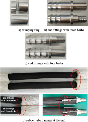
Figure 9. End fitting structure and rubber tube broken.
Download figure:
Standard image High-resolution image3. Experiments
According to the previous tests, the failure modes of WHAM were explored, and the main factors affecting its strength were determined, which contains initial braid angle, fibre material, rubber tube wall thickness and the deformation of the rubber tube. By analysing the fibre sleeve coverage area ratio, it was determined that the number of fibres bundles was 96, and each bundle contained three fibre strands. The orthogonal experiment was designed to investigate each factor's significance level on the WHAM's strength.
3.1. Orthogonal experiment about factors affecting WHAM strength
After analysis of fibre sleeve stress state and improvement of the end fitting structure, the main factors affecting the WHAM strength were finally determined, including initial braid angle, rubber tube wall thickness, fibre material and the deformation of the rubber tube. Two levels were taken for each factor, and the factors and levels were obtained, as shown in table 1.
Table 1. Test factors and levels [40] 2010, reprinted by permission of the publisher (Taylor & Francis Ltd, www.tandfonline.com.).
| Levels Factors | ||||
|---|---|---|---|---|
| A (Initial braid angle/°) | B (Fibre) | C (Thickness of tube/mm) | D (Δx/mm) | |
| 1 | 25 | UHMWPE | 2 | 1.5 |
| 2 | 32 | Aramid 1414 | 3 | 1.7 |
The orthogonal experiment with four factors and two levels were designed, as well as considered the interaction among factors, including six interactions A × B, A × C, A × D, B × C, B × D and C × D. The sum of degrees of freedom is 10. Although orthogonal table L8(27) has seven degrees of freedom, it is not suitable for this multi-factor experiments, so the larger orthogonal table L16(215) was used. The tests design of WHAM strength is shown in table 2.
Table 2. Design of orthogonal scheme for WHAM strength Reproduced from 2017. © IOP Publishing Ltd. All rights reserved.
| A | B | C | D | |
|---|---|---|---|---|
| Actuators | Initial braid angle/° | Fibre | Thickness of tube/mm | Δx/mm |
| 1 | 25 | UHMWPE | 2 | 1.5 |
| 2 | 25 | UHMWPE | 2 | 1.75 |
| 3 | 25 | UHMWPE | 3 | 1.5 |
| 4 | 25 | UHMWPE | 3 | 1.75 |
| 5 | 25 | Aramid 1414 | 2 | 1.5 |
| 6 | 25 | Aramid 1414 | 2 | 1.75 |
| 7 | 25 | Aramid 1414 | 3 | 1.5 |
| 8 | 25 | Aramid 1414 | 3 | 1.75 |
| 9 | 32 | UHMWPE | 2 | 1.5 |
| 10 | 32 | UHMWPE | 2 | 1.75 |
| 11 | 32 | UHMWPE | 3 | 1.5 |
| 12 | 32 | UHMWPE | 3 | 1.75 |
| 13 | 32 | Aramid 1414 | 2 | 1.5 |
| 14 | 32 | Aramid 1414 | 2 | 1.75 |
| 15 | 32 | Aramid 1414 | 3 | 1.5 |
| 16 | 32 | Aramid 1414 | 3 | 1.75 |
3.2. Test samples and equipment
Sixteen WHAM samples were manufactured, as shown in figure 10. These initial lengths are 300 mm and external diameters are 30 mm. According to equation (9), the fibre sleeve coverage area ratio is close to 1, when the fibre width after weaving is 0.6 mm. UHMWPE and aramid 1414 with deniers of 1600 D and 1500 D were selected, respectively. Fibre diameter can be calculated according to the equation (13). The fibre denier Da represents the weight of fibre with length of 9000 m. The diameters of the UHMWPE and aramid were 0.48 and 0.38 mm at the natural state, respectively. After making WHAM, the shape of fibre changes from a cylindrical to a flat. The actual measurement UHMWPE width is 0.64 mm, and the aramid width is 0.6 mm:

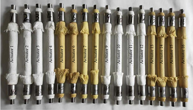
Figure 10. Test samples of WHAM.
Download figure:
Standard image High-resolution imageThe test system includes a power pack, control unit and installation platform, as shown in figure 11. Its power pack is a water hydraulic comprehensive performance testing bed manufactured by HYTAR of Finland. The pressure control unit is a hydraulic circuit composed of a water-hydraulic proportional throttle valve and a manual one-way throttle valve to regulate the operating pressure of WHAM. The pressure gauge and sensor are connected to the transition block of the water-hydraulic proportional throttle valve to measure the output pressure of the hydraulic circuit. The upper end of the installation platform is the flower basket bolt, which is used to install and fix the WHAM. The lower end is connected with a tension sensor and joint bearing to prevent the axis from eccentricity. The sensor parameters used in the tests are shown in table 3.
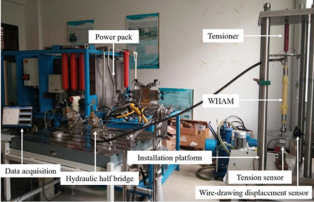
Figure 11. Experiment device.
Download figure:
Standard image High-resolution imageTable 3. Sensor parameters.
| Sensor | Measuring range | Accuracy | Output voltage |
|---|---|---|---|
| Pressure sensor | 0–10 MPa | 0.1% FS | 0–10 V |
| Tension sensor | 0–30 kN | 0.3% FS | 0–10 V |
4. Results
Damage tests were carried out on 16 WHAMs. Since the WHAM produces the maximum driving force when they are in the initial length, the initial long state muscles were tested on the test bench, as shown in figure 11. High pressure water was inputted into the rubber tube, and the WHAM generated driving force. If the water pressure continuously increases, at a certain critical point, the muscle will be destroyed. The maximum driving force Fmax and maximum operating pressure pmax were collected, as shown in table 4. The comparison of driving forces is shown in figure 12. All driving forces of Muscles were greater than 20 kN and the maximum driving force was 36.2 kN. The comparison of pressures is shown in figure 13. All operating pressure were greater than 5 MPa and the highest operating pressure was 17.9 MPa.

Figure 12. Driving forces of 16 samples.
Download figure:
Standard image High-resolution image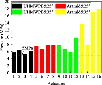
Figure 13. Comparison of 16 samples pressure.
Download figure:
Standard image High-resolution imageTable 4. Test results of 16 WHAMs destruction.
| Actuators | 1 | 2 | 3 | 4 | 5 | 6 | 7 | 8 | 9 | 10 | 11 | 12 | 13 | 14 | 15 | 16 |
|---|---|---|---|---|---|---|---|---|---|---|---|---|---|---|---|---|
| Fmax (×104 N) | 3.16 | 3.59 | 2.64 | 3.08 | 3.62 | 3.46 | 3.13 | 3.27 | 2.08 | 2.60 | 2.01 | 2.96 | 3.25 | 2.13 | 3.21 | 3.29 |
| Pmax (MPa) | 5.77 | 6.34 | 5.32 | 6.12 | 7.60 | 6.68 | 7.81 | 7.83 | 7.77 | 6.80 | 5.90 | 9.90 | 13.8 | 7.90 | 17.0 | 17.9 |
4.1. Orthogonal experiment analysis
The driving force and operating pressure of WHAM were used as test indexes to variance analysis for orthogonal experiment results. By using the F test method, the critical value of variance analysis is F0.01(1,5) = 16.26, F0.05(1,5) = 6.61, F0.1(1,5) = 4.06, and F0.2(1,5) = 2.2. The analysis results are shown in table 5. The test results show that initial braid angle A and fibre material B have the greatest effects on muscle strength.
Table 5. Variance analysis of 16 WHAMs destruction.
| F | A Braid angle | B Fibre | A × B | C Thickness | A × C | B × C | D Δx | A × D | B × D | C × D |
|---|---|---|---|---|---|---|---|---|---|---|
| Fmax | 16.21 | 8.82 | 1.22 | 0.08 | 8.02 | 1.15 | 1.34 | 0.14 | 9.54 | 3.13 |
| pmax | 22.23 | 21.07 | 7.80 | 4.53 | 3.74 | 3.88 | 0.05 | 0.12 | 2.10 | 3.31 |
Significance analysis was carried out by taking Fmax as the index. The braid angle A, fibre material B, and interaction of A × C, B × D and C × D had an impact on the WHAM strength. On the contrary, A × B, wall thickness C, B × C, deformation of the rubber tube D, A × D had a few effects. According to the binary diagram, the optimal level can be determined as A1B2C1D1, as shown in figure 14. The test results show that the axial strength of the WHAM was the best, when the initial braid angle is 25°, the fibre material is aramid fibre, the wall thickness is 2 mm, and the deformation of the rubber tube is 1.5 mm.
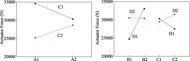
Figure 14. Interaction diagram of driving forces of 16 WHAMs destruction.
Download figure:
Standard image High-resolution imageSignificance analysis was carried out by taking pmax as the index. The factors of braid angle A, fibre material B, and interaction of A × B, A × C, B × C, and C × D had an impact on the WHAM strength. On the contrary, the deformation of the rubber tube D, A × D and B × D had a few effects. According to the binary diagram, the optimal level can be determined as A2B2C2D2, as shown in figure 15. The test results show that the withstand pressure capacity of the WHAM was the best, when the initial braid angle is 32°, the fibre material is aramid 1414, the wall thickness is 3 mm, and the deformation of the rubber tube is 1.7 mm.
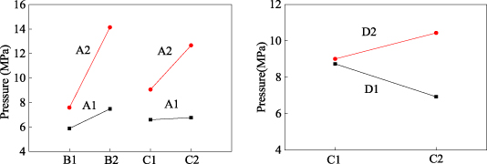
Figure 15. Interaction diagram of working pressure scheme of 16 WHAMs destruction.
Download figure:
Standard image High-resolution image4.2. Analysis of WHAM failure
The test results show that the improved end fitting structure can effectively avoid the crimping ring slippage and rubber tube slipping out. Rubber tube coming out from the fibre sleeve is effectively solved by promoting the coverage area ratio of fibre sleeve. The improved design makes the WHAM failure stably present two forms. One is only the rubber tube breakage at the end, but the fibre sleeve is intact. The other is the rubber tube and fibre sleeve broken in the middle of the WHAM, as shown in figure 16.
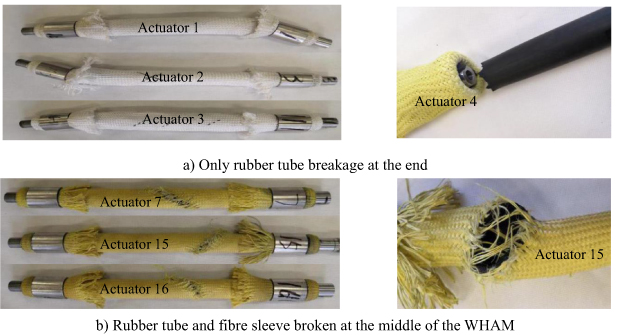
Figure 16. Failure of 16 WHAMs destruction.
Download figure:
Standard image High-resolution image5. Discussion
From the orthogonal experiment, it could be found that the failure modes of WHAMs were different with different structure parameters. Firstly, all WHAMs manufactured by UHMWPE (No. 1–4 and No. 9–12) failed in the form of rubber tube breakage. Furthermore, some WHAMs manufactured by aramid 1414 (No. 7, 15 and 16) failed in the rubber tube and fibre fracture in the middle. Secondly, the rubber tube did not come out from the fibre sleeve in the 16 samples, when the ratio of fibre sleeve coverage area to rubber tube outer wall area is more than 0.97. Finally, the failure modes of all WHAMs with 2 mm wall thickness were tube breakage at the end, and the failure modes of some WHAMs with 3 mm thickness were fibre fractures. In section 5.1, the force act on the different materials fibre strands were calculated and compared. In section 5.2, the effect of the fibre sleeve coverage area ratios on the WHAM's strength were analysed. In section 5.3, the ratio between rubber tube's deformation and wall thickness was calculated and the effect of rubber tube's deformation on the WHAM's strength were analysed.
5.1. Stress state of fibre strands
The test results show that the breaking load of the WHAM with aramid was greater than UHMWPE. Kothera [41] considered the effect of elastic energy storage on the driving characteristics of fluid artificial muscle. From equation (1), the theoretical model of WHAM's driving characteristics can be modified as:

where U is the elastic potential energy of a fibre strand. Therefore, considering the fibre elongation and deformation, the driving force of fluid artificial muscle is expressed as:
where Abraid and E are the cross-sectional area and the elastic modulus of the fibre, respectively. Equation (15) indicates that the tensile stiffness Abraid E of fibres results in the differences of driving characteristics of WHAMs with different fibre materials. The mechanical properties of the UHMWPE and aramid were tested by the CTM8010 microcomputer control electronic universal material testing machine, and the results are shown in figure 17. The UHMWPE breaking load, breaking elongation and elastic modulus were 279.12 N, 4.5% and 32.29 GPa, respectively. The aramid fibre breaking load, breaking elongation and elastic modulus were 307.84 N, 3.3% and 86.36 GPa, respectively. The maximum load of the test machine is 10 kN and the load accuracy is ±0.01%. The measurement accuracy of the load is within ±0.3% of the indicated value, and the measurement accuracy of the displacement is within ±0.1% of the indicated value.
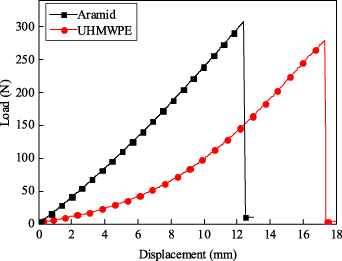
Figure 17. Fibre tensile tests for UHMWPE and aramid.
Download figure:
Standard image High-resolution imageThe fibre tensile test results show that the tensile stiffness of the aramid was greater than the UHMWPE, as shown in figure 18. Therefore, combining with equation (15), the theoretical driving force of the WHAM woven by aramid is greater than the WHAM woven by UHMWPE. The 16 WHAM samples were divided into eight pairs to compare the strength of WHAM, and each pair used two different fibres. The eight pairs of samples are actuator 1 compared with actuator 5, actuator 2 compared with actuator 6, actuator 3 compared with actuator 7, actuator 4 compared with actuator 8, actuator 9 compared with actuator 13, actuator 10 compared with actuator 14, actuator 11 compared with actuator 15, and actuator 12 compared with actuator 16. The comparison tests results are shown in figure 12. The results show that the driving force of the WHAM woven by aramid is greater than the WHAM woven by UHMWPE. Thus, the force acted on aramid is greater than UHMWPE. Assume that the fibre bundles are evenly stressed when the WHAM is driven. According to the force balance principle, the forces acted on fibre strands of the 16 samples can be obtained, as shown in table 6, and the comparison of forces acted on fibre strands is shown in figure 19. Similar to the strength comparison, the forces acted on fibre strands of eight sets samples were compared. The results proved that the force acted on aramid is greater than UHMWPE. For example, actuator 12 and actuator 16 differs only in fibre material. When actuator 12 was broken, the force acted on UHMWPE strands was about 155.13 N. When actuator 16 was broken, the force acted on aramid strands was about 193.09 N. Therefore, the failure mode of actuator 12 was the end of rubber tube breaking and the failure mode of actuator 16 was fibre fracture.
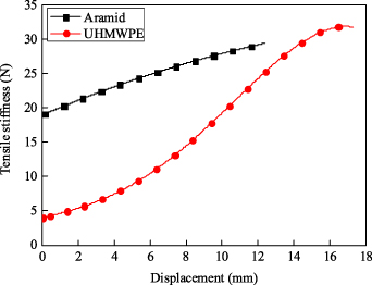
Figure 18. Tensile stiffness of UHMWPE and aramid.
Download figure:
Standard image High-resolution image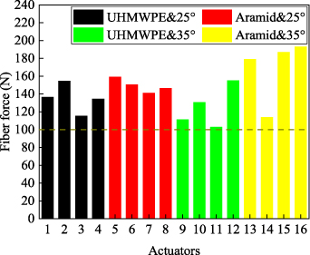
Figure 19. Comparison of forces acted on fibre strands when WHAMs were broken.
Download figure:
Standard image High-resolution imageTable 6. Tensile force of fibre strand and driving forces of 16 groups WHAMs.
| Actuators | 1 | 2 | 3 | 4 | 5 | 6 | 7 | 8 | 9 | 10 | 11 | 12 | 13 | 14 | 15 | 16 |
|---|---|---|---|---|---|---|---|---|---|---|---|---|---|---|---|---|
| Fmax (×104 N) | 3.16 | 3.59 | 2.64 | 3.08 | 3.62 | 3.46 | 3.13 | 3.27 | 2.08 | 2.60 | 2.01 | 2.96 | 3.25 | 2.13 | 3.21 | 3.29 |
| f (N) | 136.69 | 154.71 | 115.55 | 134.57 | 159.27 | 150.65 | 141.07 | 146.48 | 111.45 | 130.58 | 102.88 | 155.13 | 179.11 | 113.96 | 187.00 | 193.09 |
The different stress states of fibre strands lead to different failure modes of WHAMs. All WHAMs manufactured by UHMWPE were broken at the end, while some WHAMs manufactured by aramid were broken in the middle, such as, actuator 7, actuator 15 and actuator 16. The comparison of forces acted on fibre when WHAMs were broken is shown in figure 19. The force acted on the fibre strand of actuator 12 was the largest among actuators with UHMWPE, and the value was 155.13 N. The force acted on the fibre strand of actuator 16 was the largest among actuators with aramid, and the value was 193.09 N. According to the fibre tensile tests, the forces acted on the fibre strands of actuators were less than their breaking load, as shown in figure 17. In fact, due to the effects of nonlinear factors such as the friction, the load is not evenly withstood by each fibre strand, which causes the forces acted on some fibre strands lager than others. Under the action of nonlinear factors, some fibre strands of actuator were first broken. In addition, the forces acted on fibre strands of actuator 7 was only 141.07 N that is far less than breaking load, but the fibre strands were still broken. This phenomenon was caused by the uneven load generated on some fibre strands during the production process of WHAM. Moreover, the fibre fracture has common features, which the direction of fracture is along the fibre spiral path and the position of fracture is in the middle instead of end. Therefore, under the effects of nonlinear factors, one fibre strand in the fibre sleeve is first broken. An impact load is produced by the released energy when the first fibre was broken, which causes breakage on the fibre strands contacted with the breaking one. Without fibre sleeve's enhancement, the rubber tube was crushed by the high-pressure fluid along the fibre spiral path.
5.2. Ratio of fibre sleeve coverage area
In order to prevent the rubber tube from coming out of the fibre sleeve, fibre sleeves of WHAMs are made with 96 close placed fibre bundles, each consisting of three fibre strands. From equation (9), the same coverage area ratio of actuator 5, 6, 7, 8 is the smallest among the 16 samples. The fibre sleeve of WHAM developed by Mori [40] consists of 48 fibre bundles, each consisting of three fibre strands. The single fibre strand diameter and initial braid angle are 0.8 mm and 35°, respectively. From equation (3), it could be calculated that the ratio of fibre sleeve coverage area to rubber tube outer wall area is 0.82 of Mori's WHAM at the initial state. The trend of coverage area ratios with the contraction of WHAM is shown in figure 20. That the rubber tube came out from the fibre sleeve was observed in Mori's experiments [40], as shown in figure 21. The minimum coverage rate ratio of Mori's WHAM is 0.79. Combined with the theoretical analysis on fibre sleeve coverage area, the ratio can be increased to prevent the rubber tube from coming out. Therefore, the sample (actuator 5, 6, 7, and 8) is manufactured and tested. The minimum coverage rate ratio of actuator 6 is 0.97, and the rubber tube did not come out from the fibre sleeve. Moreover, the actuator 6 was broken under the pressure of 6.68 MPa more than 1.8 MPa referring to [40]. Therefore, increasing the coverage area ratio of actuator can effectively avoid the rubber tube coming out from the fibre sleeve.
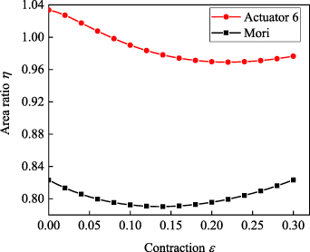
Figure 20. Coverage area ratios of Mori's WHAM and actuator 6.
Download figure:
Standard image High-resolution image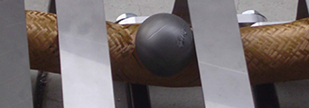
Figure 21. Rubber tube expanded too much and coming out from the sleeve (1.8 MPa) [40] 2010, reprinted by permission of the publisher (Taylor & Francis Ltd, www.tandfonline.com.).
Download figure:
Standard image High-resolution image5.3. Tube wall thickness and deformation of the rubber tube
Among the 16 samples, all the muscles with 2 mm wall thickness were broken at the end of rubber tube, and the broken positions were all at the first barb of the end fittings. This is because the stress concentration of rubber tube is great at the position of the first barb. A parameter K= Δx/t (0 ⩽ K⩽ 1) is introduced to indicate the degree of the rubber tube stress concentration, where t is the thickness of the rubber tube. The degree of stress concentration is increasing with the growth of K. Moreover, K also represents the tightness of the connection among the rubber tube, fibre sleeve and end fittings. The rubber tube and fibre sleeve will be likely to slip out with a small K. When deformation of rubber tube Δx equals 1.5 mm, the K is 0.75 for the WHAMs with 2 mm rubber tube wall thickness, and the K is 0.5 for the WHAMs with 3 mm rubber tube wall thickness. When deformation of rubber tube Δx equals 1.75 mm, the K is 0.875 for the WHAM with 2 mm rubber tube wall thickness, and the K is 0.58 for the WHAM with 3 mm rubber tube wall thickness. The relationships between the parameter K and the strength of the WHAMs with the different fibre materials and the initial braid angles are shown in figure 22. The K of actuators 7, 15 and 16 have less reference significance when the effect of rubber tube wall thickness on WHAM strength is explored, because the failure mode of these three actuators is fibre fracture. The WHAM strength decreased with the increase of K, for the aspect of stress concentration. And the test results show that WHAMs with aramid show this corresponding trend after removing the reference points of actuators 7, 15 and 16, as shown in figures 22(c) and (d). Additionally, the fibre sleeve produces tiny slippage that will not damage the WHAM, but these slippages cause the braid angle increasing, for the aspect of tightness of the connection. According to equation (1), the driving force of WHAM decreases as the braid angle increases. Related studies shown that the friction coefficient of UHMWPE is less than aramid [42, 43]. As a result, the UHMWPE is more prone to slippage. Therefore, the driving force of WHAM woven by UHMWPE increases with the increase of K. Besides, the trend of WHAM's driving force with K should be consistent with the trend of pressure with K, for the given fibre material, initial braid angle and rubber tube wall thickness, as shown in figures 22(a) and (d). However, some test results show that the trends were inconsistent, as shown in figures 22(b) and (c), which is caused by the change of braid angle due to the slippage of fibre sleeve. Actually, the effect factors of WHAM's strength and failure modes is various and complicated. And, the coupling effect of these factors on WHAM should be researched in future work.
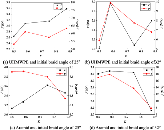
Figure 22. Relationships between K and strength of WHAM with different fibre materials and initial braid angles.
Download figure:
Standard image High-resolution imageThe fibre sleeve loosening was observed in Mori's experiments [40], as shown in figure 23. Based on the structure of Mori's muscle, a non-detachable fix method of end fitting structure was developed to avoid the fibre sleeve loosening. The ends of the 16 samples were fixed by a non-detachable method. As a result, the end fittings were not slipping out and the fibre sleeve was not loosening.

Figure 23. Fibre sleeve loosening [40] 2010, reprinted by permission of the publisher (Taylor & Francis Ltd, www.tandfonline.com.).
Download figure:
Standard image High-resolution image
6. Conclusions
- (a)The factors, from strong to weak, that affect the driving force of the WHAM, are the initial braid angle, the fibre material, the deformation of the rubber tube, and the rubber tube wall thickness. The factors, from strong to weak, that affect the ability of WHAM to withstand fluid pressure, are the initial braid angle, the fibre material, the rubber tube wall thickness, and the deformation of the rubber tube. Affected by multiple factors, the effect of a single factor is amplified or weakened. The double effects about the fibre material and the deformation of the rubber tube have the strongest influence on the driving force of WHAM. The double effects about the initial braid angle and the fibre material have the strongest influence on the ability to withstand fluid pressure.
- (b)The breaking force of the WHAM was 36.2 kN, when the initial braid angle is 25°, the fibre material is aramid, the rubber tube wall thickness is 2 mm, and the deformation of rubber tube is 1.5 mm. The maximum water filling pressure of the WHAM was 17.9 MPa, when the initial braid angle is 32°, the fibre material is aramid, the rubber tube wall thickness is 3 mm, and the deformation of rubber tube is 1.75 mm. If WHAM with higher axial load capacity is needed, a smaller initial braid angle should be chosen. If WHAM with a good ability to withstand fluid pressure is needed, a large initial braid angle and thick rubber tube wall thickness should be chosen.
- (c)Theoretical analysis shows that increasing the fibre sleeve coverage area can avoid the rubber tube coming out from the fibre sleeve. And, the ratio of fibre sleeve coverage area to rubber tube outer wall area is 0.97, when fibre sleeve consists of 96 close placed fibre bundles and each consisting of three fibre strands. The failure mode of the rubber tube coming out from the fibre sleeve was avoided. In addition, the failure modes of end fitting slipping out and fibre sleeve loosening were avoided by improving the end fitting structure. Finally, the improved structure failure modes were the rubber tube breaking at the end or the fibre fracture in the middle.
- (d)The force acted on fibre strands is related about initial braid angle and the fibre material and it would be increasing with the decreasing of initial braid angle or the increasing of tensile stiffness. The tensile stiffness of aramid is greater than UHMWPE. Therefore, under the same conditions, the driving force of the WHAM woven by aramid is greater than the WHAM woven by UHMWPE. Meanwhile, the force acted on a single aramid strand is greater than UHMWPE, and the WHAM woven by aramid are more prone to cause fibre fracture than the WHAM woven by UHMWPE.
- (e)Besides the fibre and the rubber tube, the deformation of rubber tube also influences the failure mode of the WHAM. The ratio of the deformation of rubber tube to the rubber tube wall thickness, K, can indicate the reliability of end fitting structure connection and the degree of stress concentration of the rubber tube. With the increasing of K, the degree of stress concentration of the rubber tube end is aggravation, and the WHAM tends to fail with the breakage at the end of the rubber tube. With the decreasing of K, the end fitting structure connection is loosening, and the WHAM tends to fail with the end fitting slipping out.
Acknowledgments
The authors gratefully acknowledge the support provided by the National Natural Science Foundation of China, Grant No. 51475064; National key research and development programme (2017YFC0307003); the Science and Technology Innovation Fund Project of Dalian, Grant No. 2019J12GX041; Natural Science Foundation of Liaoning Province (2020-HYLH-18), and the Fundamental Research Funds for the Central Universities of China, Grant No. 3132019351.
Data availability statement
The data that support the findings of this study are available upon reasonable request from the authors.