
Abstract
In bending of a purely elastic beam or plate, it is well established that the cross-sectional shape changes character with decreasing bending radius-of-curvature and that the transition can be characterized by the Searle parameter. In a piezoelectric structure, the cross-sectional deformation is affected by the opposite anticlastic and electromechanical bending curvatures. The behavior is consequently more complicated and it is an open question how the cross-sectional shape develops with increasing bending. In this paper, analytical solutions are used to study the cross-sectional deformation of piezoelectric cantilever-actuators taking both anticlastic and electromechanical bending effects into account. We consider unimorph and bimorph actuators. In the case of electrical actuation, as for the purely mechanical case, we find that the Searle parameter is an important parameter characterizing the shape of the cross-section. A load scaling rule gives a criterion for fixed cross-section-deflection for different actuator widths. Using this scaling rule, the Searle parameter is kept unchanged. The analytical results are verified by non-linear finite element analysis using electric potential and mechanical moment as applied loads.
Export citation and abstract BibTeX RIS

Original content from this work may be used under the terms of the Creative Commons Attribution 4.0 license. Any further distribution of this work must maintain attribution to the author(s) and the title of the work, journal citation and DOI.
1. Introduction
Anticlastic deformation is the phenomenon that for a beam or plate, curvature along the width direction is induced by bending along the length direction due to the existence of Poisson's ratio [1]. Increasing the width or decreasing the bending radius-of-curvature leads to neutralization of the anticlastic curvature of the cross section except at the edges [2–4]. This transition corresponds to increasing the Searle parameter b2/Rt which combines radius of curvature R, width b and thickness t. Since this is a change in behavior arising for large deformations it is an example of a non-linear effect in bending. The anticlastic deformation of the cross-section of an elastic structure and its neutralization formulated by Ashwell [3] was experimentally observed in a beam by Bellow et al [5]. After that, the anticlastic deformation in the presence of mechanical loading was studied using analytical, numerical and experimental methods [6–11].
While the limiting cases of narrow and wide beams both can be treated by one-dimensional Euler–Bernoulli theory differing only in flexural rigidity, intermediate cases require some elements of plate theory and authors differ in naming these structures plates or beams [4, 10, 12]. We will simply refer all these cases as structures in the remainder of this paper.
For structures including piezoelectric layers for sensing or actuation, the plane strain and plane stress assumptions are typically made to find the bending deformation of wide and narrow beams, respectively [13–17]. However, the cross-sectional deformation is more complex than the extreme plane stress and strain assumptions predict. While applying an electric field, the structure is bent longitudinally and the anticlastic deformation is induced because of the Poisson effect. In addition, the same electromechanical bending moment is normally present along the width due to the symmetry of piezoelectric material. This effect is opposite to the anticlastic deformation. Therefore, the total cross-sectional deformation is a result of two opposing deformations. Figure 1 shows how the piezoelectric bending moment acts against the tendency of anticlastic curvature in a bimorph actuator.
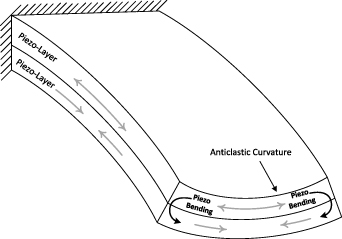
Figure 1. Opposite effects of the anticlastic curvature and the piezoelectric bending moment in the cross section.
Download figure:
Standard image High-resolution imageUsing the effective material coefficients, beam theory gives accurate results for longitudinal deformation in the ideal plane stress and plane strain cases where the Poisson's effect is included [17–19]. There is no analytical solution for actuators in intermediate cases between these two extreme limits even though it is needed. For example, in [20] it was found that the plane stress or plane strain assumptions are not accurate if the width to thickness ratio is between 10 and 1000.
The wider piezoelectric structures with high width/length ratios are extensively used in microactuators [17, 18], microsensors [15] and energy harvesting [21–24]. The transition from narrow to wide orthotropic non-piezoelectric beam was studied by Swanson [6] using the linear plate equations, where the effect of width/length ratio on the cross-section deformation was investigated. The deformation was affected by the width/length ratio because of the boundary conditions at the ends of the structure. This is to be expected from Saint-Venant's principle [25] and is a different effect from the anticlastic deformation studied by Ashwell [3] which is a non-linear effect of a beam in pure bending.
Since there is no realistic estimation of the cross section deformation of a piezoelectric cantilever actuator in the literature, an analytical solution is developed in this paper to predict the deformation of the cross section. To this end, we have generalized Ashwell's results [3] to a piezoelectric actuator. We use the energy method for deriving the more general equations as we find it conceptually simpler and more suitable for generalization than Ashwell's force balance argument. We consider bending due to a mechanical bending moment and an electrical voltage across the electrodes. The effects on the cross-section deformation are studied and verified by finite element (FE) analysis. To this end we compare to the cross section in the middle of a long structure to secure that the result is not affected by the boundary conditions. In the final section, the effect of the Searle parameter is studied in a multi-layer actuator. While the shape of the cross-section depends on the combination of mechanical loading and electrical actuation we show that it is possible to find a scaling relation between the two which keeps the shape of the cross-section fixed when the width is varied at constant Searl parameter.
2. Analytical solution
The bending and anticlastic curvatures of a rectangular cross section structure are shown schematically in figure 2, where R and  are the bending and anticlastic radius-of-curvatures, respectively. For an arbitrary layered structure including piezoelectric layers, applying a voltage will result in longitudinal deformation u and bending radius-of-curvature R as well as the cross section deformation v and w in the plane of cross section. The cross section deformation is depicted in figure 3.
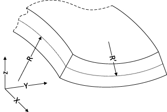
Figure 2. Longitudinal (R) and anticlastic  radius-of-curvature.
Download figure:
Standard image High-resolution image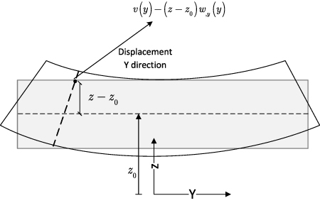
Figure 3. Cross section deformation by assuming small displacement within the cross section.
Download figure:
Standard image High-resolution imageIn order to deal with the deflection along the transversal direction, it is necessary to use plate theory. Assuming a constant bending radius-of-curvature, small strain and allowing large displacement of the axis, the normal strains are defined by modifying the linear classical plate theory as follows:

See the appendix
To find the stresses T, the linear constitutive equations [26]
are used. In equation (3) the material parameters  , ekij
and
, ekij
and  are mechanical stiffness, stress piezoelectric coefficient, and permittivity at constant strain, respectively. Di
and Ek
are the electric displacement and the electric field of the piezoelectric material, respectively.
are mechanical stiffness, stress piezoelectric coefficient, and permittivity at constant strain, respectively. Di
and Ek
are the electric displacement and the electric field of the piezoelectric material, respectively.
The material parameterization in equation (3) is reformulated for a piezoelectric plate in terms of in-plane strains and tractions on horizontal surfaces. Making thin-plate assumptions, we then neglect traction on horizontal surfaces, all shear stresses and all shear strains. This is standard thin-plate theory [14, 27]. It means that the thickness must be significantly smaller than both the transversal and longitudinal dimensions. How much depends on the need for accuracy, but a ratio of 1/20 has been practiced as a rule of the thumb [28]. We treat in-plane electric fields as zero and will also neglect fringing fields at the edges. This requires the lateral dimensions to be significantly larger than the thickness of the piezoelectric layer. In conclusion, we obtain the simplified constitutive equations
The asterisk denotes effective material properties [13, 14, 29].
We consider a structure of n layers where layer number k ∈ {1, 2, ..., n} extends from z = zk − 1 to z = zk
. Further assuming constant electric potential along the length, constant D3, and using  for the voltage across the layer, the electric field
  and electric displacement
  of the kth layer are rewritten as a function of voltage and strain as:
where  is the the thickness of the kth layer. Substituting equations (5) and (6) into the equation (4), the mechanical stresses induced by the voltage at the corresponding layer are given by
and
Finding the governing differential equations considering both curvatures due to the applied voltage and anticlastic deformation is achieved by employing the energy method. For this purpose, the electric enthalpy of a piezoelectric structure [30] is simplified using thin-plate assumptions and integrated over the undeformed configuration volume [31] as:
Substituting the equations (5)–(8) into equation (9) gives electric enthalpy in terms of strain as
where b and L are respectively the width and length of the structure,  and
and  . For the static problem, the kinetic energy part of the Lagranian is zero and Hamilton's principle is reduced to

where We
is the external work done by the applied bending moment Mn
at the tip of the structure. Substituting equations (1), (2) and (10) into the variation of equation (11) and equating the coefficients of variations  , δu,x
,
, δu,x
,  and
and  to zero gives four coupled equations as:
The coefficients of equations (12)–(15) are given by:

and

where  and
and  are geometric parameters. In equations (23) and (24),
  and V is the applied voltage at a reference piezoelectric layer.
  in equation (22) represents the electromechanical coupling.
Equation (11) provides us with two boundary conditions corresponding to the shear force and bending moment at the edge. These are
and
where the mechanical moment  is
is

By solving equation (15) for  to obtain
and substituting it in equation (14), the coupled differential equations are converted to a single ordinary differential equation for the function  :
:
in which the coefficients are given by
and
Using the same procedure, the coupled boundary conditions of equations (27) and (28) are converted to the equations
and
where
Based on the coefficients of the ordinary differential equation (31), the roots of the characteristic equation are given by
The βj s can be real, imaginary or complex values but physically only one of them is feasible. In order to find the physically possible values of βj , the enthalpy equation (10) is rewritten in quadratic form by substituting v,y from equation (30) as
where  is an inconsequential constant term. Based on the equation (40), the stability of the system is achieved if the matrix [D] is positive definite. Therefore
  , D22, and the determinant of the [D] matrix
  must be positive values. The bending radius-of-curvature R is a real value, therefore the stability requires the condition
  which means
  is an imaginary number. Consequently, βj
, j = 1..4, is simplified to the complex values
is an imaginary number. Consequently, βj
, j = 1..4, is simplified to the complex values  with manifest real and imaginary parts. Therefore, the possible solutions of the differential equation (31) are on the form
By applying the boundary conditions (36) and (37), the coefficients can be calculated as
and
where
and  . In equations (45)–(47) the coefficients Ai
, i = 1..4 are
. In equations (45)–(47) the coefficients Ai
, i = 1..4 are


and

The solution given by equation (41) is a generalization of Ashwell's result [3] to a piezoelectric including all electromechanical parameters. Only in the special case of an elastic single-layered structure with a mechanical loading, the current and Ashwell's [3] solution are identical.
For a given tip bending moment and actuation voltage, the structure axis is bent into an arc with radius-of-curvature R along the longitudinal direction. The radius-of-curvature can not be calculated directly, as it is coupled to the other parameters  ,
,  and u,x
. In order to find the solution for the radius of curvature R and the cross section deformation
and u,x
. In order to find the solution for the radius of curvature R and the cross section deformation  , the system of non-linear equations (12), (13), (30), and (41), including
  ,
,  , u,x
and R should be solved. For this purpose, an iterative solution is employed, in which equations (12) and (13) are solved neglecting
, u,x
and R should be solved. For this purpose, an iterative solution is employed, in which equations (12) and (13) are solved neglecting  and
and  firstly. Then
  and
and  are calculated using the solution found for u,x
and R. After that, the solutions of
are calculated using the solution found for u,x
and R. After that, the solutions of  and
and  are substituted in equations (12) and (13). The iteration is repeated until the value for bending radius-of-curvature is converged. This is sufficient because for a given R and Vk
,
are substituted in equations (12) and (13). The iteration is repeated until the value for bending radius-of-curvature is converged. This is sufficient because for a given R and Vk
,  and
and  are determined. The iterative solution process is shown in figure 4 in more details.
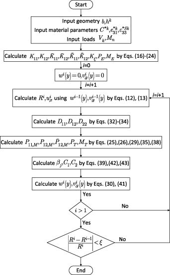
Figure 4. Flow chart for iterative solution of the coupled non-linear equations (12), (13), (30) and (41) for given voltage and tip bending moment.
Download figure:
Standard image High-resolution image3. Results and discussion
In this paper a bimorph and a unimorph configuration are studied, where the bimorph is composed of two layers of 5 µm PZT-5A and the unimorph is made up of the layers of 5 µm glass and 5 µm PZT-5A. We have chosen PZT, because it is a piezoelectric material commonly used in MEMS devices and in commercially available macro-scale devices [32]. The material parameters for PZT5-A were chosen because they are readily available. We considered glass as the structural material because it is widely used in optical structures and has the additional benefit of being isotropic. Hence, we avoid the complications of anisotropy of other relevant materials such as silicon. The material properties are given in table 1.
Table 1. Material properties.
| Parameter | Value |
|---|---|
| PZT-5A | |

| 120.34 |

| 75.18 |

| 75.09 |

| 110.87 |

| −5.35 |

| 1900 |
| Glass | |

| 70 |
| ν | 0.27 |
The convergence of the bending radius-of-curvature is shown in figure 5. In this example the bimorph case is studied, where the width/thickness ratio is taken as 10 and 10 000 for narrow and wide structures, respectively. It is seen that the bending radius-of-curvature converges very fast for both narrow and wide structures. For the wide structure, the convergence is faster than for the narrow structure because the initial cross-section is closer to the final solution. For the extreme narrow and wide structure cases, results of the current formulation converges to the narrow and wide beam solutions of [17]. However, the current formulation applies to a wide range of widths and provides us with the cross-section deformation.
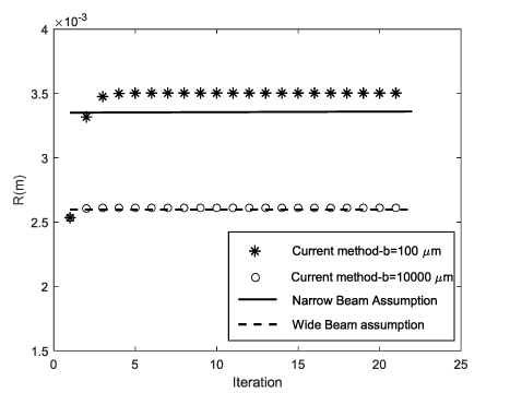
Figure 5. Convergence of the bending radius-of-curvature and comparison of the converged solution with the narrow and wide beam solutions [17].
Download figure:
Standard image High-resolution image3.1. Comparison with numerical solution
We use COMSOL Multiphysics® [33] to verify the proposed formulation. Due to the large deformation of the structure along the length, the geometrically non-linear solver option is chosen. The 3D solid element is employed to model the plate structures of 200, 600, 800, and 1500 µm width. The total thickness/width ratio is low enough to satisfy the thin plate assumptions in section 2. The length of all structures are taken at least twice the width to minimize the effects of the support and tip boundary conditions at the mid span [34]. To apply the mechanical moment to the plate, it is extended at the tip by a shell structure and the Solid-Shell connection of Comsol is employed. The deformation of the cross section located at the mid length of the structure from the finite-element solution is compared with the current analytical solution. In order to reduce the finite element method (FEM) computation time, symmetry of the problem is exploited to model half of the structure. Therefore, the comparison of the analytical and FE results is made for half the cross section. We also performed mesh convergence study, and tested against Ashwell's solution [3] for an elastic structure as a benchmark. The FE model is sketched in figure 6.
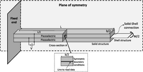
Figure 6. The half symmetric FE model for calculating the cross-section deformation in bending.
Download figure:
Standard image High-resolution imageIn the following we will consider different cases. When we have a nonzero voltage across the piezoelectric, we will refer to the situation as electrical actuation. When we have an external bending moment, we will refer to it as mechanical loading. When we have mechanical loading under short-circuit conditions, we will refer to it as pure mechanical loading. The latter is a choice, we could as an alternative have considered mechanical loading under open-circuit conditions.
3.1.1. Electrical actuation only.
The first set of verifications is performed on the case of pure electrical actuation by applying voltage on both bimorph and unimorph actuators. The cross-sectional shape of a piezoelectric actuator is affected by two opposite deformations while applying an electric field. First is the result of Poisson's effect because of longitudinal bending, and on the other side there exist bending due to the application of the electric field. The cross-sectional deformation of the bimorph actuator is shown in figure 7, in which the voltage of all cases are varied among 3, 15 and 30 V. The consistency of the current analytical solution and the non-linear FE solution results shows that this method is capable of calculating the cross section deformation including anticlastic deformation.
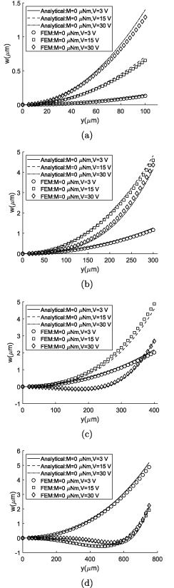
Figure 7. Cross section deformation of the bimorph actuator with electrical actuation and comparison with the FEM: (a) b = 200 µm, (b) b = 600 µm, (c) b = 800 µm, (d) b = 1500 µm.
Download figure:
Standard image High-resolution imageIn all cases, the cross sections are deformed in the opposite direction of the anticlastic deformation due to the existence of the moment applied by the electric field. As the width and the voltage of the actuator is increased, the bending radius-of-curvature is decreased for the same electric field, and as the result the Searle parameter is increased. For higher Searle parameters, it is seen that deformation is neutralized at the center of the cross section. Despite higher actuating moment with higher voltage, it is observed that the neutralization force for higher Searle parameter is dominant and in wider structures, the cross section deformation is close to flat, except at the edges.
A comparison of the bending radius-of-curvatures calculated by using the current method, the narrow beam assumption [17] and FEM shows that the current method gives results closer to FEM than the narrow beam solution for the case of bimorph actuator with the width 200 µm. The bending radius-of-curvature of the current formulation and the narrow beam assumptions are calculated as 3.504 and 3.350 mm, respectively.The bending radius-of-curvature from the FE solution is 3.718 mm which is 9.9% and 5.7% higher than the narrow beam assumption and the current method, respectively.
In the case of unimorph actuator, the same behavior as the bimorph actuator is observed. As shown in figure 8, the results of the analytical method well agrees with the results of the FE ones, which verifies the current formulations for the unimorph configuration, as well.
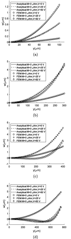
Figure 8. Cross section deformation of the unimorph actuator with electrical actuation and comparison with the FEM: (a) b = 200 µm, (b) b = 600 µm, (c) b = 800 µm, (d) b = 1500 µm.
Download figure:
Standard image High-resolution image3.1.2. Electrical actuation and mechanical loading.
As mentioned in section 1, the cross-section deformation due to pure mechanical loading has been widely studied and verified by the researchers. In the previous section, it was shown that applying an electric field on the piezoelectric layer leads to an electromechanical deformation that is larger than the deformation due to Poisson's effect. In this section, the cross-section deformation is studied by applying both mechanical tip moment and electric field to investigate these two opposite curvatures.
The results of bimorph and unimorph actuators are shown in figures 9 and 10, respectively. The results of both cases are consistent with those from FE, although a bit discrepancy is observed in wider structures. Applying both mechanical loading and electrical actuation, the convergence time of FE solution is dramatically increased in wider structures which is the consequence of solving a highly non-linear problem. As an example, the computational time for the case of the widest bimorph structure b = 1500 µm with maximum mechanical loading and electrical actuation voltage is 3 h and 58 min in Comsol, while it takes 2.65 s for our solution on the same computer. Despite the fast solution of the current analytical method, it is possible to predict the behavior of the cross section very well in narrow and wide structures, and even in transition as shown in figures 7–10.
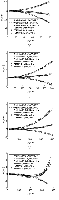
Figure 9. Cross section deformation of the bimorph actuator with electromechanical loading and comparison with the FEM: (a) b = 200 µm, (b) b = 600 µm, (c) b = 800 µm, (d) b = 1500 µm.
Download figure:
Standard image High-resolution image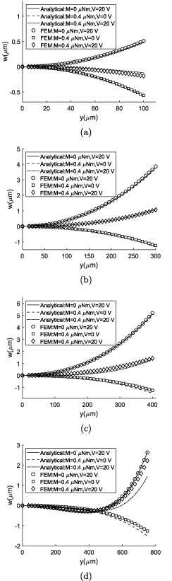
Figure 10. Cross section deformation of unimorph actuator with electromechanical loading and comparison with the FEM: (a) b = 200 µm, (b) b = 600 µm, (c) b = 800 µm, (d) b = 1500 µm.
Download figure:
Standard image High-resolution imageIn all cases of pure mechanical loading, the anticlastic curvature is observed. The anticlastic deformation is not neutralized in these examples as the applied mechanical moment is not high enough to increase the Searle parameter. As shown in figures 9 and 10 the cross sections are deformed in different directions by applying either the pure mechanical loading or electrical actuation. Therefore, it is possible to observe flat plate by applying appropriate values of moment and voltage, even in narrow structures. Applying the mechanical and electrical loads simultaneously will result in lower bending radius-of-curvature and higher Searle parameter accordingly. Therefore, the neutralizing force is prominent in wider structures and the deformation is flattened at the central zones in the case of b = 1500 µm.
3.2. Cross section flattening
It is seen in the previous section that in a piezoelectric actuator, in addition to the Searle parameter, the relative contributions from mechanical loading and electrical actuation play an important role in the cross-section deformation. When both contribute to decreasing the bending radius-of-curvature, they oppositely affect the cross-section curvature.
The opposite effect of the electrical and mechanical loadings can help us to find the load values in order to neutralize the cross section deformation. For this purpose an iterative numerical solution scheme is implemented to find the the bending moment in which w(0) approaches w(b/2) at a given voltage. In this solution scheme, the voltage is kept constant, and the method of bisection is used to find the bending moment that satisfies  . The details of the solution procedure are shown in the flow chart of the figure 11. Figures 12 and 13 show that the cross section deformation can be neutralized by applying both voltage and moment in the bimorph and unimorph actuators, respectively.
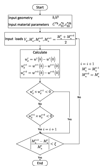
Figure 11. The method of bisection flow chart for finding the neutralization bending moment at a specified actuation voltage.
Download figure:
Standard image High-resolution image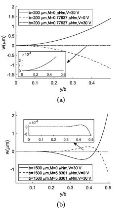
Figure 12. Competing effects of the electrical and mechanical loading on the cross section deformation and cross section neutralization by combining both loadings in bimorph actuators: (a) b = 200 µm (b) b = 1500 µm.
Download figure:
Standard image High-resolution image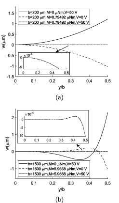
Figure 13. Competing effects of the electrical and mechanical loading on the cross section deformation and cross section neutralization by combining both loadings in unimorph actuators: (a) b = 200 µm (b) b = 1500 µm.
Download figure:
Standard image High-resolution imageIn the case of pure mechanical model, any bending moment results in anticlastic deformation, and in a wider structures the anticlastic deformation near the center of the cross section is much smaller than the edges. A piezoelectric actuator behaves in a different way, because it is possible to reduce the deformation in the whole cross section for specific values of applied voltage and mechanical moment. Although it is not possible to make the cross section completely flat as shown in the insets of figures 12 and 13, it can be neglected in comparison with the pure mechanical loading or electrical actuation.
3.3. Searle parameter in piezoelectric actuators
Investigating the moment, voltage and the combination of both loadings indicated that the Searle parameter is an important parameter in cross-section deformation also of piezoelectric actuators. In this section this parameter is studied in more details in actuators of widths b = 200 and b = 1500 µm representing narrow and wide structures.
The cross section deformation of structures are shown in figure 14, where the bending radius-of-curvature is kept constant by tuning the voltage and moments for each width. In each case of the narrow and wide structure, the Searle parameter is constant as the radius-of-curvature, width and thickness are the same. In addition to the Searle parameter, the type of loading is an important parameter affecting the cross section deformation as shown in figures 14(a) and (b). As expected, for higher values of Searle parameter the cross section deformation is neutralized near the center of the cross section. We can keep radius-of-curvature of the case b = 1500 µm equal to b = 200 µm by tuning the applied loading. In figure 15 the radius-of-curvature of the wide structure is 3550 µm, which is the same as the R of the narrow structure in figure 14(a). Comparing both figures, shows the effect of the Searle parameter in neutralization of the wider structure, even with the same radius-of-curvatures. Therefore, the same longitudinal deformation (radius of curvature) might be achieved by applying different combination of loadings, but the cross section deformation is dependent on the Searle parameter and the type of loading.
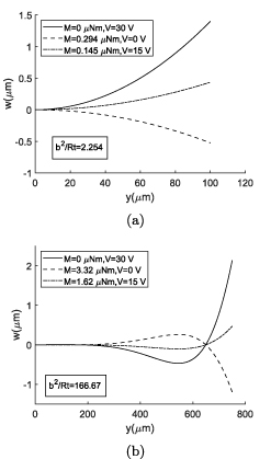
Figure 14. The effect of the type of loading on the cross section deformation of the bimorph actuator with the same bending radius-of-curvature R for the same widths: (a) b = 200 µm and R = 3550 µm, (b) b = 1500 µm and R = 2700 µm.
Download figure:
Standard image High-resolution image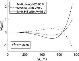
Figure 15. The effect of the type of loading on the cross section deformation of the bimorph actuator with the same radius-of-curvature as figure 14(a), R = 3550 µm and b = 1500 µm but different Searle parameter.
Download figure:
Standard image High-resolution imageAs the Searle parameter is playing an essential role in the cross section deformation of piezoelectric actuators, we dig into equations to find this parameter. First of all, from equation (39) α1 and α2 are decomposed into the following forms:
where  and
and  are functions of the layer stack, material parameters and Hk
which is defined as the ratio of each layer's thickness to the structure thickness t. Therefore, for the same layer stack α1 and α2 are dependent on the bending radius-of-curvature and the structure thickness. Based on this definition, the cross-section deformation of equation (41) can be rewritten as
are functions of the layer stack, material parameters and Hk
which is defined as the ratio of each layer's thickness to the structure thickness t. Therefore, for the same layer stack α1 and α2 are dependent on the bending radius-of-curvature and the structure thickness. Based on this definition, the cross-section deformation of equation (41) can be rewritten as
It is seen in equation (54) that the Searle parameter appears by normalizing the independent variable y by the width b. The equation (54) is similar to that one derived by Ashwell [3].
If the width of an arbitrary actuator is multiplied by a positive value N, to keep the Searle parameter fixed, the bending radius-of-curvature should be multiplied by N2. Consequently, if the coefficients C1 and C2 are unchanged, the cross-section deformation of equation (54) for the width Nb should be the same as the one of the width b. This condition requires PT and MT to be unchanged. Regarding equation (12), if R is multiplied by N2, the axial strain u,x is divided by N2. Based on equations (35) and (38), fixed values of PT and MT forces the value of the voltage divided by N2. It means that in the case of pure electrical actuation, if the width is multiplied by N, the electric potential must be divided by N2 to get the same shape of cross-section deformation. Referring the equation (13) gives the scaling of the mechanical moment loading 1/N for a fixed cross-section deformation. Hence, it is concluded that if the width is multiplied by N, the cross-section deformation of the actuator is unchanged if the mechanical moment Mn and the electric potential V is scaled by 1/N and 1/N2, respectively. This conclusion is shown for small and large values of Searle parameter in figures 16 and 17 for bimorph and unimorph actuators, respectively. It shows that the deformation of the cross-section versus y/b is unchanged when changing the width provided that the mentioned load scaling rule is obeyed.
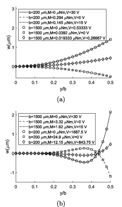
Figure 16. Identical cross-section deformation of bimorph actuators with different widths by applying the load scaling rule (a) Searle parameter = 2.26, (b) Searle parameter = 166.69.
Download figure:
Standard image High-resolution image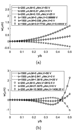
Figure 17. Identical cross section deformation of unimorph actuators with different widths by applying the load scaling rule (a) Searle parameter = 1.95, (b) Searle parameter = 139.06.
Download figure:
Standard image High-resolution image4. Conclusion
The cross section deformation of a piezoelectric actuator is affected by the Poisson effect and the electromechanical bending due to the applied voltage. While applying pure mechanical loading, the anticlastic deformation is observed. In contrary, while applying pure electrical actuation, the electromechanical bending in the cross section is dominant and the deformation is opposite the anticlastic deformation. Applying both mechanical and electrical loads, the cross section deformation is induced by both anticlastic deformation and the electromechanical bending simultaneously. Therefore the cross section is affected by these two opposing deformations, and it can be flattened by applying proper values of voltage and mechanical moment.
The same as the mechanical loading, when electrical actuation is applied to a piezoelectric actuator, the deformation of the cross section is neutralized for larger values of Searle parameter. Interestingly, the Searle parameter is an important parameter dictating the cross section deformation in piezoelectric actuators. For the case of combination of electrical and mechanical loadings, a scaling rule is proposed to fix the cross section deformation for different widths of the actuator. If the width is multiplied by N, the voltage and the mechanical moment must be divided by N2 and N, respectively to keep the cross section deformation versus y/b unchanged. The Searle parameter is also kept fixed by employing this scaling rule.
Data availability statement
The data that support the findings of this study are available from the corresponding author upon reasonable request.
Acknowledgment
This work was supported by the Research Council of Norway through Grant No. 273248.
Appendix A.: Kinematics of the structure
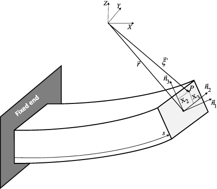
In this section, the kinematics of the structure is used to derive the components of the strain tensor. Figure A1 shows a deformed structure with an orthogonal coordinate system  normal to the cross section at position s along the deformed structure. If the cross section did not deform in bending, the position of an arbitrary point P on the cross section would be

where  is the position of the origin of the local coordinate system. To account for the deformation of the cross section, we introduce local displacements (v, w) along
  within the cross-section. The position of the point P after deformation is then given by

Figure A1. Cross section of the structure after deformation.
Download figure:
Standard image High-resolution image
We can use the vector  to derive the Green-Lagrange strain tensor as [35]:
in which
The vector differentials to s is given as [36]:
where ρ1, ρ2 and ρ3 are the twisting curvature around  and the bending curvature around
  and
and  , respectively. Due to the loading conditions, ρ3 and ρ1 are zero. The axial strain εa
is introduced as:
, respectively. Due to the loading conditions, ρ3 and ρ1 are zero. The axial strain εa
is introduced as:
which results in:
Substituting equations (A7), (A8) and (A10) into equation (A4) gives:
Substituting equations (A5), (A6) and (A11) into equation (A3) gives the components of the strain tensor as:
In this section, we have used (X1,X2,X3) to derive the strain tensor, because it is more convenient to follow the indicial notations. Now, we can relate the equations of this section to those ones in section 2 by replacing  with
with  . Assuming small displacement within the cross section as:

neglecting the higher order terms of  and εa
, and in addition making small-strain assumptions, the strain tensor elements become:
and εa
, and in addition making small-strain assumptions, the strain tensor elements become:


where  and
and  . The shear strains equations (A23) and (A24) vanish, as v and w are not x-dependent.