
Abstract
Mechanical vibrations from heavy machines, building structures, or the human body can be harvested and directly converted into electrical energy. In this paper, the potential to effectively harvest mechanical vibrations and locally generate electrical energy using a novel piezoelectric-rubber composite structure is explored. Piezoelectric lead zirconate titanate is bonded to silicone rubber to form a cylindrical composite-like energy harvesting device which has the potential to structurally dampen high acceleration forces and generate electrical power. The device was experimentally load tested and an advanced dynamic model was verified against experimental data. While an experimental output power of 57 μW cm−3 was obtained, the advanced model further optimises the device geometry. The proposed energy harvesting device generates sufficient electrical power for structural health monitoring and remote sensing applications, while also providing structural damping for low frequency mechanical vibrations.
Export citation and abstract BibTeX RIS

Original content from this work may be used under the terms of the Creative Commons Attribution 4.0 license. Any further distribution of this work must maintain attribution to the author(s) and the title of the work, journal citation and DOI.
1. Introduction
Electrical energy generation is paramount in a fully electrified world powering transport, lighting, computing and health. In order to meet the electrical energy demands, unexplored and abundantly available mechanical energy can be converted directly into electrical energy. The harvested electrical energy provides a route for the realisation of autonomous and self-powered, low-power electronic devices [1]. These devices have been successfully implemented as electromagnetic shock absorbers for energy harvesting [2] or for tire pressure monitoring [3]. However, when developing energy harvesting devices several principles can be applied such as electromagnetic induction [4], triboelectric phenomena [5], or the piezoelectric effect [6]. The piezoelectric effect is of particular interest because piezoelectric materials directly convert mechanical energy into an electric charge when subjected to mechanical stress. On the other hand, the most powerful piezoelectric materials such as barium titanate oxide (BaTiO3) or lead zirconate titanate are stiff and brittle ceramics [6] and only a few piezoelectric polymers and co-polymers exist including polyvinylidene difluoride (PVDF) and nylon. When using piezoelectric ceramics various challenges on the device level arise such as, small mechanical designs, material selection and electrical circuits which usually limit the potential of piezoelectric energy harvesting devices. Various mechanical designs exist using cantilever designs [7], bending designs [8] or simply using bulk materials directly for random mechanical impact or continuous low frequency vibrations [9]. It is possible to harvest random mechanical impact from raindrops [10], traffic induced broadband bridge vibrations [11] or mechanical energy from human motion [12], with bulk materials or sandwiched structures [13]. However, usually multiple design challenges exist on a device level when tailoring piezoelectric materials towards a specific mechanical energy source. For this reason, advanced piezoelectric geometries for specific mechanical frequencies and forces are increasingly being developed. Examples for advanced piezoelectric geometries are piezoelectric fibres embedded into a bi-stable composite [14] or woven piezoelectric yarn [15]. Other advanced piezoelectric geometries are ring-type transducers [16] or piezoelectric tubes [17, 18] for structural health monitoring or fluid control [19]. For energy harvesting applications, tubular and cylindrical designed piezoelectric devices use a cylindrical shell with layered piezoelectric material [20] or piezoelectric patches attached to the shell [21]. However, a direct utilisation of piezoelectric tubes for energy harvesting remains difficult due to the stiff and brittle nature of ceramics. For this reason, this paper proposes a piezoelectric tube directly attached to a rubber material as a composite piezoelectric energy harvesting structure. The structure combines powerful piezoelectric ceramics with soft and flexible silicone-rubber creating a piezoelectric energy harvesting device from two dissimilar materials, each with opposing mechanical properties. The combination of high energy harvesting performance in a soft and flexible design provides a novel route to exploiting mechanical energy utilising a simple device. Similar, but more complex designed metal frame structures haven been modelled [22]. Hence, the silicone-rubber used in the energy harvesting device is an ideal material for simple mechanical mounts (buffers, bump stops, bushings) as well as the main component of air inflated tyres. In addition, rubber has excellent elastic properties for vibration damping (similar to a mechanical spring) and shields objects from mechanical impact and/or vibrations, and further provides thermal insulation. Due to the combination of a soft and hard material, the piezoelectric energy harvesting device combines vibration damping as a passive form of mechanical isolation while continuously generating electrical energy from otherwise unused energy from mechanical vibrations.
This paper fully discloses the proposed piezoelectric-silicone structure, provides experimental results of the performance, and validates this using an advanced dynamic model to optimise the geometry towards maximum power output. Finally, this paper demonstrates a feasible piezoelectric energy harvesting device utilising off-the-shelf components and providing a route to cost-effective recovery of mechanical energy on a small scale.
2. Methodology
Piezoelectric materials are solid crystal or crystalline materials exhibiting an electric dipole moment or polarisation P (C m−2). The polarisation of piezoelectric materials is defined by the charge density and surface area and follows [23]:
for the charge density C (C) and material surface area A (A). If the piezoelectric material is exposed to a mechanical force the level of polarisation changes proportionally to the applied mechanical stress. This change in polarisation also leads to a surface effect, where on opposite electrodes electric charge is attracted or repelled by the material's change in polarisation creating an electrical potential difference. This potential difference is available for discharge as an electric voltage. The open-circuit voltage V (V), or electric field E (V m−1), response from a piezoelectric device results from the applied mechanical stress and is defined as [6]:
for a given force F (N m−1), area A (m2), thickness t (m), permittivity  (F m−1) and material specific piezoelectric strain coefficient d33 (C N−1). The piezoelectric strain coefficient is directional, experiencing strong changes in polarisation parallel to the applied mechanical force. When used in an energy harvesting environment with a resistive external electrical load, the generated voltage V from the piezoelectric device determines the electric current flowing through the external resistive load R (Ω) and the corresponding power as follows [6]:
However, since most piezoelectric generators experience vibrations, the mechanical force (F) changes direction introducing alternating currents (AC) through the external load. The generated voltage here can be approximated by the root mean square (rms) value for a sinusoidal piezoelectric voltage response Vrms [24]. Subsequently, the maximum power P from the piezoelectric energy harvesting device attached to a resistive impedance matched external electric load Rl (Ω) is as follows [25]:
with:
and source capacitance C (F) of the piezoelectric device. The capacitance of the piezoelectric device can be approximated in rough analogy to a parallel-plate capacitor with the surface area of the electrodes A, piezoelectric material permittivity , and material thickness t as follows:
According to figure 1, a piezoelectric tube can be radially poled through the wall thickness t with inner and outer electrodes. Radially applied mechanical forces then creates the external voltage (V) across the two electrode terminals available for discharge. The employed piezoelectric Lead (Pb) Zirconate (Zr) Titanate (Ti)—PZT tube was sourced from APC International Ltd (US) as a ring transducer with an inner diameter of 4.8 mm, an outer diameter of 6.35 mm and a length of 6.35 mm. The transducer was manufactured using two 12 μm thick silver electrodes and provided an electrical capacitance of C = 2500 pF. The soft type PZT materials employed in this study have a piezoelectric strain coefficient of d33 = 350 N C−1 and a relative permittivity of 33 = 1800 [26]. The PZT exhibits superior piezoelectric properties compared to other readily available piezoelectric materials, such as BaTiO3 or PVDF, when considering strain deformations (ΔL) of 0.1% [27]. Despite environmental concern with lead-based material, PZT is unlikely to be replaced in the foreseeable future due to the complex requirements of piezoelectric applications [28]. Hence, when harvesting physical impact with a high mechanical force this ceramic type of piezoelectric material is too hard and too brittle leading to material damage and potentially device failure. In order to overcome this problem, we propose a piezoelectric-silicone rubber cord structure for vibration energy harvesting utilizing indirect, or reactive, mechanical forces. For an axial mechanical force, polymeric elastomers can experience high reversible strain ΔL deformations in the order of up to 5600% leading to an equally high radial strain deformation ΔR [29]. If a silicone cord is fed through the piezoelectric tube the radial strain deformation ΔR is clamped transferring mechanical force to the tube. The force needed for a reversible strain ΔL deformation is weakly defined by [30]:
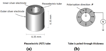
Figure 1. Piezoelectric tube as ring transducers radially polarized across wall thickness (a) and electric circuit connection for voltage signal measurements (b).
Download figure:
Standard image High-resolution imageand governed by the force (F), geometry (L, A) and material specific Young's Modulus E. According to equation (6), materials with a small Young's Modulus experience large reversible deformations. Large reversible deformations also translate into large radial strain deformations, or swelling, of materials perpendicular to the direction of loading. The swelling behaviour is defined for isotopic cylindrical materials by Poisson's ratio as follows:
for a defined axial strain ΔL and radial strain ΔR. According to equations (6) and (7), materials with a high Poisson's ratio under large compressive forces exhibit large reactive forces in the form of radial strain. This implies the piezoelectric-silicone structure for vibration energy harvesting utilizes indirect, or reactive, mechanical forces by swelling. Figure 2 shows the reversible strain deformation of the piezoelectric-silicone structure under an axial loading force. The reactive swelling force of the silicone cord is constrained by the piezoelectric tube transferring mechanical energy onto the piezoelectric tube's inner wall. The piezoelectric tube under force directly exhibits a voltage, utilizing the longitudinal extension mode (3–3) of the piezoelectric-tube, which is available for discharge across an external electric load (equation (3)). In most energy harvesting applications, the quality of the mechanical source energy (force, frequency and acceleration) is not adjustable, for which reason the design of energy harvesting devices is limited to mechanical and geometrical optimisations and material selection. Hence, the aim of the analysis is to maximise swelling as a result of external compression or axial loading forces. As commercially available piezoelectric tubes are rare and expensive, we optimised the length of the silicone cord for maximum swelling and therefore maximise secondary, or reactive, mechanical forces transferred onto the piezoelectric tube. Due to the complex geometry and material mix, it is extremely difficult to calculate the internal force and stress experienced inside the materials and at the interfaces between the silicone-cord and the piezoelectric tube. However, in most piezoelectric energy harvesting devices the mechanical force (F) as well as the electric field (E) changes direction necessitating transient analysis. The transient response of the piezoelectric-silicone structure in figure 2 can be described by the equation of motion in matrix form as follows [31]:

Figure 2. Piezoelectric-silicone structure for vibration energy harvesting (a) and visualised under axial mechanical load (b).
Download figure:
Standard image High-resolution imagefor displacement x, mass matrix M, D and K, and electric charge q (C). Due to the continuously changing mechanical force, the complex structure in figure 2(b) exhibits a dynamic response with complex vibration modes and resonance. Thus, the proposed experiment compares direct measurements with numerical finite element modelling (FEM) results for generated power and available energy under various transient forces.
3. Dynamic testing
This paper reports on dynamic testing of piezoelectric energy harvesting devices under controlled laboratory test conditions, in order to approximate energy harvesting performance under real world conditions. While most accelerations, such as human walking, are below 10 g [32], forced accelerations in tyres can reach up to 5000 g [33]. Since representative natural accelerations and vibrations are challenging to re-create, this paper utilised constant accelerations and continuous vibration sources below 50 Hz in order to describe a reproducible energy harvesting set-up and realistically test energy harvesting devices [34]. Vibrations below 50 Hz usually coincide with low acceleration levels around 2–3 g for example in human walking [35]. According to figure 3, a signal generator is driving a sinusoidal voltage into an LDS PA25E power amplifier which supplies power to a mechanical shaker V201-M4-CE. The excitation of the mechanical shaker creates an axial force acting at the two end surfaces of a cylindrical clamped silicone rubber cord or piezoelectric-silicone energy harvesting device. The piezoelectric-silicone device is mechanically load tested under a constant acceleration magnitude of 1 g and 2 g to create controlled structural forces and deformations. Based on the reactive radial strain (equation (7)) the piezoelectric tube open circuit voltage is directly measured by a high input impedance oscilloscope probe set-up with a sampling rate of 50 MHz. The acceleration excitation was measured using a 10 g accelerometer data acquisition device with a sampling rate of 10 kHz maintaining 1 g and 2 g excitation acceleration throughout the test. The device was tested at slow frequencies between 10 and 50 Hz while the experimental data was continuously recorded over a minimum of six cycles with a combined calculated error for the peak-to-peak voltage (Vpp) of ±10% at 1 g and 2 g acceleration levels. Following Newton's second law of motion the applied force is maintained constant across all frequency measurements by adjusting the acceleration at the shaker. The shaker was operating parallel to the earth's gravitational force in order to avoid double impact and radial forces on the test specimen. According to table 1, the tested piezoelectric-silicone rubber energy harvesting device shows considerable differences between the employed silicone rubber cord and the PZT tube. The silicone cord is made of 95% silicone rubber compound, 2% organic peroxide mixture, 2% iron oxide, and 0.5% organopolysiloxane, and sourced from Sealmasters Ltd (UK) [36]. The Poisson's ratio of the silicone rubber cord is eight orders of magnitude greater than that of the PZT, indicating its greater flexibility. The Young's modulus of 130–150 GPa for PZT indicates very hard mechanical properties compared to 5 MPa of silicone rubber indicating very light and soft properties [37]. The assembly of these substantially different materials in a piezoelectric-silicone structure requires the experiment to be reproducible and simple in order to derive the energy harvesting capabilities of the device tested. For this reason, the proposed materials were tested at room temperature accounting for the Curie point of PZT below 300 °C [26] and the transition temperature for silicone of over 400 °C [38]. This leaves sufficient space for energy harvesting applications at elevated temperatures, which could be evaluated in subsequent studies.
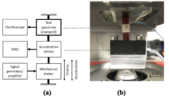
Figure 3. Energy harvesting test set-up equivalent diagram (a) with signal flow direction indicated by arrows and mechanical links illustrated by solid lines. The picture (b) shows a vertical orientated clamped energy harvesting device.
Download figure:
Standard image High-resolution imageTable 1. Material properties of piezoelectric-silicone rubber energy harvesting device.
| Material | Young's Modulus (GPa) | Poisson ratio (–) | Density (kg m−3) | Relative permittivity (C m−2) |
|---|---|---|---|---|
| Silicone | 5 | 0.470000000 | 1.3 | 2.9 |
| PZT | 130–150 | 0.000000031 | 7500.0 | 1800.0 |
4. Finite element model
An advanced FEM model was developed using elastic elements based on the basic law of motion and coupled with the reactive forces of piezoelectric theory. Due to the high level of directional non-linearity with piezoelectric materials, the coupled-field, harmonic and transient response analysis was carried out in ANSYS Parametric Design Language. The analysis in ANSYS allows for optimisation of the mechanical design and the material selection. The ANSYS model is comprised of two different volumes representing the proposed piezoelectric-silicone rubber energy harvesting device. Based on the material properties in table 1, the first volume is a cylindrical silicone-rubber cord meshed in Solid186, bonded to a second piezoelectric PZT tube-shape volume, meshed in Solid227. The commercial FEM solvers facilitate the analysis of the rotational, symmetrical, cylindrical structure by transforming the piezoelectric compliance matrix from a geometrical Cartesian (x, y, z) system into a geometrical cylindrical (r, θ, z) coordinate system, where the direction of polarization P is taken to be parallel to the radial direction r, or equivalent to axis 3 in the Cartesian coordinates. Hence, the Cartesian piezo-ceramic geometry follows [19]:
with radius r, angular coordinate ϑ, and cylinder height z. The silicone-tube cord and piezoelectric tube model exhibits longitudinal (w) and radial (u) displacement and stress while torsion is constrained (v). Hence, a structural harmonic analysis, at constant excitation forces (F) for 1 g and 2 g acceleration levels, was conducted based on the following boundary conditions as input parameters:

with:
u(r) = free;
v(ϑ) = 0;
w(z) = F × sin(2 × π × f); for sinusoidal drive frequencies between 10 and 50 Hz and open circuit piezoelectric voltage. With the longitudinal (z), radial (r), and electrical (Er ) degree of freedom, the vibration modes and resonance frequencies are computed in ANSYS. Due to the relatively low frequency applied in the experiment, the dissipation energy for cycling strain loads inside the material was neglected in the model because no temperature changes were observed during the experiments. In addition, hyperplastic effects and/or viscoelastic effects were also neglected in the model for simplicity. The direction of polarization is taken to be parallel to the z or axis 3 in the Cartesian coordinate description of piezo-ceramic geometry. Hence, the anisotropic compliance matrix S (inverse of Young's modulus) was reduced and transformed as follows [19]:
together with the shear strain γzr
and electric field E (V). Subsequently, a piezoelectric strain coefficient of d33 = 350 N C−1 and a relative permittivity of 33 = 1800 was used for the PZT model as well as the elastic compliance c (1010 N m−2) as follows [39]:
The transformed piezoelectric matrix acts together with the compliance matrix, along with the applied cylindrical loads, in the cylindrical coordinate system, which provides the piezoelectric voltage based on the experienced strain.
Figure 4 illustrates, the three-dimensional piezoelectric-silicone energy harvesting structure that was modelled in ANSYS as a longitudinal-section of figure 2. The longitudinal-section model enables the analysis of the mechanical principles inside the silicone cord revealing the stress and strain distribution inside the material which is significantly more difficult to physically analyse. Subsequently, the model piezoelectric-silicone rubber device dimensions (figure 2) are optimised towards a maximum open circuit voltage for a variable silicone-rubber cord length as follows:


Figure 4. Meshed piezoelectric-silicone longitudinal-section three-dimensional model in ANSYS (colours represent displacement and voltage under mechanical load).
Download figure:
Standard image High-resolution imageFor a short silicone-rubber cord length, the swelling force is concentrated along the centre of the piezoelectric tube and less so towards the unconstrained edges. For every change in stress concentration, the computed voltage is then extracted and validated against experimental data. Then a longitudinal-section stress analysis is conducted in order to determine mechanical stress distribution.
5. Results and discussions
The disclosed piezoelectric energy harvesting device was bench tested and the FEM model was verified against the obtained experimental data. According to figure 5, the energy harvesting device generates an open circuit voltage peak-to-peak Vpp (V) of 11.5 V at 10 Hz driving frequency and 1 g excitation acceleration (Er in equation (10)). When doubling the excitation acceleration to 2 g at 10 Hz the open circuit voltage nearly doubles to 21.0 V. This loosely linear relationship between open circuit voltage and acceleration excitation was present for driving frequencies of up to 30 Hz. At 30 Hz the open circuit voltage at 1 g is 3.3 V and 6.4 V at 2 g. For higher frequencies over 30 Hz the measured open circuit voltage is no longer proportional to the increases in acceleration excitation and the device only generates a voltage of 1.9 V at 2 g compared to 1.4 V at 1 g at 50 Hz. The FEM model consistently overestimated the peak voltage with an error of up to 2.7% at frequencies below 30 Hz at 1 g and up to 15.8% at frequencies below 35 Hz at 2 g. The error is indicated in figure 5. For the measured open circuit voltage in figure 5, it is possible to calculate the available power of the energy harvesting device (equation (4)).
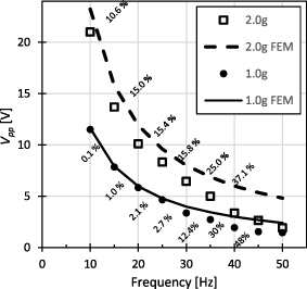
Figure 5. Peak-to-peak open circuit piezoelectric-silicone rubber device voltage response for 1.0 g and 2.0 g excitation acceleration (indicating the FEM error in %).
Download figure:
Standard image High-resolution imageAccording to equation (4), the optimal load resistance is a function of the driving frequency. Subsequently, the optimal resistances for the investigated frequency range are between 6.37 MΩ (at 10 Hz) and 1.27 MΩ (at 50 Hz). However, since piezoelectric AC is hardly used in practical energy harvesting applications external rectifier circuits are necessary [40]. These rectification circuits are usually assembled of discrete components in their most basic configuration with an input impedance < 1 MΩ [41]. Hence, figure 6(a) shows the measured peak power (equation (3)) at 1 g and figure 6(b) shows the measured peak power at 2 g for a 0.2–1 MΩ external load resistance, providing a more realistic estimate of the energy harvesting power. At this impedance and frequency range rectification circuits can operate effectively [42]. At 1 g a power of 8.5 μW is dissipated at 5 Hz and 1 MΩ. According to equation (3), the dissipated power P for lower external load resistances R and higher frequencies appears to decrease linearly. However, at 2 g in figure 6(b) a power of 45.4 μW is dissipated at 5 Hz and 1 MΩ and decreases for smaller resistances. The dissipated power also decreases for higher frequencies since the duration of the force is shorter (equation (2)).
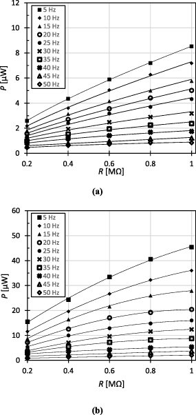
Figure 6. Generated peak-power for 0.2–1 MΩ external resistive load at 1 g (a) and 2 g (b).
Download figure:
Standard image High-resolution imageFigure 7 shows a calculated, and impedance matched (equation (4)), Prms power output of 86.5 μW (specific energy density of 57 μW cm−3) obtained at 2 g acceleration excitation and at the lowest frequency measured of 10 Hz. Due to the AC characteristics of the piezoelectric energy harvesting device the average Prms in equation (4) provides a reasonable estimate of the ideal performance of the proposed device for high matched resistances Rl of up to 10 MΩ. Due to the squared voltage expression in equation (4), the peak power of 26 μW (specific energy density of 17 μW cm−3) at 1 g is considerably lower than the peak power of 86.5 μW at 2 g, demonstrating the significance of open-circuits voltage improvements for the energy harvesting device performance. However, for increasing drive frequencies the power gains resulting from the voltage improvements diminish slowly. At 50 Hz the average power at 1 g is 2 μW compared to 3.6 μW at 2 g, indicating that the proposed device is more suited towards low frequencies and high acceleration excitation. The measured open circuit voltage is compared with the calculated open circuit voltage of the FEM model in figure 5. The calculated open circuit voltage has a reasonable accuracy at low excitation acceleration and frequencies below 25 Hz. However, the calculated voltage response of 5 V at 50 Hz and 1 g is significantly higher than the experimental voltage response of 1.92 V. Hence, the conducted FEM model gradually loses accuracy with increasing frequencies and accelerations. A lack of viscoelastic and heating effects in the FEM model potentially leads to a discrepancy between measured open circuit voltage in the experiment and computed open circuit voltage in the FEM model. These effects are more likely to negatively affect a soft material like rubber in the examined high frequency energy harvesting environment, compared to a hard piezoelectric ceramic (table 1). In addition, the calculated harmonic and transient response of the model potentially includes complex dynamic changes within the energy harvesting device. Hence, the proposed model provides a good reference for low frequency and low excitation acceleration applications and optimisations. In order to optimise the device performance at low frequencies and low excitation accelerations the effect of silicone-cord length on the design needs to be analysed (equation (12)). The length of the silicone cord is optimised based on the best possible FEM model accuracy at 10 Hz for 1 g and 2 g. According to figure 7, the peak open circuit voltage of the energy harvesting device is seen for a 13 mm silicone cord length with a maximum voltage of 17.6 V. At 2 g excitation acceleration, the maximum open circuit voltage is 38 V for the same 13 mm silicone-cord length. According to figure 8, the optimal length of the silicone-cord for 1 g and 2 g of excitation is 13 mm with rapidly decreasing performance for shorter and longer silicone-cord lengths. For higher excitation levels the peak voltage flattens out more rapidly than for lower excitation levels. For short cord lengths below 13 mm, this highly non-linear performance is limited by the swelling area of the silicone cord. Below 10 mm, axial forces on the piezoelectric tube are higher than the applied radial forces, creating electric fields perpendicular to the electrodes (Ez in equation (10)).

Figure 7. Peak power of piezoelectric-silicone rubber device voltage response for 1.0 g and 2.0 g excitation acceleration.
Download figure:
Standard image High-resolution imageFigure 9(a) shows a FEM mechanical stress analysis for a 10 mm silicone rubber cord length longitudinal-section at 1 g and 10 Hz with high stress concentrations at the piezoelectric tube edges (figure 4). The colour bar indicates a homogeneous stress level across the silicone-rubber of 4.83 MPa which is close to the material limit of 5 MPa. Compared to the undeformed material edges, substantial swelling is present where the silicone-cord is unconstrained by the piezoelectric tube. However, the piezoelectric tube experiences substantial stress at the tube edges due to non-uniform loading effects from the swelling rubber close to the mechanical limit (table 1). Compared to a 15 mm long silicone cord figure 9(b), the swelling behaviour is less apparent because the mechanical load is distributed across a greater volume, with stress concentrated in unconstrained areas. The cord length of 10 mm represents the design limit of the silicone-rubber, which is determined by the Young's Modulus. Materials with a greater Young's Modulus and equally high Poisson's ratio could potentially improve the energy harvesting performance of the device. Despite the greater strain deformation of the 15 mm cord (figure 9(b)), compared to the 10 mm cord (figure 9(a)), the modelled device under clamped conditions exhibits a linear increase in maximum displacement for increasing silicone-cord lengths by a factor of 0.046 at 10 Hz and 1 g

Figure 8. FEM optimised peak-voltage of piezoelectric-silicone rubber as a function of silicone rubber length at 10 Hz drive frequency for 1 g and 2 g excitation acceleration.
Download figure:
Standard image High-resolution image
Figure 9. FEM stress analysis for a 10 mm (a) and 15 mm (b) silicone rubber cord length at 1 g and 10 Hz with stress concentrated at the piezoelectric tube edges.
Download figure:
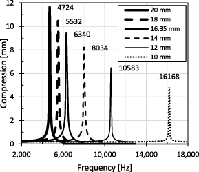
Standard image High-resolution imageFigure 10 compares the first mode harmonic simulation displacement response for 10, 12, 14, 16.35, 18, and 20 mm silicone rubber cord length devices at 1 g. Beyond the frequency range of experimental interest, the devices experience high displacement at resonance frequency ( fr). The 20 mm long cord device exhibits a maximum excitation of 11.6 mm at a resonance frequency of 4724 Hz. The resonance frequency increases for shorter cord devices to 5532 Hz for a 18 mm cord and 6340 Hz for a 16.35 mm cord (figure 2(b)). When compared to long cord devices, short cords experience a significantly higher resonance frequency. The 10 mm long device has a resonance frequency of 16,168 Hz. Thus, the silicone-cord length can be considered a mechanism to shift the resonance frequency.
Figure 10. First mode harmonic simulation compression of various piezoelectric-silicone device lengths at 1 g.
Download figure:
Standard image High-resolution image
Consequently, the proposed energy harvesting structure can harvest mechanical energy at maximum displacement, potentially leading to a higher energy yield [43]. On the other hand, the compression of the silicone rubber at resonance frequency exceeds the maximum value of 35% for all cord lengths, potentially leading to mechanical failure of the energy harvesting device [35]. According to the frequency response of the piezoelectric-silicone device in figure 10, the corresponding mechanical damping ratio is derived for the silicone rubber cord based on the half-power frequency response magnitude. With a damping ratio of 0.06 at resonance for all silicone rod lengths, the energy harvesting devices exhibit an elastic frequency response and a quality factor of 8.3 which is within the range for rubber structures [44]. Hence, the mechanical properties of the silicone cord are similar to pure silicone rubber and are not compromised by the piezoelectric tube.
6. Conclusions
Due to the volatile nature of electricity and the limited ability of storing electrical energy, it is challenging to implement changes and improvements to energy efficiency, conversion effectiveness and generator size and weight. However, the proposed piezoelectric-silicone rubber energy harvesting device effectively generates electrical energy from mechanical energy. The performance is primarily determined by the design (shape, size, material selection) and external factors (mechanical excitation amplitude, frequency). When optimising the design, materials with a high Poisson's ratio are favourable while the piezoelectric materials with a high piezoelectric coefficient (i.e. ceramics) are preferred. Other approaches may be possible with piezoelectric polymers. The proposed relative optimisation method compares the length of the silicone-cord to the open circuit voltage. The results show that off-the-shelf FEM models overestimate the device performance and do not accurately reproduce the complexity of the electro-mechanical interaction. Finally, the complexity of the multi-physics energy harvesting device with material properties spreading across several orders of magnitude requires a careful experimental optimisation due to the material mix and secondary physical effects. Future experimental work will target an embedded piezoelectric tube structure for compression and elongation energy harvesting while numerical work will target the development of a custom-built FEM solver, addressing all underlying physical principles of the device. Despite the successful proof-of-concept of a highly flexible energy harvesting device, the idea of harvesting the world's mechanical energy with piezoelectric materials is still a significant challenge.
Acknowledgments
This research received funding from the Royal Academy of Engineering (RAEng) under the Research Fellowship Program Number RF\201819\18\202.