

Abstract
A design procedure for the synthesis of active camber morphing wing devices is proposed. A topology optimization initially defines the internal structure that is further enhanced by structural size and shape optimizations, and these optimizations are based on the distributed compliance concept. The size optimization enables the adaption of the topology solution to other materials and geometries while refining the topology solution to improve the shape quality of the skin deformation. Then, the structural shape optimization enables the reduction of the stress peaks inside the compliant structure and the finalization of the details to obtain a solution that is closer to the manufacturing process stage. The proposed methodology is used in the design of an adaptive droop nose to be installed on a reference regional aircraft, and two different design applications are considered. The first application is the validation of the procedure at the full–scale level using a superelastic material for the internal structure. The second application is the design of a corresponding 3D–printed prototype, in which both geometry and material changes are considered, for experimental validation. The results show satisfactory shape quality and the achievement of structural feasibility. The experimental functional test of the scaled prototype demonstrates the effectiveness of the adopted morphing solution.
Export citation and abstract BibTeX RIS

Original content from this work may be used under the terms of the Creative Commons Attribution 4.0 license. Any further distribution of this work must maintain attribution to the author(s) and the title of the work, journal citation and DOI.
1. Introduction
Morphing is a solution that can be used to improve the global performances of modern aircraft by enabling the achievement of higher aerodynamic efficiency by adapting the wing shape during the mission. However, the potential benefits of morphing, which have been estimated by numerical simulations, are often in conflict with technological aspects that are related to its implementation on real aircraft due to undesirable weight penalty, manufacturing and installation issues and underestimated actuation power, which can reduce the expected advantages of morphing. Therefore, the design process should lead to solutions that anticipate manufacturing requirements to avoid focusing on ineffective solutions and to try to increase the technology readiness level (TRL) of morphing devices.
One of the most promising morphing concepts is active camber morphing, the objective of which is the variation of the airfoil camber to increase the aerodynamic performance, especially in the take–off and landing phases [1]. Different experimental solutions, which are based on a flexible skin that is coupled to a rigid mechanism that has rigid levers and kinematic joints, have been proposed and evaluated over the years, beginning at Boeing and NASA [2–6].
Regarding the trailing–edge, a finger–like concept that was based on ribs that were composed of several plates linked by revolute joints and connected to the skin using slide joints, was proposed in Europe by Monner [7] in the framework of the ADIF project. Monner also studied a morphing solution for replacing the conventional droop nose device installed on the Airbus [8] by the adoption of optimization techniques. The seamless and gapless design of the high–lift device aimed at reducing the acoustic emissions and drag and at introducing laminar wing technology.
The same objectives have been pursued in many other EU projects, such as SADE [9] and SARISTU [10], which dealt with the integration of typical leading–edge de–icing, erosion, and bird strike protections. Moreover, the participants in the SARISTU project included the Department of Aerospace Science and Technology at the Politecnico di Milano (PoliMi), which was involved in the optimal definition of the morphing shapes to be achieved by the leading–edge, trailing–edge and winglet devices [11].
Solutions based on a flexible skin coupled to a rigid mechanism suffer from the typical issues of mechanical components, such as wear, backlash, and weight, and all the disadvantages related to the many assembled parts [12, 13]. Compliant structures are an alternative to the rigid kinematics approach due to their ability to transform an actuation input into a desired motion or shape change by exploiting the elastic deformation inside the entire structure [14, 15]. In contrast to rigid mechanisms, compliant structures are constructed as single pieces without joints; hence, they exhibit longer fatigue life and higher reliability. Compliant structures do not require assembly and are not subjected to friction or backlash [16]. Moreover, compliant structures are easier to manufacture, which can lead to time and cost savings [17].
In addition to the advantages that are discussed above, compliant structures are suitable for use in the aeronautical field, since they can combine kinematic and load–bearing properties. Indeed, the absence of hinges of any kind, flexible or not, reduces the high stress concentration and enables the realization of seamless and gapless wing devices. Conventional high–lift systems or control surfaces can be replaced by compliant structures to optimize aircraft performances without the drawbacks of mechanical systems. The first experimental application of this concept was proposed by FlexSys Inc. [18], which, in collaboration with Air Force Research Laboratory and NASA, has successfully flight–tested the FlexFoilTM Adaptive Compliant Trailing Edge (ACTE) [19], which was installed on a Gulfstream III aircraft, thereby demonstrating its structural feasibility and aerodynamic efficiency improvement.
The design of devices of this kind requires dedicated synthesis procedures [20]. Kota and Lu have developed a topology optimization algorithm for the definition of the compliant structure, which is followed by a local optimization step for increasing the accuracy of the sizing and improving the solution [21].
Similarly, in the last ten years, PoliMi developed a two–level optimization procedure that is based on the genetic algorithm and is used for the topology optimization of compliant structures [22]. The participation of PoliMi in several projects has provided the authors an important background in the design of structures of this kind for morphing applications. In the Novemor (NOvel Air VEhicle Configurations: From Fluttering Wings to MORphing Flight) project, both full–scale wing devices [23, 24] and corresponding wind tunnel scaled models [25] were developed for the study of leading- and trailing–edge morphing solutions. After the design of the full–scale morphing devices, the design process had to be repeated for the scaled model because the geometry and the stiffness distribution do not follow the same scaling law. Therefore, an additional topology solution was generated, which achieved the desired behaviour in terms of the external shape but considered a different material. Moreover, manufacturing requirements were missing from the optimization process, along with detailed numerical models. To overcome these limitations, suitable optimization tools have been implemented to improve the quality of the results [26].
In this paper, an optimization procedure is proposed for the design of leading- and trailing–edge morphing devices. The starting point for the procedure is the definition of the internal compliant structure, which is obtained via topology optimization. Size and shape optimizations are linked to the two–level optimization procedure, as described above. They combines different design capabilities and takes into account additional constraints, not considered in the first two levels, such as the material, geometry and manufacturing requirements. The size optimization is used as local optimization to refine the structural configuration from the topology optimization. This procedure enables the material to be changed after the definition of the topology solution. Moreover, this procedure enables the use of the same topology for the design of a device with a different geometry, which can be used for experimental validations and wind tunnel tests. Then, the shape optimization reduces the local stress concentrations inside the compliant structure, and a detailed finite element model (FEM) is adopted, which can be converted into a corresponding CAD model that is ready to be manufactured.
This methodology is applied in the EU–funded Clean Sky 2 REG-IADP AG2 project, where a reference regional aircraft equipped with different morphing devices, such as a droop nose, a flap and a winglet, is considered. The contribution of PoliMi is in the design of the morphing droop nose [27], which offers greater advantages from the aerodynamic perspective [28], and overcomes the difficulties in the installation of conventional high–lift devices on regional aircraft. The droop nose is a suitable test case for the assessment of the entire optimization procedure due to the high droop nose deflection that is required by the project, which may produce high stress levels inside the compliant structures. At the full–scale level, superelastic material is adopted in place of the material that is used during the design of the initial topology solution, and this application confirms the capability of the material to change. The whole optimization process is validated through the design, manufacture and testing of a 3D–printed scaled prototype that is made of plastic material, starting from the same topology that was conceived at the full–scale level.
The remainder of this paper is organized as follows. Section 2 presents the whole approach for the design of the compliant adaptive solution. Section 3 describes the reference aircraft and the droop nose that are used as the technology platform for the validation of the methodology. After that, it reports the results that are obtained from the application of the entire procedure to the numerical model of the full–scale device. Section 4 describes the design and the experiment of a half–scale prototype, which further demonstrate the effectiveness of the procedure. Finally, the conclusions are presented in section 5.
2. Design optimization procedure
The optimization procedure consists of four design levels. The topology synthesis is divided in two sequential sub–problems: first determining the optimal morphing shape according to the aerodynamic performance requirements and then using it as the target shape in the design of an internal structure that can deform an external skin into the optimal morphing shape [22]. These two levels are described in Sections 2.1 and 2.2.
The following two levels begin from the results of the topology optimization and consist of a size optimization followed by a structural shape optimization. The size optimization, which is described in section 2.3, refines the topology solution while also considering design changes. The last level, discussed in section 2.4, addresses the problem of the transition to the CAD model of the final compliant structure, and the structural shape optimization is conducted with the objective of minimizing the local stresses. These two levels are based on models of higher fidelity than those used during the topology optimization in the previous levels.
Size optimization works based on the medium–fidelity models that are automatically generated at each optimization step, as described in section 2.3.2. Structural shape optimization works based on high–fidelity models, can consider structural details that are not included in the models that are used in the previous levels, and enables the solution to get close to the level of detail requested for manufacturing. Both levels are developed to extend the field of application of the topology solution and to enhance its performance. After the topology solution has been defined, the levels correspond to the preliminary and advanced designs, respectively, of the compliant structure. Regardless of the material that is used in the topology design, these levels can consider every kind of material, with linear or non-linear constitutive laws. It is possible to replace the materials of both the skin and the internal structure even if the topology has already been defined. Several types of materials can be utilized, which include isotropic, composite, superelastic materials. These levels determine the structural size and shape variables that satisfy both the kinematic and structural requirements, along with changes in the materials and geometric properties. Indeed, one of the main advantages of this approach is the possibility of freezing the topology solution and adapting it to design changes, without the need to return to the beginning of the design process. A solution that is almost ready for manufacturing process and experimental testing is obtained. All these advantages are due to the combined use of a numerical computing environment and a finite element analysis software. The presented approach is highly general, and various implementation techniques may be used. Detailed descriptions of these features are provided in the reference for the external solver Abaqus [29], which is selected for its powerful capabilities in material modelling and non-linear analyses.
2.1. Morphing shape optimization
The optimal morphing shape is defined under aerodynamic shape optimization embedding structural constraints that are related to the morphing skin. The optimization problem definition includes the maximization or minimization of an aerodynamic index, subject to a set of both aerodynamic and structural constraints. On the one hand, the aerodynamic objective functions can consider the global efficiency or the drag coefficient to reduce the aircraft fuel consumption, maximize the lift coefficient in high–lift conditions, and minimize the root bending moment during the flight. Various objective functions can be combined by a multi–objective shape optimization to define a Pareto–optimal shape. Otherwise, more than one optimal morphing shape can be produced for the same wing by different single–objective optimizations to improve the aircraft performances over a wide range of flight conditions. On the other hand, aerodynamic constraints are introduced, for example, to guarantee the trim condition when the wing shape changes due to the morphing, while structural constraints ensure the feasibility of the shape solution from the perspective of the skin structure. This aspect is highly relevant, since the skin deformation plays an important role in the whole morphing solution. Therefore, taking into account its structural behaviour from the beginning facilitates the identification of feasible structural solutions at the later stage.
Shape optimization requires a suitable geometry parameterization to introduce shape changes at each optimization step. The adopted approach consists of an in–house implementation of the class shape transformation (CST) technique, which is based on the method proposed by Kulfan in [30] and is dedicated to the representation of wing surfaces equipped with morphing leading and trailing edges. This technique can compute the strain inside the skin due to the morphing shape modification. The strain is estimated as an analytic function of the curvature variation; hence, only geometric information is considered and it is not necessary to call a finite element solver [31]. An example of morphing droop nose shape, obtained under skin structural constraint, is shown in figure 1. It was computed starting from the parametrically identified wing shape of the reference regional aircraft introduced in section 1.
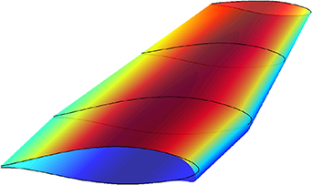
Figure 1. Parameterized wing geometry and example of morphing droop nose deflection under structural constraints on the skin.
Download figure:
Standard image High-resolution image2.2. Topology optimization
Once the optimal morphing shape has been defined, a suitable topology solution for the internal wing structure is required for realizing the desired shape change. The procedure that is adopted in this work leads to the synthesis of compliant structures that are specified systems, which differ from compliant mechanisms. These structures can satisfy conflicting requirements on the deformability, load–carrying capability and low weight to optimize both kinematic and structural objectives. The design of the morphing wing, which is based on compliant structures, consists of the definition of a structure that can transfer the deformation work from an input actuation point to the output points along the skin to deform it and to match the optimal shape or multiple optimal shapes that have been provided by the above shape optimization process. This is the kinematic requirement. Structural requirements are also needed to ensure the realization of the undeformed or the deformed shape under the external loads. In the design of aeronautical structures, several load conditions and flight conditions must be considered. For all these reasons, the topology optimization is based on a multi–objective design problem, which is described in [25], that is efficiently incorporated into an elitist non–dominated sorting genetic algorithm (NSGA–II) [32]. The result of the topology optimization is a Pareto front where the design point can be selected by considering various aspects that are not included in the optimization problem formulation. Since this algorithm is applied to the design of a morphing leading or trailing edge, two main kinds of objective functions are typically considered. The first kind is the structural objective, which tries to minimize the strain energy (SE) of the system in a problem where the input point is fixed, and the external aerodynamic loads are produced by the wing, when it is undeformed and not actuated. The second objective is the kinematic objective, which tries to minimize the least–square error (LSE) between the deformed shape and the optimal morphing shape under the input actuation load and the external aerodynamic loads.
Topology optimization requires a design parameterization of the stiffness tensor to introduce the structural changes inside the design domain at each optimization step. The approach that is adopted in this work is based on the load path representation method, which is described in [22]. Load paths are sequences of beam elements that connect the input actuation point, compliant structure constraints and the output points along the skin by passing through internal points. This representation enables the description of various structural configurations by turning on or off different load paths, varying the cross–sectional beam size, and moving the internal points within the design domain. In the genetic algorithm, individuals are composed of mixed–type design variables, as defined in [22]: the binary path existence variable (Top), the path sequence (Seq), the internal point coordinates (InterCoord), the cross–sectional beam sizes (Dim), the active output point destinations (Out) and the structure boundary sizes (hSkin). The representation of the optimization variables adopted by the genetic algorithm is reported in figure 2, where a demonstrative 2D model of compliant structure is shown.

Figure 2. Optimization variables.
Download figure:
Standard image High-resolution imageIn the genetic algorithm, the objective functions are computed by an in–house non-linear finite element solver that transforms each set of load paths and each part of the skin into a sequence of finite volume beams. The generation of models of this kind, which have few degrees of freedom and are completely embedded into the genetic algorithm, renders the topology optimization highly efficient. This optimization can produce different design points and can be used to perform parametric studies in a short time. These are highly important features, since the topology optimization is conducted in a conceptual design phase in which many solutions are examined prior to the identification of the optimal solution. Indeed, many considerations, which are not necessary included in the optimization, contribute to this choice, such as the weight evaluation. Moreover, the genetic algorithm thoroughly explores the entire design space, and since finding the exact optimum is not the objective of the global optimization process, the use of reduced–order models is justified at this stage. However, low–fidelity models suffer from various limitations, and additional design steps must be conducted to develop the compliant structure solution up to the manufacture of a prototype.
2.3. Size optimization
The size optimization is used to improve the compliant structure and to adapt the topology solution to the structural configuration. The starting point is the optimal topology solution that is obtained via the genetic algorithm. A search is conducted around the optimum that has been identified via global topology optimization. This process can accelerate the convergence to the optimum in the region that corresponds to the design point that is selected on the Pareto–front. A three–dimensional model replaces the two–dimensional model that is embedded in the NSGA–II, while the load path–related quantities are no longer design variables. The new model consists of beam elements that are used for the compliant rib that is located in the middle of the skin, which is modelled with plate elements, whose spanwise length is equal to the wing rib pitch.
2.3.1. Optimization problem definition.
The developed size optimization is mathematically formulated as follows:

where LSE is the least–square error between the deformed shape, which is computed in the new finite element model, and the target shape, which is computed in section 2.1, when the mechanism is actuated. The LSE is evaluated at control points that have been placed at the same arc–length along the skin [22]. The first constraint is on the strain energy (SE) of the model under the aerodynamic loads of one or more design conditions, such as the dive speed, while keeping the mechanism fixed. This function, which must be restricted below a threshold defined by the design requirements, represents an index of the deformability of the morphing structure when the device is not actuated. This threshold guarantees that the compliant structure can withstand the aerodynamic loads without affecting the wing performances. The second constraint is the structural limitation that is related to the stress inside the mechanism when it is actuated.  is the maximum stress that is computed in the compliant rib by the finite element analysis, while
  is its admissible value. A similar constraint for the skin is optional since the airfoil curvature variation and the strains inside the skin are related, which is considered during the aerodynamic shape optimization.
The design variables of the problem are a sub–set of the genetic coordinates, which have already been discussed in section 2.2 and shown in figure 2. They are suitably bounded between lower and upper limits and they are listed as follows:
- the cross sectional size Dimi of the beam segments inside the compliant rib;
- the thickness hSkinj of each skin region along the arc–length;
- the coordinates interCoordk of the internal points.
The optimization algorithm is a sequential quadratic programming (SQP) method, and the Hessian of the Lagrangian function is approximated using a quasi–Newton updating method at each major iteration. The corresponding QP sub–problem is generated and solved, which yields the search direction of a line search procedure [33].
It is possible to interchange the LSE objective function and the stress constraint to minimize the maximum stress inside the compliant structure while limiting the LSE below a selected value. The alternating application of the two problems can yield major improvements in the solution.
2.3.2. Modelling and gradient computation.
The objective and the constraint functions of the size optimization are computed by finite element analyses that are conducted by Abaqus. Dedicated scripts in the Python language were developed to automate the generation of the model, run the simulations and make the optimization as efficient as possible. Illustrative examples of the generated models, in the cases of leading- and trailing–edge devices, are shown in figure 3.

Figure 3. Medium–fidelity models that are used by the size optimization.
Download figure:
Standard image High-resolution imageAccording to the optimization problem definition, and since large deformations are expected inside the compliant structures, two different kind of static non-linear analyses can be conducted:
- (a)analysis of the model that corresponds to the kinematic requirement and to the LSE computation when the compliant structure is actuated and the skin is subjected to the aerodynamic loads that are related to the morphing configuration; and
- (b)analysis of the model that corresponds to the structural requirement and to the SE computation when the actuation point is kept fixed and the skin is subjected to the aerodynamic loads that are related to all flight conditions considered in the structural design.
Both analyses are conducted to compute the objective and constraint functions at each optimization step and to calculate their gradients with respect to the optimization variables. A suitable search direction is determined for locating the point that is related to the next optimization step. Moreover, the optimization variables include the size variables of the skin and the rib, and they may also include the positions of the internal points. If only size variables are considered, a simplified version of the optimization problem is utilized for several reasons. The first reason is related to the search space being smaller and easier to approximate. This condition implies a shorter computation time of the whole optimization process. The other reasons are related to the model generation, which can be accelerated by observing that the geometry is kept fixed while only the size quantities change. Therefore, the model can be generated once, and the optimization variables simply change the properties of the finite elements that are included in the model. Moreover, if only element properties change during the optimization, a sensitivity analysis can be conducted to evaluate the objective and constraint gradients with respect to the optimization variables. The derivatives of the model stiffness matrix with respect to the variables can be analytically computed from the stiffness matrix of each element and used to efficiently evaluate the objective and constraint gradients [34]. Otherwise, if the coordinates of the internal points are between the optimization variables, the model must be generated at each iteration; hence, the problem is much more complex, and the algorithm conducts additional analyses to evaluate the gradients by finite differences. The number of additional analyses is equal to the total number of variables, which incurs a higher computational cost. Whether it is worth implementing the more expensive approach will be considered in the discussion of the results.
The model generation is performed at the beginning of the process and at each optimization step if the variables include the internal point coordinates. Therefore, an interface for automatically generating the mesh and conducting the analyses is written in Python. The mesh consists of three–dimensional beam linear elements, which are used for the rib and the stringers, and 4–node quadrilateral shell elements with large–strain formulations, which are used for the skin. While the optimization algorithm determines the values to be assigned to the variables, many parameters and data remain constant throughout the process and must be externally supplied. The rib geometry is defined by a connectivity matrix that describes the topology of the compliant structure, while the skin geometry is defined by the external wing shape. The rib pitch, which is denoted as prib, and the rib thickness, which is denoted as wrib, define the spanwise lengths of the skin and rib, respectively. Stiffeners that are oriented in the spanwise direction are located where the rib is connected to the skin, and their size must be specified in terms of the cross-sectional dimensions. Material properties of the rib, skin and stiffeners are also defined as external parameters. The boundary conditions depend on the kind of analysis that is performed. In the first kind that is described above, the actuation is introduced in terms of enforced motion and a predefined kinematic chain or, alternatively, by specifying the orientation and magnitude of the actuation force. The aerodynamic pressure distribution, together with the dynamic pressure that corresponds to the considered flight conditions, is applied to the skin. Suitable constraints, which depend on the kind of the analysis that is performed, are applied to the points where the load paths and the skin are connected to the structural wing–box.
2.4. Structural shape optimization
At the end of the previous step, an optimized model is obtained that well satisfies the deformed shape quality requirement and does not violate the structural constraints. However, another step is needed to prepare for the executive design that precedes the manufacturing process. Indeed, the compliant rib model that has been addressed until now consists of beam elements. These elements guarantee a sufficiently accurate estimate of the stress far enough from the element extremities, but they lack reliability in the connection regions. Moreover, in these zones, the manufacturing details of the fillets are missing, since they cannot be regarded as simple intersections at single points. These premises constitute the reason behind the need to conduct the optimization analysis that is described in the following.
The analysis focuses on the internal compliant rib. First, starting from the beam model of the optimal solution, a CAD model of the compliant mechanism is created. This model inherits the internal point positions and the load-path cross-sectional sizes from the beam elements, while suitable fillets are used to link the paths at their intersections. Later, starting from the CAD model, a plane sketch is generated, which is finely meshed in Abaqus with two–dimensional, 4–node bilinear, plane stress solid elements.
The optimization process is facilitated by the tool Tosca.shape. The proposed shape optimization consists of identifying the optimal positions of the nodes for the minimization of the maximal principal stress in the structure under specified constraints. By modifying the component surface, it is possible to refine the optimal solution by reducing the local stresses, thereby increasing the fatigue life and the reliability of the compliant device. The setup of the shape optimization problem does not require model parameterization, since the design area is defined by specifying groups of nodes. Regarding the constraints, the volume is not allowed to change. Another constraint, which is necessary for properly guiding the analysis, is on the minimum member size and belongs to the family of geometric restrictions; the minimum distance between two geometric edges cannot be less than the selected minimum thickness.
The design region, which is modified by the shape optimization, includes the surface nodes of the whole model or of a subset of them, and the internal nodes are allowed to move. A dedicated mesh smoothing technique is embedded in the process to avoid mesh distortions and to guarantee a high–quality mesh at each optimization step. The internal node displacements are not design variables, but they are moved as a consequence of the outer node displacements, with the sole objective of avoiding the creation of overly distorted elements. An example of nodes that belong to the design area and are related to the connection between 3 load paths, along with the corresponding fillets, is presented in figure 4.
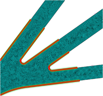
Figure 4. Shape optimization: An example of the design area inside a compliant structure.
Download figure:
Standard image High-resolution imageThe shape optimization is based on non-linear static analyses that are performed on models of this kind. The objective and constraint function evaluation consist of imposing displacements and in–plane rotations at the points where the rib is attached to the skin while applying the enforcing motion (or the force) due to the actuation. The strategy is to optimize the contour shape of the rib so that the produced skin deformation is the same as that obtained on the beam model. Therefore, the displacement history to be applied along the contour is extracted from the beam–model solution, which was already obtained by the size optimization, while the actuation modelling is the same.
The major issue that is encountered in performing this kind of analysis comes from the nature of the model, since there are no simple lines and points but a mesh of solid elements. To correctly apply the boundary conditions, the contour of the mesh at the ends of the load paths is correctly modelled to simulate the effect of the link on the remainder of the structure. Different kind of rigid and flexible kinematic coupling constraints are introduced into the model to connect the constraint, input actuation and active output points.
Another approach involves both the mechanism and the skin. In this case, the modelling approach utilizes 3D solid elements. The advantage of this approach lies in the concurrent availability of the complete refined finite element model. This model can be used for detailed numerical verification at the end of the optimization process. Moreover, due to the presence of the skin, the imposed displacements are no longer needed at the boundaries. Both approaches to the problem will be discussed in Sections 3.4 and 4.2 respectively, and they will be compared. A final verification is conducted to determine whether the geometry modifications that are induced by the structural shape optimization do not significantly alter the shape quality of the achieved skin deformation.
3. Adaptive droop nose application
In the framework of the EU–funded Clean Sky 2 REG–IADP AG2 project, one of the developed morphing devices is an active compliant droop nose that can guarantee high–lift requirements in combination with a Natural Laminar Flow (NLF) wing. The first design phase consisted of the definition of the optimal external shape that satisfies the aerodynamic requirements of the NLF wing. The reference aircraft that is considered in the project holds 90 passengers and is a twin–prop Regional Aircraft whose reference NLF wing has been optimized by ONERA.
The design of the compliant droop nose was based on the two–level approach that is described in section 2.
The external morphing geometry was defined by the aerodynamic shape optimization of section 2.1, while the results in terms of the aerodynamic performances and structural behaviour of the skin were presented in [28]. Figure 5 shows the deployed morphing droop nose that is installed on the NLF wing.

Figure 5. Reference wing that is equipped with the adaptive droop nose.
Download figure:
Standard image High-resolution imageAfter the morphing droop nose was defined from the perspectives of the aerodynamics and external shape, it was used to design the internal solution in terms of the optimal compliant structure. The obtained topology solution represents the starting point for the application of the size and shape optimizations.
The main goal of the droop nose design at full–scale level is to define a virtual prototype that is suitable for performing detailed stress analyses and for validating the morphing device functionality. Therefore, size and structural shape optimization are applied to complete all the design phases up to the definition of a structural and mechanical solution that takes into account all the details of an experimental prototype, without manufacturing it.
The initial design of the skin is already discussed in [27] and it is based on the use of a glass–fibre fabric composite material, whose parameters are reported in table 1.
Table 1. Fibreglass fabric mechanical properties for the skin.
| Parameter | Value |
|---|---|
| E11 | 25 GPa |
| E22 | 25 GPa |
| ν | 0.20 |
| G12 | 4 GPa |
| G13 | 4 GPa |
| G23 | 4 GPa |
Even though the droop nose device extends along almost the entire wingspan, the focus of this work is the detailed design, from the perspectives of both the internal shape and the structure, of a limited spanwise width of the structure. As previously explained in section 2.3, the considered length is equal to the rib spacing inside the wing leading edge. The rib pitch parameter prib is equal to 130 mm, and it is used as the span–wise length of the skin, while the rib thickness wrib is selected to be 35 mm. This work presents a suitable solution for the inner wing region in terms of detailed CAD and FEM models. The design procedure can be applied to different wing sections along the span to finalize the design of the whole device, but this aspect is outside the scope of the presented work. The input actuation inside the complete device is introduced through a rotation of 70 deg of a shaft that is connected to the compliant ribs by a rigid kinematic chain. The droop nose device is connected to the wing–box through the skin, which is clamped to the front spar on both the upper and lower surfaces. Since the chord of the considered wing section is 2.911 m, and the front spar is located at 16% of the chord, the chord extension of the device is 467 mm.
The design steps are reported in the following. At the beginning, the topology optimization results are presented. Then the optimization results on medium- and high–fidelity models, the verification of the solution at different aircraft operating temperatures, and a final validation are reported.
3.1. Topology optimization
The topology synthesis of the compliant ribs was performed via the multi–objective genetic algorithm that is described in section 2.2. This design phase has been already presented in [27]. Three objective functions were considered:
- (a)Structural requirement: minimizing the SE to preserve the NLF wing shape when the morphing mechanism is kept fixed under the aerodynamic loads that correspond to the dive speed at sea level (Mach = 0.48).
- (b)Kinematic requirement: minimizing the LSE between the target and deformed LE shapes when the droop nose is deployed under the external aerodynamic loads that correspond to the landing flight conditions at sea level (Mach = 0.197 and α = 10°).
- (c)Minimizing the maximum value of the strain in the mechanism when it is deployed under the same conditions of the kinematic requirement.
The aerodynamic loads that correspond to the kinematic requirement are presented in figure 6.
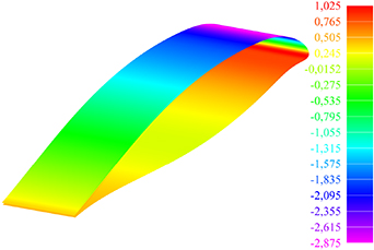
Figure 6. Optimal morphing shape and the corresponding aerodynamic loads for the kinematic requirement.
Download figure:
Standard image High-resolution imageThe topology solution was selected on the Pareto front as a satisfactory compromise between conflicting kinematic, structural and strain requirements. Additional criteria were considered in the selection, such as the manufacturing readiness of the topology solution. The solution is shown in figure 7 and it represents the optimal compliant structural configuration for all the applications that are discussed hereafter.
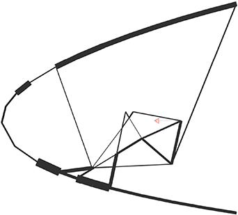
Figure 7. Topology solution.
Download figure:
Standard image High-resolution imageThe corresponding model is made of beam elements for both the skin and the mechanism. To account for the effect of the skin stiffness due to its spanwise extension, an equivalent size is assigned to each beam to represent the skin in the 2D beam model. When the compliant structure is actuated, the results are characterized by an LSE value of 6.5 mm.
A medium–fidelity model of the initial solution is then generated in Abaqus, which features a beam element rib that is coupled with a shell element skin, as described in section 2.3.2. The analysis on this model shows an LSE value of 10.2 mm, which is due to the model that probably captures aspects not included in the volume beam model embedded into the genetic algorithm. This solution is shown in figure 8.
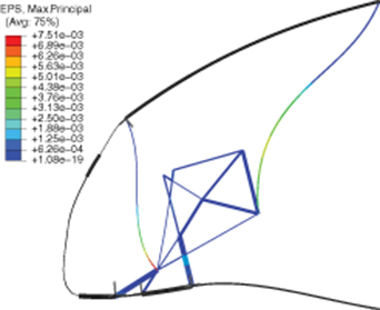
Figure 8. Strains and the deformed shape of the initial topology solution that was computed on the medium–fidelity model.
Download figure:
Standard image High-resolution imageThese results display a maximum strain of 0.76% inside the mechanism. The choice to accept such a high level of strain was dictated by the need to realize the 16–degree droop angle to satisfy the design requirements. However, this strain value is not allowable for conventional linear elastic isotropic materials that are adopted in the aeronautical field. This fact suggests the need for materials that can provide high recoverable strains, such as Nitinol, which exhibits superelastic behaviour. By using this material, the first application that is discussed tries to convert the above solution into a structurally feasible solution.
Size and structural shape optimizations, which are presented in section 2.3 and 2.4, are applied to the preliminary and advanced design of the adaptive droop nose, starting from the initial topology solution that was described. When passing from the low–fidelity finite-volume beam model to the medium–fidelity beam and plate model, the new material of the structure is introduced. The design performed at full–scale level considers Nitinol as the material to be assigned to the internal compliant rib.
3.2. Superelastic material
Superelasticity is one of the peculiar properties of shape memory alloys such as Nitinol. In contrast to the shape memory effect, superelasticity can be exploited passively without the need of thermal loads. Indeed, due to a mechanical–stress–induced transformation, at relatively high temperatures, the recovery of very large strains upon unloading is enabled, without permanent deformations. The use of superelastic materials applied to morphing aircraft was already discussed in [35]. To understand the behaviour of shape memory alloys, it is essential to consider the four characteristic transition temperatures, namely, Mf, Ms, As and Af, which are listed in ascending order. M stands for martensite and A for austenite. Subscripts f and s specify the finish and start temperatures of the transformation processes. The martensitic phase is stable at temperatures below Mf. The austenitic phase is stable at temperatures higher than Af. For temperatures between As and Ms, both phases are simultaneously present.
The superelastic effect is due to the dependence of the transition temperatures on the stress level. The superelastic effect occurs when, starting from austenite at a temperature above Af that is kept constant, a load is applied up to a critical stress value, which induces martensite transformation. Continuing to increase the stress level, the transformation finishes, and the elastic loading of martensite begins. If the plastic limit is not reached, the described transformation is reversible upon unloading and will return to a zero–strain condition. Therefore, an initial austenitic phase is a necessary condition for the occurrence of superelasticity. However, if the temperature is higher than a temperature Md, the material will show an elastic–plastic behaviour. Indeed, if the critical stress for slipping at a temperature is lower than the critical stress for inducing martensite at the same temperature, the superelastic behaviour does not occur, and irreversible strains remain [36].
In the aerospace field, the superelastic effect is less common than the shape memory effect; however, various applications can be found, as in [37], where Nitinol is used in the manufacturing of a compliant mechanism. Superelasticity–based applications exploit the possibility of recovering large deformations and the existence of the transformation stress plateau, which guarantees near–constant stress over large strain intervals [38].
The complexity of shape memory alloys renders their modelling highly difficult. A user material routine, which is based on the model that was proposed by Auricchio and Taylor [38], was developed by Hibbitt, Karlsson & Sorensen [39]. This constitutive model is implemented in Abaqus as a UMAT user material, and it is suitable for simulating the superelastic behaviour. The material data that are required for establishing the numerical model characterize the start and the end of the phase transformation during loading, unloading and reverse loading. The σ −  curve, along with the significant parameters, is shown in figure 9, while table 2 lists the parameters that are required by the material routine for superelastic–only use and the values that are selected in this work.

Figure 9. Typical superelastic stress–strain curve.
Download figure:
Standard image High-resolution imageTable 2. Nitinol mechanical properties for the compliant rib.
| Parameter | Definition | Value |
|---|---|---|
| EA | Austenite Young's modulus | 72 GPa |
| νA | Austenite Poisson's ratio | 0.33 |
| EM | Martensite Young's modulus | 30 GPa |
| νm | Martensite Poisson's ratio | 0.33 |
| L |
Transformation strain | 0.05 |
 |
δσ/δT loading | 7 MPa/K |
 |
Start of transformation loading | 441 MPa |
 |
End of transformation loading | 511 MPa |
| T0 | Reference temperature | 293 K |
 |
δσ/δT unloading | 7 MPa/K |
 |
Start of transformation unloading | 301 MPa |
 |
End of transformation unloading | 231 MPa |
 |
Start of transformation stress | 441 MPa |
| in compression |
The parameter values, such as Young's modulus, Poisson's ratio and the Clausius–Clapeyron coefficients, are obtained from Qidwai and Lagoudas [40], while the other values are obtained by setting the transformation temperatures to exploit the superelastic behaviour for a range of aeronautical operative temperatures, which are selected between a minimum of  K and a maximum of
  K. This is possible, since transformation temperatures can be widely shifted after manufacturing by applying suitable solution annealing and ageing treatments [41].
According to the objective, the austenite finish temperature must be below the minimum temperature; hence, a value of 260 K is chosen. Moreover, the stress at the end of the martensite transformation is below the critical stress for slipping, which is assumed here to be on the order of 800 MPa, up to the maximum temperature. Therefore, a suitable martensite finish temperature may be 220 K. Figure 10 shows the relationships between the selected transformation temperatures and the stress level. The reference temperature and the minimum and maximum temperatures are highlighted.
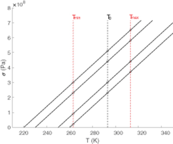
Figure 10. Reference and limit temperatures in the stress–temperature diagram of the considered Nitinol.
Download figure:
Standard image High-resolution imageAll the computations for the design that involves Nitinol are performed at the reference temperature T0 = 293 K. After the design is completed, verification in terms of the deformed shape and the internal stress is conducted using the limit temperatures.
3.3. Size optimization
The medium–fidelity model that is used for the size optimization is defined after all the external parameters, which are described in section 2.3.2, have been provided. Regarding the materials, the Nitinol parameters for the compliant rib are reported in the previous section, while the skin is made of a glass–fibre composite material, whose parameters are reported in table 1. All other parameters, which are related to the geometry, actuation and aerodynamic conditions, have been already discussed at the beginning of section 3.
Initially, a static analysis is performed to evaluate the LSE and the maximum internal stress of the initial solution. Even if the material has been changed, the deformed shape is characterized by an LSE value of 10.2 mm, which is the same value as reported in section 3. The maximum Von Mises stress inside the mechanism is 448 MPa; hence, the initial solution is feasible. Examining the strain, a maximum value of 0.84% is observed, and it is in the range of the transformation strains that can be recovered upon unloading. Such a deformation level, which is not compatible with the behaviour of conventional aeronautical materials, suggests the adoption of a superelastic material for the application that is considered here. The results that are presented in the next sections confirm this choice.
The optimization problem formulation is described in section 2.3. The initial values to be assigned to the optimization variables are derived from the solution that is selected on the Pareto front and computed by genetic algorithm.
Regarding the stress constraint, an admissible stress of 500MPa is considered; this value is immediately below the stress level at the end of the loading plateau. A corresponding constraint for the stress inside the skin is not considered, since it is ensured by the curvature level of the target shape.
The optimization is run, and it converges to an optimal solution in 49 iterations. The evolution of the objective function with the iteration number is shown in figure 11, and a LSE of 1.44 mm is obtained for the optimal solution. The stress levels inside the compliant rib and a comparison between the optimal deformation and the target shape are shown in figure 12.
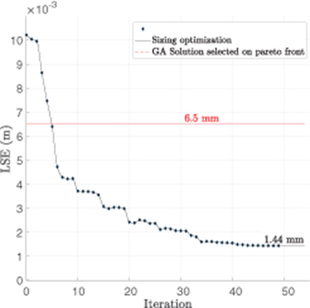
Figure 11. Convergence curve of the size optimization with internal point variables.
Download figure:
Standard image High-resolution image
Figure 12. Full–scale model solution that is computed by the size optimization in terms of Von Mises stress inside the compliant rib and a comparison between the deformed and target shapes.
Download figure:
Standard image High-resolution imageThe starting solution and the optimal solution are compared in terms of the optimization variables in figure 13, where the thickness values are magnified by a factor 3 for a clearer visualization.

Figure 13. Thicknesses of the initial and optimal solutions.
Download figure:
Standard image High-resolution imageThe results show a significant LSE reduction from 10.2 mm to 1.44 mm. This reduction is associated with a rearrangement of the thickness distribution inside the compliant mechanism and the skin. The maximum stress in the internal mechanism is 462 MPa and the corresponding maximum strain is 0.018, which is still in the range of the recoverable strains. These results demonstrate that:
- Compliant structures are compatible with the use of superelastic materials. When large strains are expected, the stress plateau enables the limitation of the stress values inside the structure;
- A large range of deformations can be exploited to achieve a meaningful improvement of the existing design in terms of the kinematic objective, which is more than conventional elastic materials can provide.
An optimization, in which the positions of the internal points are not optimization variables, has been performed. The LSE optimization history is shown in figure 14.

Figure 14. Convergence curve of the size optimization without internal point variables.
Download figure:
Standard image High-resolution imageThe optimization analysis rapidly converges; however, the minimum LSE value is equal to 4.18 mm, which is larger than the previously obtained optimal value. Hence, adapting an existing topology solution to a different material requires the possibility of slightly moving the internal points of the mechanism; otherwise, a sufficient improvement of the objective cannot be achieved.
3.3.1. Operating temperatures.
The presented results have emphasized the advantages of adopting the superelastic material in terms of both shape quality and structural feasibility. The superelastic behaviour depends on the transition temperatures, which are related to the temperature of the considered application. Previous results utilized the design temperature of T0 = 293 K, but the parameters are selected to cover a wide range of possible application temperatures. In this section, the optimal solution that is provided by the size optimization is verified at the limit temperatures of  K and
K and  K. The analyses are performed on the same medium–fidelity model, and the enforcing motion that is introduced by the actuation is extracted from the results that were obtained at the design temperature.
The results of these analyses in terms of the deformed shape are shown in figure 15, while the LSE values at the different temperatures are compared in table 3. The magnitude of the actuation force that is required for accomplishing the desired motion in each case is also reported.
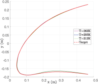
Figure 15. Comparison between the target and deformed shapes at different temperatures.
Download figure:
Standard image High-resolution imageTable 3. Optimal solution results at different temperatures.
| Temperature (K) | LSE (mm) | Actuation Force (N) |
|---|---|---|
| 263 | 1.77 | 422 |
| 293 | 1.44 | 470 |
| 313 | 1.57 | 498 |
As expected, the smaller LSE is obtained at the design temperature, but the differences in the off–design conditions are negligible. The differences in the actuation forces are due to the stress level inside the compliant rib, which depends on the transformation starting point, which changes if the operative temperature changes. The maximum principal stress–strain relationships in the most critical point of the structure are compared in figure 16, where the unloading of the structure and the recovery of the transformation strains are also reported. The lower the temperature is, the lower the plateau stress and the higher the transformation strain are.
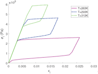
Figure 16. Stress–strain superelastic behaviour at different temperatures.
Download figure:
Standard image High-resolution image3.4. Structural shape optimization
Starting from the solution that is provided by the size optimization, a two–dimensional solid model of the compliant rib that is made of Nitinol is generated. The first approach described in section 2.4, which is based on static analysis with the application of enforced displacements at the boundary, is followed, in which the reference temperature is considered. The corresponding results in terms of the deformation are shown in figure 17. In addition to the global deformation, the most stressed regions are highlighted.

Figure 17. Static analysis results on the high–fidelity model and the critical regions that are subjected to the structural shape optimization.
Download figure:
Standard image High-resolution imageThe use of a more refined finite element model enables the local stress concentrations to be captured, which are not considered during the size optimization.The beam model solutions are highly accurate from the kinematic perspective, but they cannot correctly estimate the stress at critical points, such as the extremities and intersections. The aim of the shape optimization is to try to reduce the local stress peaks in the more critical regions of the compliant structure. The shape optimization of section 2.4 is applied to the region that is depicted in figure 17.
Regarding the right–side region, the initial maximum stress is 549 MPa, and the objective function minimizes the maximum principal stress that is evaluated in this region. After eight iterations the maximum stress value is reduced to 525 MPa. The initial and the optimized solutions are compared in figure 18, where an effective stress redistribution can be observed. Moreover, the transformation strains are significantly reduced from a maximum value of 0.042 7 to a maximum value of 0.015 7. The stress–strain relationship for the loading history before and after the optimization process is also reported in figure 18, which shows that the plateau is partially exploited in both cases.
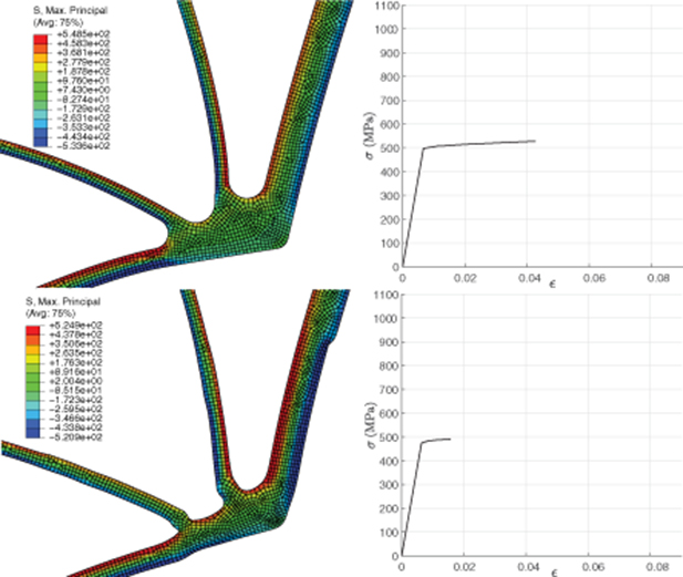
Figure 18. Comparison between the initial (top) and optimal (bottom) solutions that are computed by the shape optimization around the right–side region: stress distribution (left) and stress–strain superelastic behaviour in the most critical point (right).
Download figure:
Standard image High-resolution imageIn the left-side region of figure 17, a similar optimization is carried out. In this case, the finite element model shows an initial stress concentration of up to 1052 MPa, which is much higher than the value that is obtained from the beam model. Shape optimization achieves a substantial stress reduction and proves to be crucial in the definition of a feasible structural configuration; after seven iterations, the maximum stress value is reduced to 541 MPa. The initial and the optimized solutions are compared in figure 19.

Figure 19. Comparison between the initial (top) and optimal (bottom) solutions that are computed by the shape optimization around the left–side region: stress distribution (left) and stress–strain superelastic behaviour in the most critical point (right).
Download figure:
Standard image High-resolution imageThe initial solution is not feasible because the plateau is fully exploited, and the stress limit is exceeded at the end of transformation; hence, permanent deformations remain upon unloading. Otherwise, in the optimal solution, the plateau is partially exploited, and deformations can be recovered. These two behaviours are also compared in figure 19.
3.5. Numerical validation
A numerical assessment is carried out to determine whether the solution that is provided by the structural shape optimization alters the LSE performance beyond a predefined tolerance with respect to the estimate that was obtained via the size optimization. A 3D solid model of the compliant rib, which was derived from the shape optimization result, is generated and coupled with the shell element skin. The motion due to the kinematic chain is applied to the actuation point, and the skin deformation is computed. The deformed and the target shapes are compared in figure 20.
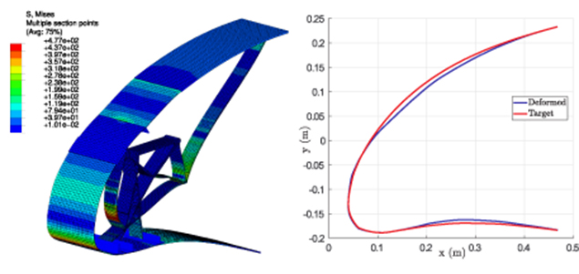
Figure 20. Full–scale model validation on the high–fidelity model in terms of the Von Mises stress and comparison between the deformed and target shapes.
Download figure:
Standard image High-resolution imageThe maximum stress inside the rib is 477 MPa, and the corresponding strain is 0.026; hence, the solution is feasible. Regarding the shape quality requirement, the LSE is 4.4 mm, which is worse than that achieved by the size optimization (1.4 mm). This outcome is mainly due to the presence of all manufacturing details, fillets inside the rib model and connections between compliant rib and skin models, which are not considered in the model that is used by the size optimization. The worsening LSE is only partially due to the application of the structural shape optimization without the skin, thereby enforcing the displacement at the rib boundaries. However, the actual value of LSE is between the values that were obtained by the topology and the size optimizations. Hence, the actual LSE depends on the size optimization results, and it represents an improvement with respect to the LSE value used to select the design point on the Pareto front.
The results presented in this section enable the numerical validation of the overall procedure for expanding the use of previously defined topology by considering other materials. At the same time, this procedure decreases the LSE with respect to the results obtained by the topology optimization and reduces the stress inside the compliant structure. The performance improvement and constraint satisfaction are proven by considering the non-linear material behaviours, such as the superelastic effects, and the manufacturing details, such as the fillets and connections among the internal structure, skin and actuation system, which are not included in the topology optimization models. The complete model that is used during the numerical validation can be directly adopted inside the shape optimization. The 3D solid model of the compliant rib, which is connected to the shell element skin and to the actuation system, can facilitate the improvement of the results in terms of the shape quality, as described in section 2.4. This second approach is selected for the half–scale prototype design that is discussed in section 4.
4. Half–scale prototype design
The optimization procedure that is proposed in this work can be used to apply the specified topology to a droop nose with a different geometric scale and a different material. The typical application of this problem is the scaling process for designing a scaled prototype for experimental validations. The design of scaled models for experimental tests represents a challenging problem, since the scaling law for the stiffness differs from the geometric law and, usually, it is necessary to change both the topology and the material to reproduce the required characteristics. This change requires a complete redesign of the structure. However, the availability of the procedure presented here suggests the possibility of scaling down the full–scale topology and re–optimizing the size and shape variables according to the scaled model requirements.
Therefore, a second test case is considered, which involves the design of an experimental prototype of the adaptive droop nose. The objectives of this application are twofold: i) adapting the full–scale topology to the geometry of a scaled model; ii) manufacturing and testing the prototype to validate the procedure and to assess the functional aspects of the proposed morphing strategy. The main goal is to scale the topology solution from the structural perspective by acting on the size variables and on the shapes of all manufacturing details, such as fillets and connections, according to the new geometric scale and to the new material.
The design application described in this section is related to a half–scale model, which starts from the same initial topology solution as that used for the full–scale device and described in section 3.1. The geometric scale change is introduced in combination with the adoption of a polyamide–based material. The numerical results of the optimization procedure are reported in section 4.1 and 4.2. The material change enables the design of a scaled prototype that is ready to be manufactured by 3D printing technology and to be subjected to an experimental validation, which is reported in section 4.3.
To identify the material for the design of the prototype, based on previous experience at PoliMi [25], 3D printing technology is used to manufacture the scaled model. A possible technique is selective laser sintering (SLS) in combination with a fine powder that is based on polyamide, whose mechanical characteristics are reported in table 4.
Table 4. Mechanical parameters of the polyamide–based material.
| Parameter | Value |
|---|---|
| Flexural Modulus | 1.82 GPa |
| Poisson's ratio | 0.35 |
| Flexural Strength | 67.6 MPa |
The type of material and the related manufacturing technique are specifically selected to produce flexible components that are characterized by the required stiffness. Moreover, the material and the technique perfectly satisfy the objective of realizing morphing devices in a single piece and allow the possibility of directly manufacturing the actuation kinematic chain without the need to assembly it. For manufacturing convenience, the same material is selected for the skin, for the internal structure and for the kinematic chain.
4.1. Size optimization
The set–up of the size optimization and the obtained results are discussed here. A corresponding medium–fidelity model is defined after all external parameters are described in section 2.3.2. The airfoil shape, the internal structure, the rib pitch and the rib thickness are scaled down by a factor 2; hence, the rib pitch, namely, prib, is equal to 65 mm, and it is used as span–wise length of the skin. The rib thickness, namely, wrib is equal to 17.5 mm, while the chord extension of the model is 234 mm. Via the same approach, the initial scaled model that is used by the size optimization is obtained by scaling down the initial model that is used in section 3.3. Both initial models are depicted in figure 21.

Figure 21. Full–scale and half–scale models.
Download figure:
Standard image High-resolution imageRegarding the materials, both the compliant rib and the skin are made of the selected material, whose parameters are reported in table 4. Regarding the aerodynamic conditions, the considered scaled model is not conceived for wind tunnel tests but for an experimental test that aims to validate the design procedure. However, the aerodynamic loads are taken into account in the optimization procedure as if the prototype is to be tested in a wind tunnel. Considering the aerodynamic loads in the computation of the strain energy constraint of equation (1) is essential for designing a flexible device that can achieve a deterministic external shape due to the skin deformation, which does not depend on the kind of the applied external loads. For the same reason, the size optimization is applied while also considering the aerodynamic loads in deployed conditions. The wind tunnel conditions that are selected for the constraint related to the structural requirement are Mach = 0.148 and α = 0°. The objective function that corresponds to the kinematic requirement is computed considering the pressure distribution of the landing condition after scaling the dynamic pressure. Once the size optimization has been completed, the results in terms of the external shape quality that are obtained with and without applied external loads are compared.
The initial values of the design variables are manually selected to obtain a feasible initial solution that provides a maximum stress of 55.8 MPa inside the structure and an LSE of 3.6 mm.
The additional data required to set–up the problem are the bounds and the limit values of the constraint functions. According to the selected material, the admissible value of the stress is 67 MPa. The size variables of both the mechanism and the skin are bounded between 1 mm and 5 mm. The internal point positions are kept fixed. Although previous results have demonstrated the benefit of having point positions among the design variables, in this case, the material behaviour is linear; hence, this aspect is less relevant.
The size optimization is run, and it converges to a feasible optimal solution with LSE = 2.6 mm and a maximum stress of 66.6 MPa. Hence, the shape quality of the skin deformation improves while the stress values increase without exceeding the material limit. The stress inside the deformed structure and a comparison between the deformed and target shapes are presented in figure 22. The deformed shape is computed with and without the aerodynamic loads. The difference between the obtained shapes is negligible. This result demonstrates the ability of the prototype to act as a high–lift control surface; the skin deformation is almost overlapped if the finite element analysis is performed with and without external aerodynamic loads.
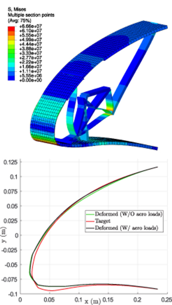
Figure 22. Half–scale model solution that is computed by the size optimization in terms of the Von Mises stress and a comparison between the deformed and target shapes.
Download figure:
Standard image High-resolution imageAfter this evaluation, the structural shape optimization is performed without the aerodynamic loads to reproduce the conditions of the experimental test.
4.2. Structural shape optimization
Starting from the solution obtained by the size optimization, an initial complete CAD model is generated. Particular attention has been devoted to achieving fillets inside the structure and gradual transitions along the skin to reduce the abrupt thickness changes.
The model is imported into Abaqus, and it is finely meshed using 10–node quadratic tetrahedron elements for both the internal structure and the skin. The static analysis results demonstrate that the stress level increases due to local concentrations that the previous medium–fidelity model cannot catch, up to a maximum value of 112 MPa inside the structure.
The shape optimization is used to spread the stress, thereby reducing the peak values in two critical regions. The first region is the same critical region on the right side of the full–scale model, inside the structure. The second region is the bottom part of the skin where the maximum curvature variation is achieved during the deformation. Hence, the shape optimization is applied to both the mechanism and the skin, and the complete 3D model is considered according to the second approach that is described in section 2.4. The process introduces shape changes around the critical regions to reduce the stress peaks. The corresponding results are reported in figure 23 and in figure 24 for the structure and the skin, respectively.

Figure 23. Solution improvement near the more critical region of the compliant rib during the structural shape optimization.
Download figure:
Standard image High-resolution image
Figure 24. Solution improvement near the more critical region of the skin during the structural shape optimization.
Download figure:
Standard image High-resolution imageThe results of the finite element analysis performed on the optimized model are reported in figure 25, together with shape quality comparisons. After the optimization process, the maximum stress in the structure decreases to 63 MPa; hence, the optimal solution can satisfy the stress constraint when the prototype is actuated. A comparison between the deformation before and after the shape optimization shows that the shape quality is preserved. The achieved deformation is substantially unchanged, and the final value of LSE is 2.7, which is the same as the value that was obtained after the size optimization.
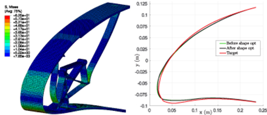
Figure 25. Half–scale model solution that is computed at the end of the optimization process in terms of the Von Mises stress and a comparison between the deformed and target shapes.
Download figure:
Standard image High-resolution image4.3. Experimental validation
Once the design of the half–scale prototype has been finalized and the detailed structural model has been obtained, it is manufactured and tested to validate the numerical solution and to study the overall behaviour of the adaptive droop nose from the experimental perspective.
The CAD model, which corresponds to the result of the shape optimization, is directly produced via a 3D printing technology, together with the kinematic chain that is conceived for actuating the compliant structure. The kinematic chain consists of a shaft, a cam and two rods. The sizes of these mechanical components are redesigned by taking into account their internal forces. Moreover, a very thick block is added in place of the front spar to ground the structure. The complete CAD model is shown in figure 26, and it is used as input for the SLS process, while figure 26 represents the corresponding manufactured prototype. The SLS technology enables its manufacture, together with that of the kinematic chain, in a single process. The prototype is composed of different parts that are connected by hinges. By selecting appropriate tolerances, it has been manufactured considering the interactions between the different parts to guarantee the proper relative motions. At the end of the process, the prototype is already assembled and cannot be disassembled. The effect of the clearance between all the kinematic parts is evaluated to assess the mechanism degree of freedom with respect to the manufacturing process and to the component tolerance and geometry.
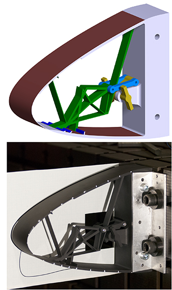
Figure 26. CAD model for the 3D printing manufacturing and compliant droop nose prototype manufactured by SLS technology.
Download figure:
Standard image High-resolution imageThe realized droop nose is actuated by rotating the shaft up to reach the maximum design deflection. The shaft is equipped with two handles that achieve the horizontal position when the shaft is rotated 70 deg. The experimental tests are performed outside the wind tunnel; hence, no aerodynamic loads are applied to the skin, and the corresponding deformed shapes that are computed in Sections 4.2 and 4.1 are used for the validation.
Two experimental verification approaches are considered: a qualitative comparison between the deformed shape that is achieved by the deployed prototype and the optimal numerical shape that is obtained at the end of the optimization procedure, and a computation of the experimental LSE.
In the first case, the experimental test is simply carried out by overlapping the deformed prototype with the numerical deformation that has been printed on a paper. The comparison, which is reported in figure 28, reveals satisfactory proximity between the two shapes, thereby confirming the validity of the adopted design procedure.
In the second case, the measurement of the experimental deformation is performed by a simple photogrammetry approach that is based on a camera that can identify specific markers that have been installed on the model. The device is equipped with 22 markers along the skin, which have been placed at the arc–length positions of the points that are used to compute the numerical LSE. These points have been identified on the CAD model that was uploaded on the SLS machine and checked on the prototype using a flexible ruler that was wrapped around the droop nose. Some pictures of the deformed model were captured with a Nikon D80 camera with a 10.2 Mpixels resolution and equipped with a 70–200 mm f2.8 lens, which was placed perpendicular to the droop nose cross–section. All pictures were post–processed to apply the corresponding lens correction. Then, a selected picture was digitally recognized, and the marker positions were used to reconstruct the experimental deformation. Several intermediate deflections were identified to achieve the 16 deg of equivalent deflection that corresponds to the target shaft rotation of 70 deg. Starting from the undeformed configuration, the 6 deg and the 16 deg of equivalent deflection are shown in figure 27. The optical recognition of the last picture is used to plot the corresponding curve and to compute the experimental LSE. The comparison between the curve that corresponds to the 70 deg of shaft rotation, the target curve and the curve obtained by the numerical analysis are reported in figure 29. The experimental curve is between the numerical and the target curves, showing how the shape quality of the prototype appears better than the numerical one. The corresponding LSE is evaluated, and a value of 2.3 mm is obtained. The comparison between this value and the numerical LSE, which was obtained from the high–fidelity model used by the shape optimization and it is equal to 2.7 mm, provides a quantitative validation that shows a satisfactory numerical/experimental correlation. After the target shape was recognized, the shaft rotation was increased up to 75 deg to test the prototype behaviour beyond the target deflection. The corresponding curve is also reported in figure 29, and it shows that the deflection further increases, deforming the upper part of the skin downwards. After that, the shaft rotation has been reduced to completely unload the prototype and to match the undeformed shape. This confirms the elastic behaviour of the prototype that did not exceed the stress limit of its material. These outcomes prove the effectiveness of the proposed procedure in terms of both the design capability and the achievement of a feasible manufacturing solution.
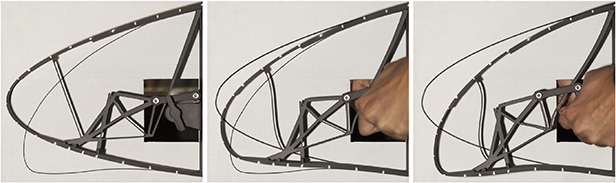
Figure 27. Experimental deformation steps for shape recognition.
Download figure:
Standard image High-resolution image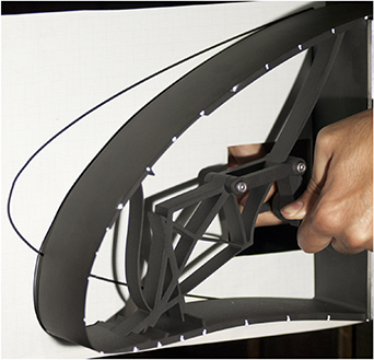
Figure 28. Experimental test for the identification of the maximum deflection shape corresponding to a 70 deg rotation of the shaft.
Download figure:
Standard image High-resolution image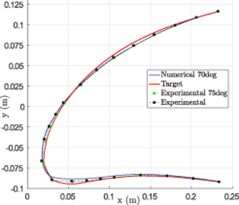
Figure 29. Comparison between experimental and numerically deformed shapes.
Download figure:
Standard image High-resolution image
5. Conclusions
This paper has described a design procedure for morphing wing devices based on compliant structures. After a topology optimization for the synthesis of the internal structure, a size optimization is applied to obtain solutions that feature various materials and geometric scales, thereby improving the performances in terms of the kinematic requirement. Then, a structural shape optimization is performed on more detailed models to reduce the stress concentrations inside the compliant structures and to finalize the CAD design details. Using materials other than those taken into account during the topology optimization is like considering the topology solution to be material–independent. This independence is not generally true; however, the proposed optimization procedure has been shown to improve the topology solution even if the behaviour of the original material differs from the behaviour of the current material. For example, this improvement is the observed for non-linear materials when the topology optimization is performed while considering linear behaviour.
The proposed approach has been applied to the topology solution of a compliant droop nose that was designed to deploy in high–lift conditions. A superelastic material was assigned to the compliant structure after the topology optimization was carried out. The material parameters of Nitinol were used in the corresponding finite element models, and the characteristic temperatures were selected according to the aircraft operating range. The numerical results were utilized to validate the developed optimization procedure and the use of superelastic material in combination with compliant structures. The optimization procedure was applied considering the reference temperature, and a verification at the limit temperatures confirmed the robustness of this approach. The use of Nitinol, in combination with the size optimization, enhanced the performance of the available design in terms of kinematic capabilities. The shape optimization results have shown that superelastic materials not only improve the solution from the morphing shape quality perspective but also may ensure the structural feasibility when conventional aeronautical materials are not able to satisfy the strength requirements. Although the numerical results are promising and enable the validation of the whole optimization procedure, experimental investigations are necessary to assess morphing solutions that are based on the use of Nitinol. An experimental characterization of the material should be carried out, and the impacts of the available manufacturing technologies should be evaluated. Since its mechanical characteristics depend on the alloy composition, manufacturing process, thermal treatments and operative temperatures, a substantial amount of work is required to better understand if superelastic materials can be adopted in the design of aeronautical structures. Studies on their fatigue behaviour must be performed.
The design of a half–scale prototype enabled the validation of the optimization procedure from the experimental perspective. The corresponding scaled model is characterized by the same initial topology solution as was used for the design of the full–scale model that was based on the use of Nitinol. The prototype is made of a polyamide-based material, and it was manufactured by 3D printing technology. The size optimization was applied to determine the thickness parameters according to the requirements of the new geometry and the new material. The shape optimization facilitated the reduction in the stress peaks inside the prototype. The experimental tests enabled the validation of both the entire procedure and the functionality of the considered morphing droop nose concept. The manufacturing process and the subsequent results demonstrated that the proposed design approach is also suitable for scaling compliant solutions from the structural perspective.
The proposed optimization methodology is general and can be applied to the design of various active camber morphing devices that are based on compliant structures. The procedure was implemented to be extended to the optimization of the morphing flap, the aileron and all kinds of morphing leading and trailing edges. Moreover, the design procedure can be applied to adapt an existing topology solution, based on the compliant structure concept, to a modified external geometry. This adaptation can consider the progressive spanwise airfoil change that is due to the wing tapering. Parallel studies are focused on the use of the same procedure to adapt the design of the compliant droop nose, which is discussed in this paper, to all cross–sections along the wingspan. Via this approach, the complete morphing device can be installed on the three–dimensional wing–box to evaluate their mutual interactions and to perform aeroelastic analyses.
Acknowledgments
The AirGreen2 Project has received funding from the Clean Sky 2 Joint Undertaking, under the European's Union Horizon 2020 research and innovation Programme, under grant agreement No 807089 – REG GAM 2018 – H2020-IBA-CS2-GAMS-2017.