

Abstract
This paper proposes an innovative dual-functional aeroelastic metastructure that effectively suppresses wind-induced structural vibrations under either pure aerodynamic galloping or concurrent galloping and base excitations, while simultaneously harnessing the vibratory energy to potentially allow for self-powered onboard low-power sensing applications. Two configurations are theoretically and experimentally analysed and compared, one consisting of simply regular locally resonating masses subjected to no external forces, while the other comprising locally resonating bluff bodies which experience additional aerodynamic galloping forces. Numerical investigation is conducted based on an established aero-electro-mechanically coupled model. Wind tunnel wind tunnel and base vibration experiments are carried out using a fabricated aeroelastic metastructure prototype to characterize the energy transfer mechanisms and validate the numerical results. The mutual effects of key system parameters, including the frequency ratio, mass ratio, load resistance and electromechanical coupling strength, on the dual-functional capabilities are examined, providing a comprehensive design guideline for efficiently enhancing the energy transfer and conversion. Experimentally, the galloping displacement of the primary structure is attenuated by 78% with a measured power output of 2.63 mW from a single auxiliary oscillator at a wind speed of 8 m s−1. This research opens new possibilities for designing novel metastructures in practical scenarios where both wind-induced vibration suppression and energy harvesting are crucial.
Export citation and abstract BibTeX RIS

Original content from this work may be used under the terms of the Creative Commons Attribution 4.0 license. Any further distribution of this work must maintain attribution to the author(s) and the title of the work, journal citation and DOI.
1. Introduction
Wind-induced vibrations can cause serious damage to buildings, bridges, and offshore structures. There are many scenarios that require protection from wind-induced vibration, such as bridge collapses [1, 2], skyscraper wind-resistance design [3, 4], arm masts of traffic lights [5, 6] and road signs [7, 8], cranes [9, 10], aerofoils [11, 12], and more. Traditional solutions for passive vibration suppression primarily involve the use of tuned mass dampers [13, 14], nonlinear energy sink [15, 16], etc. However, these approaches have drawbacks, such as adding extra-large lumped mass to the primary structure, post modification to the geometry of the structure, and challenges of post installation, which can impact their functionality. To address these issues, a new approach based on integrating distributed periodic local resonators (LRs) to work as vibration absorbers, known as metastructures, has been proposed recently [17, 18]. Metastructures are inspired by the traditional passive low degree-of-freedom (DOF) vibration absorber systems and recently emerged periodic phononic metamaterials [19–22]. They have shown potential for effectively suppressing vibrations without the need for additional excessive lumped mass [19, 23], alterations to the primary structure's geometry, post-assembly complications, or adverse impact on the manufacturing process of the primary structures. EI-Borgi et al [24] proposed a metamaterial beam with multiple different linear LRs which successfully achieve multiple bandgaps in the low frequency region. However, the bandgaps are very narrower and limit its applications. Therefore, graded frequency LRs [25–27], nonlinear elements [28–30], and bandgaps merging [31–34] and tuneable technologies [35–39] are considered in metastructures to suppress vibration in wider, adjustable and adaptive bandgaps. Lv et al [40] designed a tuneable elastic metamaterial beam using rotatable coupled dual beam LRs, which can continuously tune the bandgap and transmission properties of the metamaterial beam by changing the moment of inertia of the resonators in a wide frequency range. Xia et al [41] investigated the amplitude-dependent dynamics of a locally resonant metastructure beam with bistable attachments, demonstrating enhanced vibration attenuation bandwidth through a combination of linear resonant bandgap and nonlinear wideband attenuation effects. Xiao et al [31] reported a metamaterial beam by combining negative stiffness absorbers and rotation of flexural beams, which can merge two separate low-frequency bandgaps into a wider one through damping magnification from negative stiffness springs. Additionally, energy harvesting has been extensively explored over the past decade for the purpose of enabling self-powered microelectronics and wireless sensors for various monitoring applications. Electromechanical coupling in energy harvesting systems brings potentials for simultaneous power extraction from ambient vibration sources and vibration mitigation with the added electric damping [42–46]. For example, Hu et al [47] conducted an analytical study of a multifunctional system that combines acoustic-elastic metamaterial with energy-harvesting capabilities, achieving simultaneous vibration suppression and energy harvesting through the utilization of a double-valley phenomenon and parametric optimization. An amplitude-robust nonlinear dual-functional metastructure is presented by Xu et al [26], integrating alternate bistable and monostable-hardening mechanisms to achieve significantly enhanced simultaneous vibration suppression and energy harvesting in comparison to pure bistable or pure monostable nonlinear structures by preserving a wide bandgap even under high accelerations, attenuating the unwanted resonance peaks outside the bandgap, while generating power across a broad bandwidth. Sugino and Erturk [48] explored a multifunctional metamaterial beam in energy harvesting and vibration reduction, which can generate power from LRs and form maintain capabilities of vibration suppression due to the formation of bandgap simultaneously.
While most of the state-of-the-art research has been conducted on metastructures for vibration suppression under base vibrations [25, 26, 41, 49–51], there has been very limited study on their effectiveness against wind-induced vibrations [52]. Tian et al [53] presented a theoretical model of a metamaterial stiffened plate for supersonic flutter analysis, demonstrating that the inclusion of multiple cantilever beam resonators can effectively suppress broadband vibrations and enhance flutter stability in supersonic plates. And they also explored a metamaterial design featuring tunable-stiffness nonlinear oscillators for suppressing vibration and flutter in supersonic plates [54]. Basta et al [55] analytically studied flutter suppression of an airfoil using an array of distributed nonlinear vibration absorbers, increasing the flutter speed by 84%. However, the quadratic and cubic stiffness nonlinearities of the absorbers were shown to degrade the performance as they adversely amplify the oscillation amplitudes beyond flutter.
On the other hand, there are many research efforts [56–59] in wind energy harvesting with high performance power output to achieve self-powered electronics. Liao et al [56] investigated the voltage output performance and power characteristics of a joint-nested structure piezoelectric wind energy harvester (JNS-PWEH) compared to a conventional single-cylinder PWEH. The results show that the JNS-PWEH achieves over 10 times significant improvements in power generation of 2.2 Mw at 300 kΩ. A combing windward and leeward four-fin cylinder wind energy harvester is reported for enhanced energy harvesting in a broader wind speed range.
Zhao et al did lots of pioneering research works [59, 60] in galloping energy harvester for improving their outputs under concurrent wind and base excitations. For example, a broadband concurrent wind and base vibratory energy harvester is proposed with a mechanical stopper to effectively energy harvesting, which can generate the maximum power of 3.8 mW at 19.1 Hz under concurrent wind and base excitations [59]. However, these harvesters still cannot generate enough power due to their low DOF structure and have single function. And metastructure is generally multifunctional, which can achieve vibration and energy harvesting simultaneously.
Given that wind-induced vibrations can potentially have detrimental impact on structures [1, 3], there is an essential need to address the gap and explore the potential of metastructures in the field of wind-induced vibration suppression and energy harvesting. This paper proposes a dual-functional aeroelastic galloping metastructure that aims to suppress wind-induced structural vibrations under either pure aerodynamic galloping or concurrent galloping and base excitation, and simultaneously harness kinetic energy to generate power for onboard low-power sensing and structural health monitoring. The objective is to provide a solution capable of reducing the damage caused by wind-induced vibrations and base excitations in various scenarios, for example, vibrations in buildings and structures like traffic light mast arms due to wind excitations, and vibrations in bridges exposed to concurrent wind and base excitations, and so on, where a few practical examples are shown in figure 1(a). The paper is organized as follows. Section 2 present the design and aero-electro-mechanically coupled modelling of the aeroelastic galloping metastructure; section 3 theoretically investigates the responses of the proposed structure to develop design guidelines by analysing the influence of key parameters on the dual-functionality, including mass ratio, frequency ratio, loading resistance and electromechanical coupling; section 4 presents the wind tunnel and vibration experiment results for a fabricated metastructure prototype; and conclusions are made in section 5.
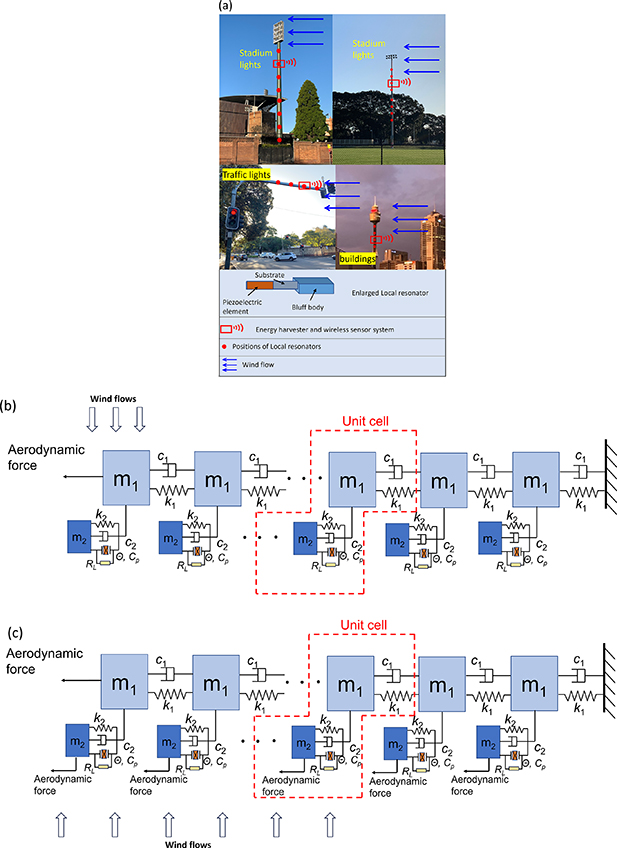
Figure 1. Applications in real world and design of aeroelastic metastructure (a) aeroelastic metastructure application scenarios; physical model of the proposed aeroelastic galloping metastructure, with 1st to nth unit cell from the free end to the fixed end: (b) Configuration I without wind flows excitation on m2; (c) Configuration II with extra wind flows excitation on m2.
Download figure:
Standard image High-resolution image2. Design and theoretical modeling
This section presents the design and modeling of the aeroelastic metastructure. Two configurations are discussed, and the aero-electro-mechanical coupled model is built based on a lumped parameter chain.
2.1. Design
We consider two configurations for comparison, distinguished primarily by the characteristics of the masses of the LRs. Specifically, in Configuration I, the locally resonating masses are simply regular masses subjected to no external forces, exhibiting an electro-mechanical coupling behaviour; while in Configuration II, the locally resonating masses consist of bluff bodies with equal weights, which also experience aerodynamic galloping forces applied to them, displaying an aero-electro-mechanical coupling behaviour. From a more practical perspective, Configuration I is designed for internal installation, inside the flexible supporting beams or columns; while Configuration II is appropriate for scenarios where external installation exposed to ambient environment is permissible. For the mechanical-to-electrical energy conversion, piezoelectric transduction is incorporated by inserting piezoelectric elements to the LRs.
Figures 1(b) and (c) depicts the physical model of the proposed aeroelastic galloping metastructure, which consists of a long chain including n lumped masses that are elastically connected, representing the primary structure, and periodical electromechanical locally resonating oscillators attached to each primary mass to serve as both vibration absorbers and energy harvesters. The LRs absorb and dissipate a portion of the vibration energy from the primary structure while converting the remaining portion of the transferred energy into electricity through electromechanical coupling. The primary structure is subjected to aerodynamic galloping excitation induced by a bluff body at its free end, which results in an aerodynamic galloping force acting on the lumped mass positioned at the free end of the primary chain, representing the location of the bluff body. In scenarios involving concurrent wind and base excitations, the fixed end of the structure will further be subjected to external base vibration. Since our focus is on the power conversion efficiency of the harvesters as well as the impact of the coupling strength and backward electrical damping on the system's dynamic responses, rather than the sophisticated power extraction and regulation mechanisms, therefore, we employ a simple AC circuit consisting of a simple resistive load connected to the piezoelectric element in each cell. For the purpose of proof-of-concept, prototypes of Configuration I and Configuration II (with three LRs, as an example, shown in figure 11) are fabricated. Which wind tunnel and base vibration experiments are carried out, with details given in section 4.
2.2. Theoretical modeling
The governing equations of the system for two configurations can be expressed, respectively, as follows, by considering the aero-electro-mechanical coupling between the mechanical primary structure, LRs, piezoelectric elements connected to the AC circuits, and the external aerodynamic loading: for Configuration I,
and for Configuration II
where m1
, c1
, k1 are the mass, damping, stiffness of each cell on the primary chain, respectively; u1i
represents the displacement of the ith primary mass; m2
, c2
, k2 are the mass, damping, stiffness of each LR; u2i
is the displacement of the ith LR; vi
is output voltage of the piezoelectric element on the ith oscillator; θ is the electromechanical coupling; RL
is the connected loading resistance in the circuit; and CP
is the capacitance of the piezoelectric element. The displacement of the base excitation is given by  . F1 and F2i
are the aerodynamic forces due to galloping, exerted on m1 at the free end of the primary chain and m2 in the ith cell, respectively. The aerodynamic model is built based on the quasi-steady hypothesis [61], given by
. F1 and F2i
are the aerodynamic forces due to galloping, exerted on m1 at the free end of the primary chain and m2 in the ith cell, respectively. The aerodynamic model is built based on the quasi-steady hypothesis [61], given by
where ρ is the air density; Aj and Bj are aerodynamic coefficients; h1 and h2 are the heights of windward side of bluff bodies; L1 and L2 are the lengths of windward side of bluff bodies, where subscript 1 and 2 represent bluff body 1 on the primary structure and bluff body 2 on the LRs, respectively.
The governing equation is further nondimensionalized based on the following dimensionless parameters,
and the dimensionless form of the governing equation is given by the following form for two Configurations: for Configuration I
and for Configuration II
By introducing the state vector Si ,
The governing equations can be transformed into the following state-space form:

In equation (8), the coefficient matrices are given by: for Configuration I,
and for Configuration II,
In the above matrices, we have
Equation (8) can be numerically solved using the Runge–Kutta algorithm to obtain the mechanical displacement responses and electrical outputs.
2.3. Cut-in wind speed of galloping
The cut-in wind speed ucr can be obtained through analysing the linearized governing equations. Because the aerodynamic loading will induce an equivalent negative damping effect [44], galloping takes place when the negative damping overcomes the positive damping, which is the sum of intrinsic mechanical damping and the backward electrical damping resulting from the piezoelectric energy harvesting process. Based on this principle, the cut-in wind speed is theoretically predicted by making the coupled damping equal to zero. The matrix Ci reflects that the galloping cut-in wind speed will be influenced by the load resistance r, and the cross-section geometry of the bluff body on both the primary structure and the LRs (geometry determines the values of f11, f12, f21, and f22). Introducing

The relationship of cut-in wind speed with load resistance for certain cross-section geometries of bluff bodies can be determined by examining the features of values of βm , which are the eigenvalues of the matrix Ci. I is the identity matrix. For an aeroelastic metastructure containing n unit cells, there are 2n sets of eigenvalues, which are complex conjugates. The system is stable if the real parts of all sets of eigenvalues are negative; otherwise, the system transitions to unstable if the real parts of any one set of eigenvalues become positive. In the following numerical investigations, unless specified otherwise, the parameters are taken as α= 0.4, λ= 0.3, ζ1 = ζ2 = 0.01, ke = 7.7296 × 10⁻⁵ , r= 1.644, f11 = 0.015, and f13= −0.1685. Moreover, for Configuration I, the aerodynamic coefficients in the LRs are set to f21 = 0 and f23 = 0; for configuration II, they are set to f21 = 0.0375 and f23= −0.4213. For better consistency with the experiments, the number of cells is set to n= 3. The relationship of cut-in wind speed ucr with load resistance r is plotted in figure 2. ucr of Configuration II is lower than that of Configuration I; more importantly, compared to the original primary structure without LRs, Configuration II is capable of reducing the cut-in speed, which is a major component for mitigating wind-induced vibration. However, the overall galloping suppression performance needs to be evaluated by further comparing the steady-state oscillation amplitude of the system beyond the cut-in speed, which will be discussed in the following section. By enlarging figure 2(a), it is found in figures 2(b) and (c) that Ucr of the two configurations both slightly vary with r, which increase firstly and then decrease with increasing r. Maximum Ucr are obtained as r approximates 1, indicating the electrical damping reaches maximum.
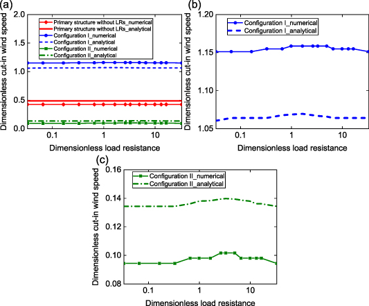
Figure 2. Variation of analytical and numerical cut-in wind speed with load resistance for three configurations, including primary structure without LRs, Configuration I and Configuration II. (a) Comparison of cut-in wind speeds for three configurations; (b) enlarged figure, only for Configuration I; (c) enlarged figure, only for Configuration II.
Download figure:
Standard image High-resolution image3. Results and discussion
In this section, the baseline performances of the two aeroelastic metastructure configurations are evaluated and compared concerning their capability of attenuating the vibration of the primary structure and generating power, to gain a fundamental understanding of their characteristics and effectiveness in energy transfer and harvesting. Performances of the metastructure are investigated numerically under pure wind excitation, as well as concurrent wind and base excitations.
3.1. Under pure wind excitation
Firstly, the dynamic and electrical responses of the two configurations are examined under pure wind excitation. The average power output from each unit cell is calculated by Vi RMS 2/r, where Vi RMS is the root mean square (RMS) generated voltage in the ith cell.
The findings shown in figure 3 demonstrate that the two proposed aeroelastic metastructure configurations both exhibit effective performance in suppressing the vibration of the primary structure as well as generating power. Notably, Configuration I, without the locally resonating bluff body in each cell, considerably increases the cut-in wind speed compared to the pure primary structure without the LRs, suggesting that it can effectively attenuate galloping vibrations at low wind speeds. On the other hand, Configuration II that includes bluff bodies in the locally resonating unit cells, despite having a slightly lower cut-in wind speed, shows strong potential in suppressing galloping vibration at high wind speeds. Beyond the cut-in wind speed, steady-state limit-cycle oscillations (LCOs) occur. It is seen that Configuration II yields a much smaller slope of displacement-wind speed variation than that of the pure primary structure, further benefits the galloping suppression. Figure 3(b) displays the relationship between the vibration frequency and reduced wind speed. For Configuration I, the vibration frequency remains constant at approximately 0.51, which is close to the second natural frequency of the metastructure system, resulting in an out-of-phase motion. Conversely, configuration II exhibits a vibration frequency of approximately 0.27, close to the first natural frequency of the system, resulting in an in-phase motion. The output power from the 1st unit cell of the two configurations is shown in figure 3(c), where Configuration II exhibits a higher output power than Configuration I in the considered wind speed range. In addition, phase trajectories are plotted for showing the formation of LCO and its evolution process. The bigger the covered area of phase trajectories is, the larger the oscillation displacement is. As shown in figures 3(d)–(f), LCOs are observed as the wind speed surpasses the corresponding cut-in wind speeds of the configuration. Both Configuration I and II can effectively mitigate the galloping amplitude of the primary structure.
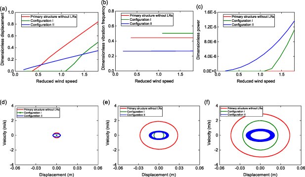
Figure 3. Response comparison for three structures: primary structure without LRs, Configuration I, and Configuration II. (a) Nondimensional displacement, (b) nondimensional oscillation frequency, and (c) nondimensional power with reduced wind speed. Associated phase trajectory at different wind speeds (d) ua = 0.54, (e) ua = 1.27, (f) ua = 1.82.
Download figure:
Standard image High-resolution imageThe influences of key system parameters, including the frequency ratio, mass ratio, load resistance and electromechanical coupling strength, on the dynamic behaviours of the proposed aeroelastic metastructure as well as the energy transfer and harvesting efficiency are subsequently investigated. Figure 4 investigates the effects of frequency ratio  , defined as the ratio of the natural frequency of the LR to that of the primary oscillator in each cell.
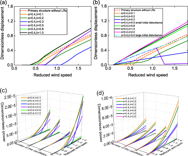
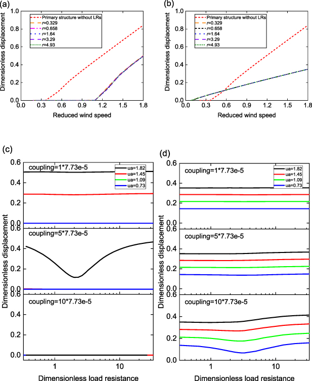
Figure 4. Displacement and power responses at different frequency ratios λ. (a), (b): Variation of dimensionless RMS displacement p1_RMS at the free end of the aeroelastic metastructure with reduced wind speed; (c), (d): variation of dimensionless power from each local resonator (No. 1 ∼ 3) as well as total power (No.4) with reduced wind speed. (a), (c): Configuration I; (b), (d): Configuration II.
Download figure:
Standard image High-resolution imageFirstly, we evaluate the vibration suppression performance by examining the dimensionless RMS galloping displacement of the primary mass m1 at the free end of the aeroelastic metastructure in the 1st cell (see figure 1), i.e. p1_RMS. The variations of p1_RMS with various λ are compared to that of the primary structure without the LRs, as shown in figure 4(a) for Configuration I and figure 4(b) for Configuration II. For Configuration I, it is seen that when the frequency ratio λ is below or equal to 0.3, the galloping displacement of the primary structure is effectively suppressed within the considered wind speed range (ua 1 ⩽ 1.82), meanwhile, the cut-in wind speed is significantly increased. The galloping suppression performance improves with the increase of λ. However, when λ increases to a medium value of 0.5, although the metastructure is able to attenuate vibration at low wind speeds and slightly increase the cut-in wind speed, the galloping suppression performance is degraded at high wind speeds, where the displacement unfavourably increases beyond the case without LRs. When λ further increases and exceeds 0.8, the aeroelastic metastructure fails to increase the cut-in speed or suppress the vibration displacement. In Configuration II, although the cut-in wind speed is not reduced, it effectively attenuates the vibration of the primary structure right after LCO manifests when λ ⩽0.3; moreover, similar to Configuration I, the galloping suppression performance also improves with increasing λ. Nevertheless, any λ beyond 0.5 is ineffective in suppressing galloping oscillation. Overall, in both aeroelastic metastructure configurations, the optimal frequency ratio should be carefully tuned to a small value up to 0.5 for effective galloping suppression. It is worth noting that this conclusion differs from the case with base vibration suppression metastructures [26, 47, 49], where the linearized natural frequency of the LRs should always be tuned to approach that of the primary structure in each cell, i.e. λ ≈ 1.0, for optimal vibration suppression capability.
The energy harvesting capability of the aeroelastic metastructure as the frequency ratio changes is investigated in figures 4(c) and (d). Generally, in both configurations, the harvester in the 1st cell at the free end of the chain produces the highest power compared to others. The total output power combinedly from all unit cells corresponds to No. 4 on the horizontal axis of 'number of the oscillator' for convenient plotting. The aeroelastic metastructures effectively generate power when λ gradually increases up to 0.5; however, beyond this value, the power output is minimal. This is as expected since any λ beyond 0.5 is ineffective in suppressing the oscillation of the primary structure, indicating the inability to transfer kinetic energy to the locally resonating harvesters for the subsequent vibratory-to-electrical power conversion. It is evident Configuration II outperforms Configuration I by generating almost three times more power. This is reasonable since the inclusion of bluff bodies in the LRs enhances the capability to capture power from wind flows.
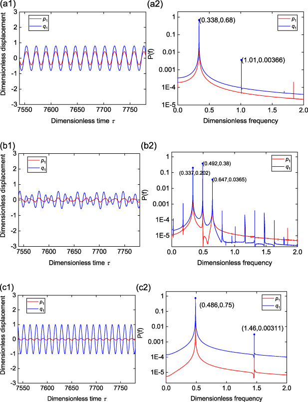
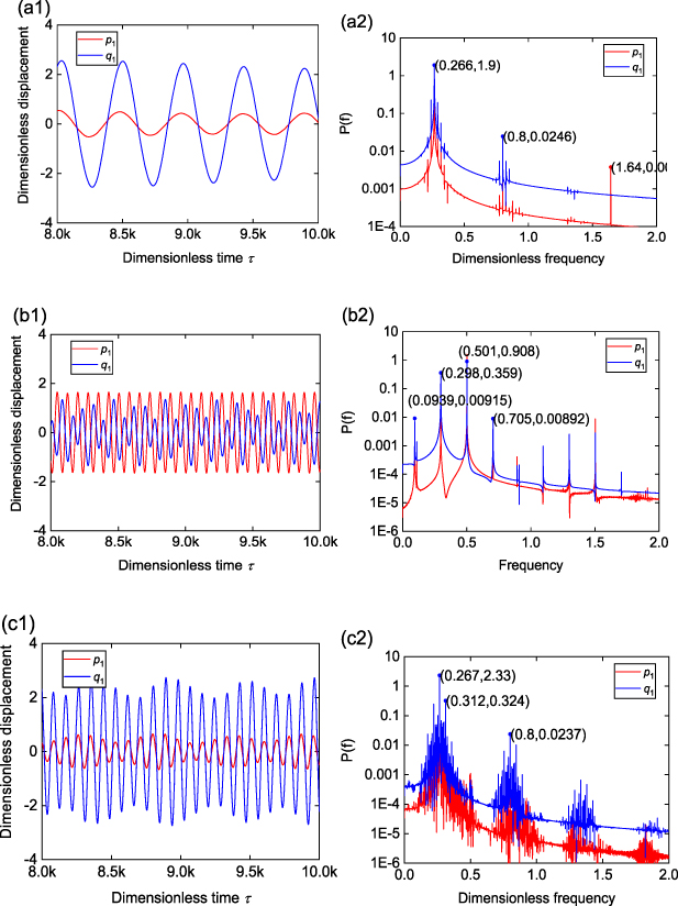
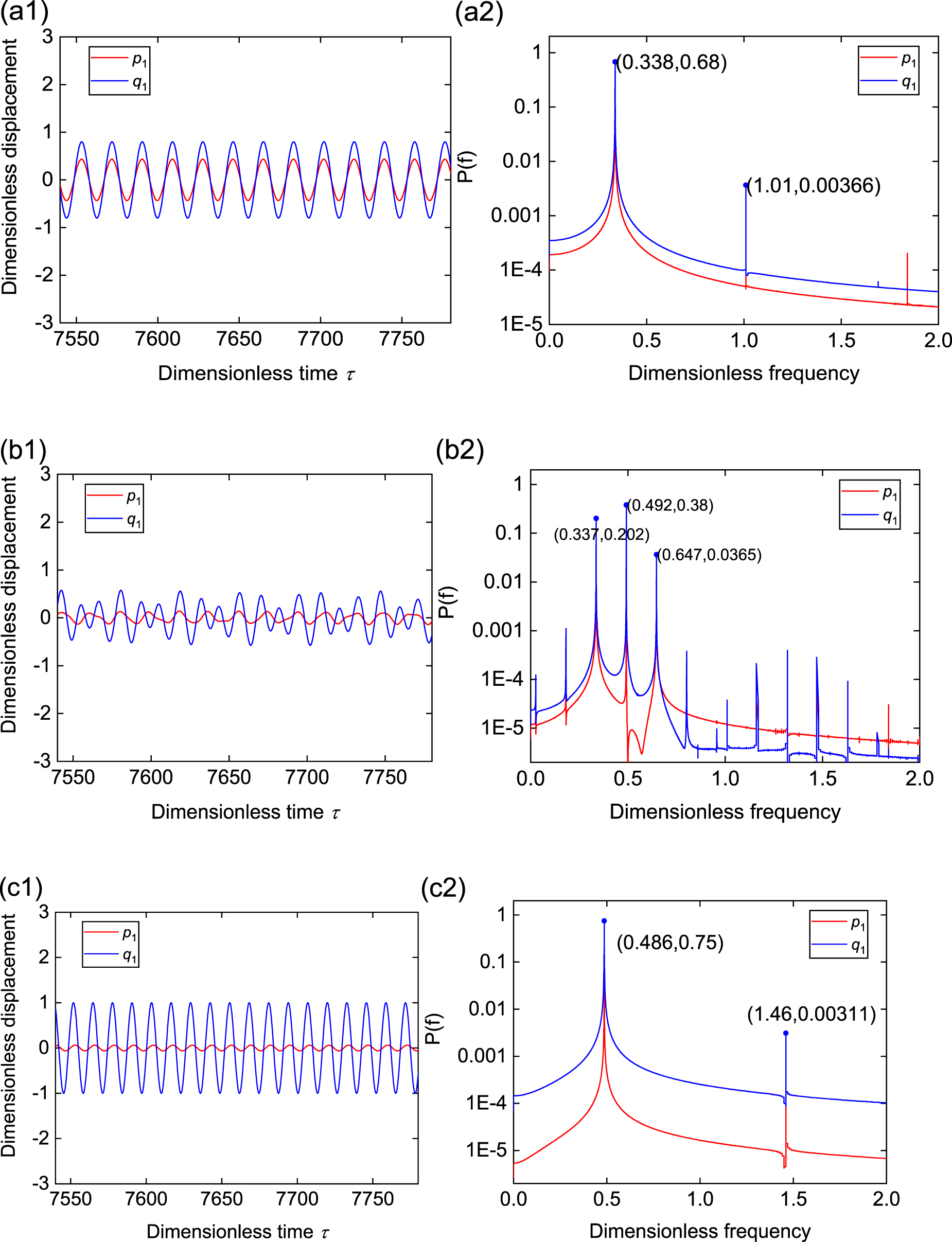
It is interesting to see from figure 4(b) that at λ= 0.5, the galloping displacement of the primary structure in Configuraiton II notably decreases at a wind speed around ua 1 = 1.20 if the initial disturbance is small. The time histories of displacements of the primary mass m1 and locally resonating mass m2 in the free-end unit cell, i.e. p1 and q1, at different wind speeds are shown in figure 5, along with the power spectrums. When this jump down occurs, extra frequency components appear, and the oscillations of m1 and m2 become aperiodic, as shown in figure 5(b1–b2). Moreover, the aeroelastic metastructure experiences a sharp frequency shift from 0.338 to 0.486 at around ua 1 = 1.20, as presented in figure 5(d3). A further examination on the responses in figure 5(c1–c2) and (d1–d2) reveals that with a large initial disturbance, the oscillation of the system is dominated by the galloping of the primary bluff body; in contrast, with a small initial disturbance, the responses are dominated by the auxiliary bluff bodies in the unit cells. The later case results in more wind energy transfer to the auxiliary bluff bodies compared to the primary bluff body, leading to a signaficant suppression of the primary structure's oscillation at high wind speeds. However, we should stress that in practical scenarios, unavoidable gusts or turbulences are ubiquitous, posing challenges to achieve such a significant vibration suppression that requires a small initial disturbance.
Download figure:
Standard image High-resolution image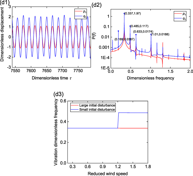
Figure 5. Time histories and FFT results for configuration II. (a1–a2) ua 1 = 0.73, (b1–b2) ua 1 = 1.09, (c1–c2) ua 1 = 1.82 (small initial disturbance, downward), (d1–d2) ua 1 = 1.82 (large initial disturbance, upward), and (d3) variation of the vibration frequency with wind reduced wind speed including large initial disturbance (upward) and small initial disturbance (downward).
Download figure:
Standard image High-resolution imageIn figure 6, we investigate the effect of mass ratio  on the mechanical and electrical responses of the aeroelastic metastructure. For Configuration I (figure 6(a)), with the increase of α, the galloping suppression performance firstly improves then degrades. There is an optimal α= 1.0 where the galloping displacement is fully suppressed within the wind speed range of interest; when α is beyond 5.0, there is no benefit as the displacement even increases compared to the initial primary structure. In Configuration II (figure 6(b)), the optimal galloping suppression performance is achieved at a much smaller α = 0.2, with a substantially increased cut-in wind speed and reduced vibration amplitude. It is worth noting that with Configuration II, α should be kept at small values, which is another distinct characteristic as compared to the metastructures designed for base vibration suppression, where larger mass ratios improve the vibration suppression efficiency [18, 23, 47]. The power output variations in figures 6(c) and (d) show a monotonic increasing trend with increasing α. In Configuration I, the 1st cell at the free end of the system generates the highest power; while in Configuration II, it appears the distributed cells yield comparable power levels. Overall, if the function of energy harvesting is prioritised, α should be tuned to as small as possible.
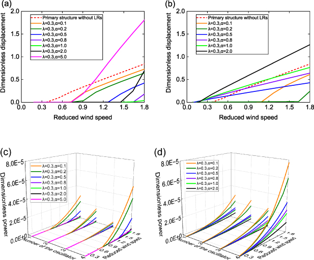
Figure 6. Displacement and power responses at different mass ratios α. (a), (b): Variation of dimensionless RMS displacement p1_RMS at the free end of the aeroelastic metastructure with reduced wind speed; (c), (d): variation of dimensionless power from each local resonator (No.1 ∼ 3) as well as total power (No. 4) with reduced wind speed. (a), (c): Configuration I; (b), (d): Configuration II.
Download figure:
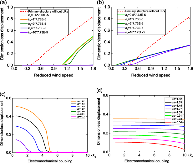
Standard image High-resolution imageFigure 7 investigates the influence of the electromechanical coupling strength in the LRs on the performance of galloping suppression and wind power extraction. In Configuration I, the galloping amplitude is significantly affected by the coupling strength, as can be seen in figures 6(a) and (c). Increasing the coupling strength remarkably improves galloping suppression by decreasing the galloping amplitude as well as increasing the cut-in wind speed, as a result of the increased backward electrical damping. When ke is increased beyond 3.865 × 10⁻⁴ (i.e. 5 × 7.73 × 10−5, figure 7(c)), the cut-in wind speed is dramatically increased by the large electrical damping, and galloping of the primary structure is fully attenuated to zero within the considered wind speed range. Conversely, the coupling strength only has minimal influence on the galloping amplitude in Configuration II, particularly at high wind speeds. It is deduced that the oscillation of the added bluff bodies in the unit cells primarily relies on the wind excitation and is not obviously impacted by the electrical damping.
Download figure:
Standard image High-resolution image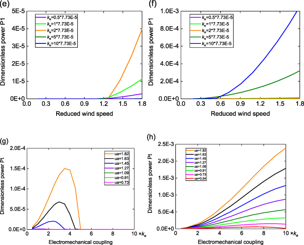
Figure 7. Displacement and power responses at different electromechanical coupling strengths ke . Variation of dimensionless RMS displacement p1_RMS at the free end of the aeroelastic metastructure with (a), (b) reduced wind speed, and (c), (d) electromechanical coupling; (e), (f) variation of dimensionless power Pave_1 in the free end cell of the aeroelastic metastructure with reduced wind speed; (g), (h) variation of total power with electromechanical coupling. Left column: Configuration I; right column: Configuration II.
Download figure:
Standard image High-resolution imageAs for the generated power, there exists a respective optimal coupling strength at each wind speed in Configuration I for highest power output, either in individual cells (figure 7(e), Cell 1 as an example) or from the aeroelastic metastructure combinedly (figure 7(g)), similar to a typical galloping energy harvester as we analysed in [44]. Therefore, selection of a proper coupling strength for Configuration I depends on the priority of the intended function. On the contrary, the power output appears to monotonically increases with increasing coupling strength in Configuration II. This is because there is no longer a competitive relationship between the suppressed displacement amplitude and improved energy conversion efficiency under strong coupling. Therefore, with Configuration II, it is always favourable to maximize the electromechanical coupling.
The impact of load resistance on the galloping suppression and power extraction performances is analysed in figure 8. When a weak electromechanical coupling is employed, as shown in figures 8(a) and (b), it is observed that the loading resistance has minimal influence on the galloping suppression performance in the two configurations. However, by further varying the coupling strength in figures 8(c) and (d), it is found that tuning the load resistance to an optimal value under medium or strong coupling can enhance galloping suppression in both configurations. Since the impact of coupling strength on the behavior of Configuration I is more pronounced than that of Configuration II (figure 7), tuning to the optimal load resistance in Configuration I leads to a much more evident improvement in suppressing the displacement amplitude. At a strong coupling of 7.73 × 10⁻⁴ (i.e. 10 × 7.73 × 10−5, figure 8(c)), the displacement in Configuration I is suppressed to zero. As for the power output, in Configuration I, there exists one optimal load resistance that produces a power peak under weak coupling, and two of them that yields two power peaks of equal amplitudes when the coupling gets stronger, consistent with the typical piezoelectric galloping energy harvester characteristic [44]. However, in Configuration II, the load tuning task is simpler as there is always a single optimal load resistance, the value of which is not noticeably affected by the coupling strength.
Download figure:
Standard image High-resolution image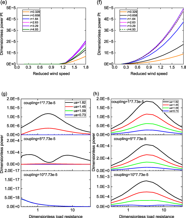
Figure 8. Displacement and power responses at different load resistances r. Variation of dimensionless RMS displacement p1_RMS at the free end of the aeroelastic metastructure with (a), (b) reduced wind speed, and (c), (d) load resistance; (e), (f) variation of total power with reduced wind speed; (g), (h) variation of dimensionless power Pave_1 in the free end cell of the aeroelastic metastructure with load resistance. Left column: Configuration I; right column: Configuration II.
Download figure:
Standard image High-resolution image3.2. Under concurrent wind and base excitations
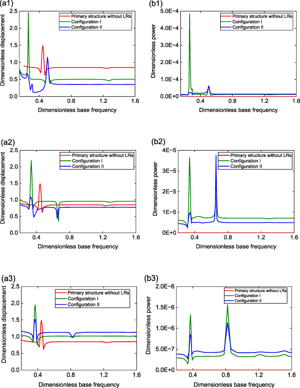
In this section, we explore the influence of mass ratio α and frequency ratio λ on the performance of vibration suppression and energy harvesting under concurrent wind and base excitations. The dimensionless base acceleration is fixed at 0.011 65, and the wind speed is constant at ua 1 = 1.82. Five cases are discussed. In figure 9(a1–a3), α is set to 0.4 while λ increases from 0.3 to 1.0. It is seen that, similar to the pure galloping excitation scenario, the vibration suppression degrades with increasing λ, in particular at off-resonance. In terms of the at-resonance synchronization region (i.e. lock-in region, where galloping frequency and base excitation frequency are locked into each other [62]), Configuration II is able to reduce the peak displacement when λ⩽ 0.5, although the location is shifted due to the addition of the LRs. In figure 9(a1, a4–a5), we fixe λ at 0.3 while vary α between 0.2 and 1.0. Again, like the pure galloping case, the overall vibration suppression performance degrades as α increases. Moreover, the highest power output is obtained at the smallest α and λ employed in the investigation (figure 9(b4)). Therefore, it is recommended that small α and λ should be chosen for improving vibration suppression and energy harvesting simultaneously under concurrent excitations.
Download figure:
Standard image High-resolution image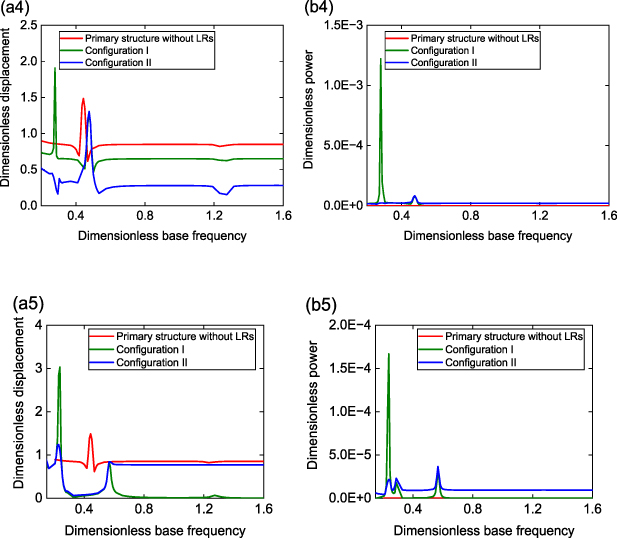
Figure 9. Responses under concurrent excitations of an dimensionless acceleration of 0.011 65 and an reduced wind speed of 1.82 at (a1–b1) α= 0.4, and λ= 0.3, (a2–b2) α= 0.4, and λ= 0.5, (a3–b3) α= 0.4, and λ= 1.0, (a4–b4) α= 0.2, and λ= 0.3, (a5–b5) α= 1.0, and λ= 0.3 for three configurations. (a1–a5) Variation of dimensionless displacement p1_RMS with dimensionless base frequency; (b1–b5) variation of dimensionless power Pave_1 in the free end cell of the aeroelastic metastructure with dimensionless base frequency.
Download figure:
Standard image High-resolution imageIn order to gain further insights into the working mechanism, we consider the case with α= 0.4 and λ= 0.3 in figure 9 for Configuration II, and analyze the time histories and power spectrums. At the frequency ωb = 0.25 and 0.50 (figures 10(b1) and (d1)), which match the first and second natural frequency of the aeroelastic metastructure, the response exhibits in-phase and out-of-phase motion, respectively, corresponding to the two displacement peaks in figure 9(a1). At these resonances, the oscillation frequency is predomenantly synchronized to the base excitation frequency, as evidenced in the power specturms given in figures 10(b2) and (d2). At off-resonance, as shown in figures 10(a1), (c1) and (e1), quasi-periodic vibration with strong modulated response phenomena [63] can be observed. The oscillation frequency is dominated at 0.266, which is the galloping frequency of the locally resonating bluff bodies, along with the associated 3rd harmonic frequency component at about 0.8, as seen in the corresponding FFT results. In particular, between the two synchrozation resonance peaks, the modulated response appears to lead to a displacement valley, dramatically suppressing the vibration of the primary structure (see figure 9(a1)).
Download figure:
Standard image High-resolution image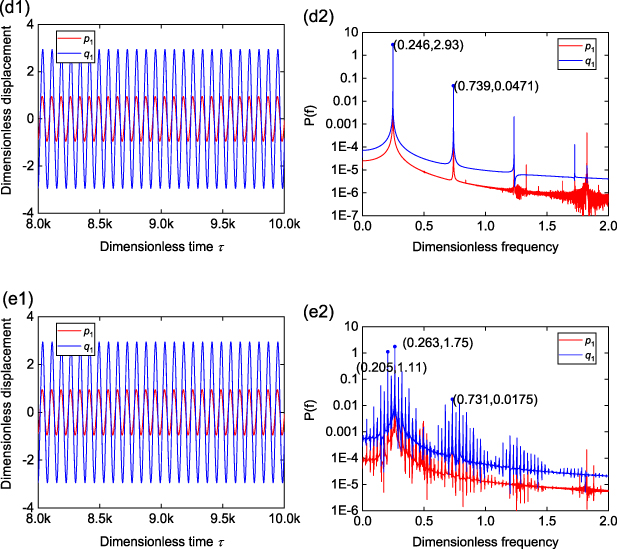
Figure 10. Time histories and power spectrums for configuration II under concurrent wind and base excitaions at different excited frequencies of (a1–a2) ωb = 1.64; (b1–b2) ωb = 0.50; (c1–c2) ωb = 0.31; (d1–d2) ωb = 0.25 and (e1–e2) ωb = 0.21, at an dimensionless acceleration of 0.011 65 and reduced wind speed of 1.82, with α = 0.4 and λ = 0.3.
Download figure:
Standard image High-resolution image4. Experimental verification
In this section, wind tunnel and base vibration experiments are conducted using a fabricated aeroelastic metastructure prototype to characterize the energy transfer mechanisms and validate the numerical results of vibration suppression and energy harvesting.
Figure 11 shows the experimental setup with the fabricated prototype. Configurations I and II are presented in figures 11(a) and (b), respectively. The primary structure consists of an aluminium cantilever with a square-sectioned bluff body connected at the free end, and three (pairs of) auxiliary beams attached to the primary cantilever to work as locally resonating absorbers as well as energy harvesters. Piezoelectric sheets are bonded to the attached end of the auxiliary beams to convert the transferred vibration energy to electricity. In Configuration I, simple proof masses are connected to the free end of the auxiliary beams; while in Configuration II, square-sectioned bluff bodies are parallelly connected to the auxiliary beams to further enable wind power capturing capability in the LRs. Two scenarios of excitations are examined. For the case under pure wind excitation, the prototype is put into a wind tunnel in a vertical direction, as shown in figure 11(c). As to the dual-excitation case under concurrent wind and base excitations, the prototype is placed in the horizontal direction in the wind tunnel, with the fixed end of the primary cantilever installed on a shaker (APS-113) (figure 11(d)). We change the prototype to a horizontal orientation for the concurrent excitation scenario because the shaker is assembled below the wind tunnel test section and provides vertical vibratory excitation, as shown in figure 11(e). It is noted that due to the limited space in the test section, only one side of the primary cantilever is attached with auxiliary beams, however, no observable unsymmetrical rotation motion is induced during the experiment. The laser displacement sensor (Wenglor CP24MHT80) is mounted on top of the wind tunnel to measure the vibration displacement of the primary cantilever, which is supplied by a DC power. The shaker is connected to a function generator and power amplifier to control the excitation frequency and amplitude. An accelerometer is fixed onto the armature of the shaker to monitor the base acceleration. Besides, NI DAQ (9229 and 9234) modules are employed to record the voltage output and the acceleration signals, with the corresponding software NI SignalExpress connected to the displacement sensor and piezoelectric elements for data recording. The detailed parameters are shown in table 1.
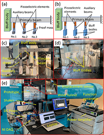
Figure 11. Experimental setup. (a) Schematic of Configuration I; (b) schematic of Configuration II; (c) Configuration II excited under wind excitation only; (d) Configuration II under concurrent wind and base excitations; (e) whole test system.
Download figure:
Standard image High-resolution imageTable 1. Parameters list of the prototype.
| Name | Materials | Parameters |
|---|---|---|
| Primary beam | Aluminium | 178 × 25 × 1 mm3 |
| Auxiliary beam | Aluminium | 110 × 10 × 0.6 mm3 |
| Natural frequency | Primary structure | 9.78 Hz |
| Natural frequency | Auxiliary beam | 12.1 Hz (λ0 = 1.24 as an example) |
| Piezoelectric sheet | MFC2807-P2 | 28 × 7 × 0.3 mm3; CP = 15.11 nF; d31 = −170 pC N−1 |
| Bluff body 1 | Foam | 120 × 36 × 36 mm3; 5.7 g |
| Bluff body 2 | Foam | 50 × 36 × 15 mm3; 0.8 g |
Wind tunnel experiment under pure galloping excitation is first conducted. In figure 12, the performances are compared for three structures: pure primary cantilever structure without auxiliary beams (represented by primary structure only in figure 12), Configuration I aeroelastic metastructure, and Configuration II aeroelastic metastructure (represented by Conf I and Conf II in figure 12, respectively). Experiments are carried out with different values of frequency ratio λ0, which is defined as the ratio of the natural frequency of the auxiliary beam to that of the primary cantilever structure. Figure 12(a) shows the RMS displacement of the bluff body at the free end of the primary cantilever. Galloping suppression firstly improves with the increase of λ0, reaching an optimum at λ0 = 1.24, then degrades when λ0 further increases, showing a similar trend with the theoretical results in figures 4(a) and (b) (note the difference between definitions of λ0 in the experiment and λ in the lumped parameter model). For large values of λ0, such as 6.04 or 7.98, the metastructure prototype fails to attenuate the galloping vibration of the primary structure and even amplifies the vibration amplitude. In the experiment, it is found that the largest amount of power output comes from the auxiliary oscillator at the free end, which is depicted in figure 12(b). Observing figures 12(a) and (b) and simultaneously considering the dual functions of galloping suppression and energy harvesting, Configuration II with auxiliary locally resonating bluff bodies is determined to outperform its Configuration I counterpart by achieving a better balance between the two functions, particularly at the optimal λ0 = 1.24. At this λ0, the galloping displacement of the primary structure is attenuated by 78%, meanwhile a power of 2.63 mW is measured from auxiliary oscillator 1 at a wind speed of 8 m s−1. The time histories of the displacement of the primary structure and voltage from auxiliary oscillator 1, along with the associated FFT spectrums, are illustrated in figure 13, at a wind speed of 7 m s−1 as an example. It is seen that Configuration I successfully reduces the galloping amplitude of the primary structure, where the response remains periodic LCO with a stable amplitude. Configuration II, which includes auxiliary bluff bodies, further mitigates the galloping oscillation by reducing its amplitude. However, due to the added aerodynamic nonlinearity on the auxiliary bluff bodies, there appears extra frequency components, as seen in figure 13(c2), and the oscillation of the system becomes quasi-periodic with an alternating amplitude.
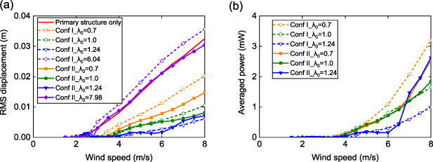
Figure 12. Experimentally measured variations of (a) RMS displacement of bluff body at free end of primary cantilever and (b) average power with wind speed at different λ0.
Download figure:
Standard image High-resolution image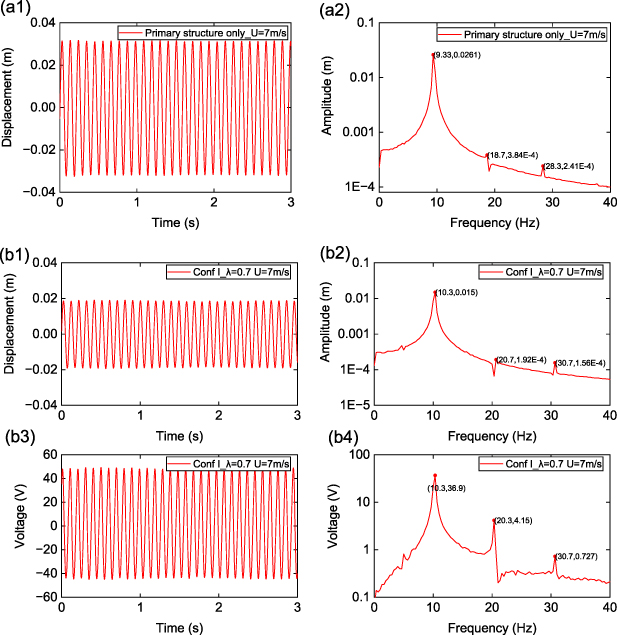
Download figure:
Standard image High-resolution image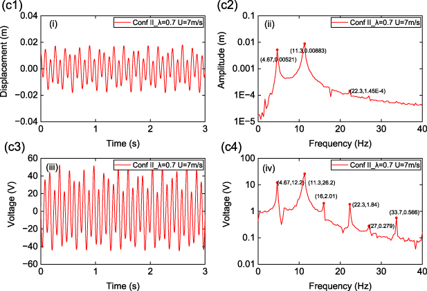
Figure 13. Times histories (left column) and FFT spectrums (right column) of displacement of primary structure and voltage from auxiliary oscillator 1. (a1–a2) Primary cantilever structure only, (b1–b4) Configuration I, and (c1–c4) Configuration II.
Download figure:
Standard image High-resolution imageFocusing on Configuration II, figure 14 explores its performance when the primary cantilever's natural frequency f1 changes. By adjusting the length of the primary beam to modify its natural frequency, it is observed that the percentage of vibration suppression relative to the original galloping response of the corresponding pure primary structure decreases as f1 increases. For example, at 8 m s−1, the RMS galloping displacement is suppressed from 0.0248 m to 0.007 25 m with f1 = 9.8 Hz, while from 0.0142 m to 0.008 32 m with f1 = 16.1 Hz, corresponding to a percentage of suppression of 70.8% and 41.4%, respectively. It is concluded that the aeroelastic metastructure works more effectively when the primary structure is with lower natural frequencies for the purpose of suppressing galloping, although it appears from figure 14(b) that lower f1 is associated with relatively reduced power output.
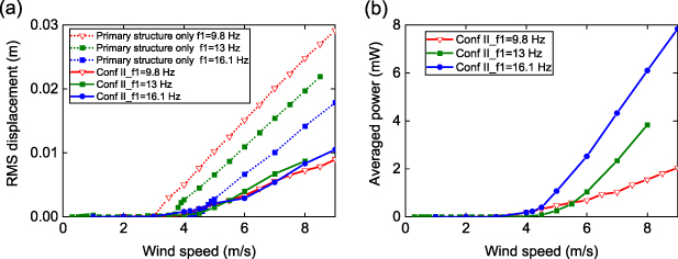
Figure 14. Experimentally measured variation of (a) RMS displacement of bluff body at free end of primary cantilever and (b) average power with wind speed for configuration II at different natural frequencies f1 of the primary cantilever. Average power refers to power from auxiliary oscillator 1.
Download figure:
Standard image High-resolution imageFigure 15 examines the effects of the masses Mbd of bluff bodies on the auxiliary beams in Configuration II on the performance of galloping suppression and power generation. As shown in figure 15(a), the capability of galloping suppression degrades with increasing masses of locally resonating bluff bodies, where the galloping suppression percentage relative to the original response of pure primary structure decreases. Therefore, small Mbd is preferrable for galloping suppression, qualitatively validating the theoretical results in figure 6(b). Again, there is a trade-off between gallloping suppression and energy harvesting, where reducing Mbd enhances the suppression performance but reduces power generation capability, as seen in figure 15(b).
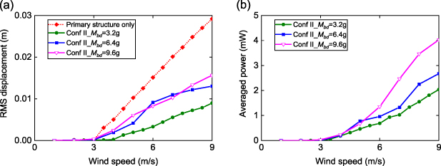
Figure 15. Experimentally measured variation of (a) RMS displacement of bluff body at free end of primary cantilever and (b) average power with wind speed for configuration II with different masses Mbd of bluff bodies on auxiliary beams. Average power refers to power from auxiliary oscillator 1.
Download figure:
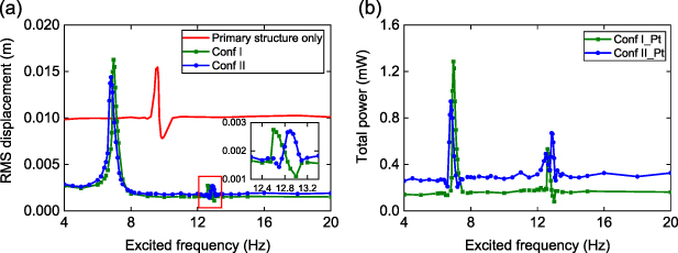
Standard image High-resolution imageExperiments are further conducted under concurrent wind and base excitations for the two aeroelastic metastructure prototypes at a base acceleration of 0.1 g and a wind speed of 5 m s−1, with results shown in figure 16. Both configurations achieve effective vibration suppression with remarkably attenuated RMS displacement, particularly at the off-resonance region. Configuration II also slightly reduces the resonance peak in the first synchronization region. Moreover, Configuration II excels in power generation across the whole considered frequency range, except in the vicinity of its first natural frequency, where Configuration I achieves a higher peak power. Overall, under concurrent wind and base excitations, the Configuration II aeroelastic metastructure with locally resonating bluff bodies is recommended for a better performance in dual functional vibration suppression and energy harvesting.
Figure 16. Experimentally measured variation of (a) RMS displacement of bluff body at free end of primary cantilever and (b) total power with base excitation frequency, at base acceleration of 0.1 g, and wind speed of 5 m s−1. (the total power refers to the power from the sum of oscillator 1, 2, and 3).
Download figure:
Standard image High-resolution image
5. Conclusion
In summary, the proposed aeroelastic metastructure presents a compelling solution for simultaneous suppression of vibrations and energy harvesting under aerodynamic galloping and base excitations. Two distinct configurations are analysed and compared. Configuration I consists of simply regular locally resonating masses subjected to no external forces, while Configuration II includes extra bluff bodies on the locally resonating masses that further experience aerodynamic galloping forces. Piezoelectric electromechanical coupling is inserted to the LRs to enable the mechanical-to-electrical energy conversion. An aero-electro-mechanically coupled model is established based on a lumped parameter finite metastructure chain. Parametric studies are numerically conducted for optimize the performance of the proposed metastructure.
Numerical results show that unlike the widely studied metastructures for preexisting base vibration suppression where the frequency ratio should be approaching 1.0 for optimal vibration suppression, this ratio should be carefully tuned to small values below 0.5 in the two proposed aeroelastic metastructure configurations for effective galloping suppression. Besides, there is a specific optimal mass ratio for Configuration I and II, involving a trade-off between prioritising vibration suppression or energy harvesting functions. In particular, the mass ratio should be kept small in Configuration II to maximize the galloping suppression capability, which is distinctively different from base vibration metastructures where larger mass ratios improves the vibration suppression efficiency. As for effects of electrical parameters, strong coupling favours the galloping suppression capability of Configuration I, but it has minimal influence in Configuration II on the galloping oscillations. Additionally, there exists either one or two optimal load resistance values in Configuration I for ideal galloping suppression and power generation depending on the coupling strength. The galloping suppression capability of Configuration II is unaffected by the load resistance; while for maximizing the power output, the load tuning task is simpler as there is always a single optimal load resistance regardless of the coupling strength. The numerical summary is presented in table 2, providing a guide for selecting parameters when designing a dual-functional aeroelastic metastructure aimed at suppressing galloping vibrations and harvesting wind energy.
Table 2. Parameter selection guideline for the proposed aeroelastic metastructure.
| Parameters | Configuration I | Configuration II | ||||||
|---|---|---|---|---|---|---|---|---|
| Optimal value | Amplitude suppression percentage at ua = 1.82 | Optimal value | Energy harvesting average total power at ua = 1.82 for 3 LRs | Optimal value | Amplitude suppression percentage at ua = 1.82 | Optimal value | Energy harvesting average total power at ua = 1.82 for 3 LRs | |
| Frequency ratio | 0.3 | 40% | 0.2 | 2.45 × 10⁻⁵ | 0.3 | 58.6% | 0.1 | 9.15 × 10⁻⁵ |
| Mass ratio | 1.0 | 95.3% | 0.1 | 5.2 × 10⁻⁵ | 0.2 | 69% | 0.1 | 7.75 × 10⁻³ |
| Load resistance | r = 1.64 (medium value) | 40.9% | r = 1.64 (medium value) | 2.14 × 10⁻⁵ | r = 3.29 (relative larger value) | 58.6% | r = 3.29 (relative larger value) | 5.02 × 10⁻⁵ |
| Coupling | 5 * 7.73 × 10−5 | 98.7% | 2 * 7.73 × 10−5 (medium value) | 4.13 × 10⁻⁵ (for the first LR) | 10 * 7.73 × 10−5 | 59.1% | 10 * 7.73 × 10−5 | 1.07 × 10⁻³ (for the first LR) |
Experimentally, using a fabricated prototype, the galloping displacement of the primary structure is attenuated by 78% with a measured power output of 2.63 mW from a single auxiliary oscillator at λ0 = 1.24 and a wind speed of 8 m s−1. And the results reveal that Configuration II aeroelastic metastructure is favourable with a better performance in the dual functions whatever under pure galloping excitation or concurrent wind and base excitations.
Overall, the theoretical and experimental findings reveal that the proposed aeroelastic metastructure is a promising option for effectively suppressing vibration and capturing energy for systems subjected to wind-induced vibrations or concurrent wind and base excitations. Further optimization of its structural and interface circuit parameters hold potential for enhancing its overall performance in real-world applications.
Acknowledgments
We would like to acknowledge the financial support of the Australian Research Council under Grant No. DE210101382.
Data availability statement
The data cannot be made publicly available upon publication because no suitable repository exists for hosting data in this field of study. The data that support the findings of this study are available upon reasonable request from the authors.