

Abstract
This paper investigates the efficiency of prestressing effect on the flexural performance of reinforced mortar beams through different heating methods. To this end, different specimens reinforced by 1.0% and 1.5% volume fractions crimped shape memory alloy fibers as well as diverse internal and external heating sources are employed. Time-deflection relationships during heating and cooling of specimens are extracted to evaluate the amount of induced prestressing force in each specimen via different heating process. Upon developing prestressing force in the reinforced mortar beams, we carry out several three-point bending tests to study the flexural behavior of mortar beams and compare the material parameters with the reinforced specimens in the absent of prestressing force. The results show that internal heating source using electric current in comparison with external heating via heat gun could be faster and more uniform across the beams cross section contributing to a higher potential capacity in terms of stimulating recovery stress and subsequently boosting ductility and toughness of the composites.
Export citation and abstract BibTeX RIS
1. Introduction
Over the past decades to now several efforts have been conducted for reinforcing cementitious structures using conventional steel fibers through different types of geometries (end-hooked, polygonal twisted, crimped, and so on) [1–4]. Although there may exist some basic diversities in terms of end-forms, methods of productions (continuous or discontinuous), and bond mechanism, all of them provide passive resistance activated with relatively large deformation [5–8]. In cementitious materials tensile cracking strains are so small. Thus, the conventional fibers even could not be able to generate active resistance in mortars or concretes. They are only capable to increase post-cracking strength and ductility of the matrix [9–12]. However, the active resistance of shape memory alloy (SMA) fibers acting as a prestressing effect, can increase tensile strength of the cementitious materials [12].
In recent years, smart fibers consist of SMAs have been widely used in reinforcing such materials due to their unique properties of shape memory effect (SME) [13–18] and superelasticity (SE) [19–23]. Also, a recent state-of-art study [24, 25] illustrates applications of SMAs for infrastructures including recent practical applications as well as research needs in future. To develop recovery stress stemmed from SME, fibers should initially be elongated before embedding in a matrix, and then, it can be activated by increasing temperature and subsequently stimulates phase transformation which results in inducing prestressing effect on concretes; this process may provide cracking resistance for very small tensile cracks even before loading [24, 25]. It is completely well-known that SMA elements are required to receive pre-strain via two possible techniques including direct tensioning method which seems to be tedious and ineffective method as well as cold drawing to admit pre-strain [26, 27]. Cold-drawn SMA wires showing totally different mechanical behavior in tension than as-received wires, however, still produce high recovery stress beside being effective for mass production; thus, cold drawing may be an appropriate candidate for imposing pre-strain in SMA elements [28–30].
Furthermore, providing enough bond resistance when embedded in composites can be considered another crucial factor in choosing such reinforcements. Several researches have proven that among a diversity of the geometries [31] crimped SMA fiber may show higher bond strength as long as a controlled wave depth and fiber's length are chosen [32, 33]. Khodadadi et al reported that crimped SMA fiber should relatively have small wave depth compared with crimped steel fibers to provide an appropriate bond resistance in mortars [33]. Generally, crimped steel fiber provides bond resistance and energy dissipation due to plastic deformation at bent parts. However, if crimped SMA fibers have such a large wave depth to steel fibers, they may not generate recovery stress because stretching parts of waves may overcome and finally neutralize induced recovery stress through phase transformation [34].
In order to activate SME and then recovery stress, heat gun (HG) or electric heating or current (EH) can be used to elevate the SMA element's temperature. In the case of heat gun, hot air increases mortar temperature, and then, the temperature transfers to the SMA fibers. Electric current may also heat up the steel wire's, subsequently, it rises the temperature of SMA fibers located around the steel wires [35].
Several tries have been conducted for maximize activation of prestressing effect in terms of optimized shape; Choi et al [35] applied dog-bond shaped SMA fibers to introduce prestressing effect in reinforced mortar beams, and HG was used to increase temperature of the SMA fibers inside mortar. In that case, the surface temperature was gauged about 300°C, while inside temperature was relatively low about 146°C; the beam length of 160 mm was very short and a HG was enough to heat the middle part and to activate the SMA fibers. However, if the beam is long, then several guns would be necessary for heating at the same time, or they should move from one side to another side. Li et al conducted flexural tests of concrete beams reinforced with NiTi SMA wires with 2 mm diameter, which were elongated by 8% strain before embedded in concrete beams [36, 37]. After crack initiation, the SMA wires were heated by EH and induced recovery stress resulting in reducing crack opening points. Recently, several researchers have used electric current to heat the crimped SMA wire embedded in mortar beams [38, 39]. In the test, the crimped SMA wire provided prestressing on mortar beams and showed great self-centering capacity during the cyclic bending tests, which was almost equal to that of the superelastic SMA wire. The lengths of the beams were 500 mm and 300 mm for Li et al [37] and Choi's tests [38], respectively and for applying electric current, the SMA wire were placed from one end to another end, while long fibers may have more convenience to heat, several benefits of reinforcing may be lost; thus, short fibers distributed in matrix have been suggested by numerous researchers [11, 40].
Most of concrete or mortar beams reinforced by randomly distributed or organized short SMA fibers or strips are under bending stresses [41–43], so inducing prestressing effect through different heating methods is of considerable importance during flexural behavior. In the case, the electric current cannot be applied directly on the fibers and HG may not be efficient if the beam is long; thus, in this study electric wires have been placed inside a mortar to generate recovery stress stemmed from SMA fibers. To this end, it is planned to investigate the efficiency of prestressing effect through an electric current as well as a HG for randomly distributed SMA fibers in mortar beams. Initially, crimped SMA fibers with different volume fractions of 1.0% and 1.5% along with several electronic wires for imposing internal heating are embedded in mortar beams. Then to investigate recovery stress and prestressing force in reinforced specimens, deflection of beams during thermal process is measured based on consumed time. After developing prestressing effect, several three-point bending tests are conducted to figure out the influence of prestressing effect on the flexural behavior of mortar beams. Using thermal as well as digital image correlation (DIC) cameras, we could observe the process of heating and crack propagation during bending tests. This paper is organized as follows. In section 2, the geometry and the material parameters of SMA fibers and the process of preparing mortar beams as well as experimental setup are presented. Section 3 describes the relationship between time and temperature of reinforced beams at different points using thermocouples and thermal camera; then to distinguish the efficiency of the internal or the external thermal stimuli in generating prestressing effect, we measure time-deflection relationship via diverse methods of heating. Flexural behavior of the reinforced mortar beams with and without inducing prestressing force are investigated in section 4. Moreover, crack analysis during the bending tests is monitored and compared using DIC technique. In section 5, we finally draw conclusions.
2. Specimens
2.1. Geometry and material parameters of Ni-Ti fibers
In this section, rather than a direct tensioning method we initially imposed pre-straining on Ni50.4‐Ti (wt.%) wires via the cold drawn technique. A vacuum induction melting SMA ingot was hot rolled and then the wire diameter might be reached 1.0 mm, then again it was reached 0.81 mm by cold drawing and prepared via annealing with 450°C for one hour. Austenite starting (AS) and finishing (AF) temperatures can be extracted from differential scanning calorimeter (DSC, the device is DSC25 of TA instrument) test which are 48.05°C and 110.16°C, respectively (figure 1).
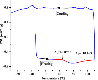
Figure 1. DSC curve for the SMA wire during cooling and heating.
Download figure:
Standard image High-resolution imageMotivated by several benefits of wire crimping in terms of inducing prestressing effect [38–41], in this study a crimped wire is chopped to form several short fibers. Initially, the wire continuously is indented via a rolling device with a pair of 128 teeth gears to achieve a crimped wire with the height of 0.89 mm (figure 2). Finally, the crimped wire is cut to manufacture 30 mm fibers in length. As represented in table 1, different fibers heights are tested to figure out the residual and recovery stresses at 300°C. Constraining the fibers at 25°C, the attributed recovery stress to the SME feature was gauged as the fibers heated up to 300°C. Thus, the SMA wire is custom ordered, and not commercial one; however, the process of crimping the fibers has been done by this group.
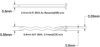
Figure 2. Geometry of a crimped fiber.
Download figure:
Standard image High-resolution imageTable 1. Different heights of CR fibers.
| Fibers | CR-1 | CR-2 | CR-3 | CR-4 |
|---|---|---|---|---|
| Height (mm) | 0.8343 | 0.8505 | 0.8910 | 0.9315 |
For the CR-1, CR-2, CR-3, and CR-4 fibers, the maximum recovery stress reached the level of 253, 225, 208, and 165 MPa, respectively (figure 3). To read the residual stresses, if the temperature cools down to 25°C, they might be 201, 196, 193, and 166 MPa, respectively. Regarding the results in figure 3, except CR-4 fiber with the residual stress of 166 MPa, whole fibers achieved 200 MPa. Moreover, it was proved that among all of the fibers, the CR-3 fiber could reveal the best bond resistance behavior without yielding upon pulling out test [32]. Therefore, the best candidate to reinforce mortar beams is the CR-3 fiber due to better bond behavior as well as less the stress changes upon switching from recovery to residual stresses. The bulging percentage for the fibers are represented in table 2, although these relative variations are less than 1%, this effect can contribute to delaying microcracks initiation [40].

Figure 3. Heating and cooling the constrained fibers to read recovery and residual stresses.
Download figure:
Standard image High-resolution imageTable 2. The values of fiber diameter and bulging percentage.
| Type of fibers | CR_L20 | CR(H)_L20 | CR_L30 | CR(H)_L30 | CR_L40 | CR(H)_L40 |
|---|---|---|---|---|---|---|
| Diameter (mm) | 0.809 | 0.812 | 0.808 | 0.812 | 0.807 | 0.812 |
| Bulging (%) | 0.37% | 0.49% | 0.62% | |||
2.2. Reinforced and unreinforced rectangular mortar specimens
Mixing mortar compositions including Type I Portland cement (37.7%), fly ash (5.6%), silica sand (37.7%), and water (19%), several reinforced and unreinforced rectangular mortar specimens with a length and dimensions of 400 and 50 × 50 mm, respectively, are cast. Two types of the reinforced mortar beams are prepared with different volume fractions: 1% and 1.5% of crimped SMA fibers. For reinforcing the specimens, we randomly add the crimped fibers (CR) to the mortar and only mold the lower half of the beams. Then immediately the molds are filled with plain mortar at the remain upper part. This process may save the SMA fibers at the lower part to induce prestressing in where seems to be a critical region for flexural behavior. Upon 24 h casting, we demold and then cure the specimens for about one month in a water bath with the temperature of 23 ± 2°C. In order for providing uniform heat transfer to the fibers, a set of organized A2 stainless steel wires as shown in figure 4, are embedded in the mortar which could assist to induce uniform recovery stress or prestressing effect as well and can also play a significant role in the reinforcements.
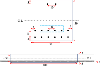
Figure 4. Dimensions of beams and position of A2 stainless steel wires lain in the mortar beams (mm).
Download figure:
Standard image High-resolution imageTo distinguish the required numbers and positions of the steel wires to trigger off with a controllable voltage source, several tried-and-tested methods may be conducted (figure 5) while the voltage is increased from 0 to 12 V in about 8 s. Moreover, the critical deflection due to the thermal expansion is determined where no fracture could be seen in the beams upon heating. At initial tried-and-tested method for a plain mortar beam, the current flows through all steel wires, however, after reaching the temperature 130°C at the bottom side, the beam starts having a sudden deflection (figure 6(a)) and eventually failed at about 0.5 mm (figure 6(c)). The second tried-and-tested experiment is conducted while we reduce the number of steel wires from 12 to 8 but for the reinforced specimens with 1.5% volume fraction (figure 6(b)). The results corresponding to this test is depicted in figure 6(c); at the temperature of 160°C the downward deflection failure is about 0.8 mm. Therefore, based on these two tests we decide to again reduce the number of heated steel wires to four in the second row (blue dots, figure 4) and also consider the critical downward deflection for the reinforced beams at about 0.5 mm.
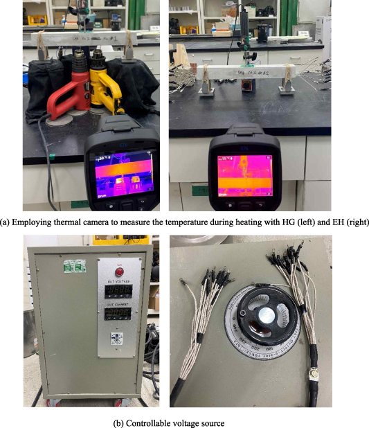
Figure 5. Inducing prestressing effect through different heating methods.
Download figure:
Standard image High-resolution image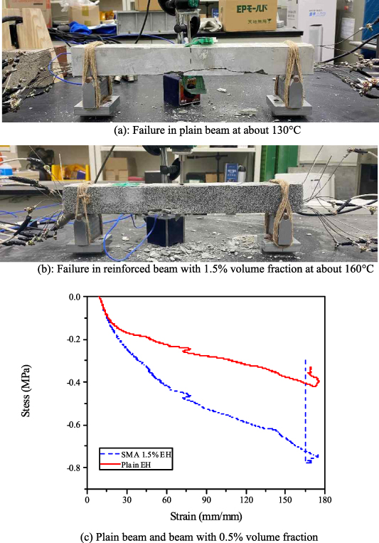
Figure 6. Tried and tested methods considering deflection versus temperature.
Download figure:
Standard image High-resolution image3. Act of recovery stress as a prestressing effect in the mortar beams
3.1. Relationship between temperature, deflection and time
In order to activate recovery stress stemmed from phase transformation process in the SMA fibers distributed in the lower half of the specimens, we introduce different heat sources: HG and controllable voltage source (figure 5). Since the HG can only be employed in emitting a stream of hot air locally, we also use the controllable voltage source for more uniform thermal distribution to generate recovery stress. In the former method, the HG temperature is adjusted to 300°C, and placed at the middle of the beam along with an linear voltage displacement transducer (LVDT) on the opposite side to read the beam deflection during heating and cooling process. Moreover, to gauge the thermal variations a thermocouple and thermographic camera using infrared radiation were employed to capture and analyze the temperature data throughout the length of specimens. Figure 7(a) illustrates variation of the temperature versus consumed time upon heating and cooling at three positions of bottom, middle and top surfaces of a 1% volume fraction reinforced beam. Temperature is sharply elevated from ambient to 200°C in about 750 s where the steel fibers are lain at the bottom side. Highest temperature at the middle and top of the specimens where there is an offset from the embedded fibers reached about 80°C and 60°C, in about 900 s and 1300 s, respectively. Due to this offset, there is a substantial difference in the elevation of the temperature for middle and top positions and a delay to gradually reach their highest temperatures when compared to the bottom surface. However, the bottom side steeply starts losing its heat, the other sides may have a gradual reduction and eventually, the beam cooled down and each side's temperature is converged to the same value at about 50°C.
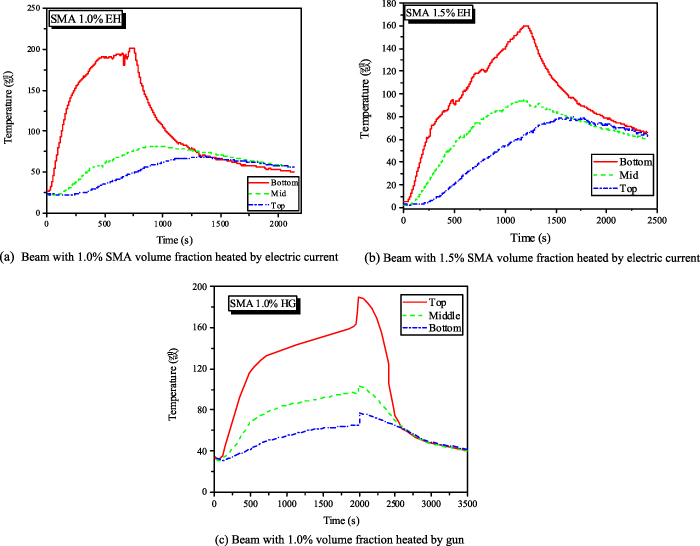
Figure 7. Temperature variation during heating and cooling for different types of specimens.
Download figure:
Standard image High-resolution imageSimilar behavior also occurs in the reinforced beam with 1.5% volume fractions when using electric current (figure 7(b)), whereas temperature variation for the specimens heated by a gun obeyed different trend due to the non-uniform temperature gradient as well as temperature rise time for different parts of the beam. The maximum temperatures are 200°C, 100°C and 75°C, at bottom, middle and top sides while in contrast to EH beam no delay could be seen when achieving their highest temperature via the heat gun.
Figure 8 shows time-deflection relationship via diverse methods of heating for the mortar beams reinforced with different volume fractions. For all types of specimens and heat sources, when the temperature elevated from 25°C, the downward defection promptly appears in the beams for the sake of thermal expansion stemmed from thermal gradient. Their maximum deflection might be reached at −0.5 mm for EH and −0.45 mm for HG. Deflection lingered on these values until the heating is stopped at 750 s, 1250 s and 2000 s for 1%-EH, 1.5%-EH, and HG, respectively. Tacking more time in this part through HG in comparison with other graphs can be attributed to locally imposed heating via this method. However, upon elimination of heat sources, the beam deflection almost aggressively does a U-turn to upward and achieves its maximum value at about 0.3 mm for specimens with 1% and 1.5% SMA fibers volume fractions whereas for the HG it reaches about 0.1 mm. This process could activate SME in fibers, but due to the given constraints on their movements in the mortar beams, this feature may produce recovery stresses inducing prestressing effect to control and put off crack propagation. Comparing point 6 for both EH and HG, the influence of heating methods on prestressing effect is crystal-clear so that the developed deflection seems to be about three times higher than the HG showing appropriate efficiency of the EH.

Figure 8. Displacement versus time for different types of specimens and heating methods.
Download figure:
Standard image High-resolution imageFurthermore, temperature distribution and variation during heating and cooling down the fibers using thermal camera are illustrated in figures 9 and 10. Considering the constant points at different locations from bottom to top (SP1, SP2, and SP3), we can describe the history of temperature variation through entire of the specimens heated by EH and HG for points 1–6 shown in figures 9 and 10. According to these points, distribution of the temperature along the length when the electric heat is applied might regularly change layer by layer and finally at point 5 onwards almost uniform distribution occurs across the cross sections. In contrast to EH, upon heating the specimens via HG, temperature initially starts to elevate at some specific areas near to the flames and then gradually permeates into the rest of the beam. This heat concertation could be a double-edged sword, less adverse effect for the matrix but also less capacity to induce prestressing effect in that mortar. However, the electric current can produce uniform heat flux throughout the beam, this process is relatively fast so that temperature controlling seems to be hard to some extent, beside crack initiation and fibers bulging would suddenly occur sooner when compared to the heat gun.
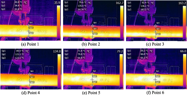
Figure 9. History of the temperature gradient in the beam heated by EH captured by thermal camera.
Download figure:
Standard image High-resolution image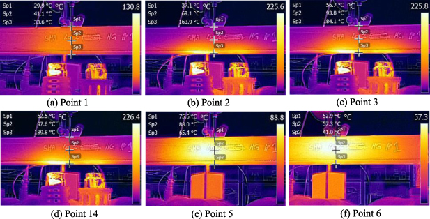
Figure 10. History of the temperature gradient in the beam heated by HG captured by thermal camera.
Download figure:
Standard image High-resolution image3.2. Prestressing force assessment
Residual stresses can be induced in the SMA elements at the end of heating step or stable condition (point 6); thus, equation (1) has been considered to achieve prestressing force for a heated reinforced beam under simply supported ends
In that expression P and Δ denote, respectively, prestressing force and beam deflection. Moreover, lef, e, and EcI respectively, represent the effective beam length, eccentricity of the SMA fibers from centroid and the flexural rigidity of the reinforced beam. Considering table 3 and Young's modulus of the electronic steel wires Es (figure 11) as well as calculating moment of inertia and employing the diagrams of time-displacement in figure 8 for each three mortar beams for obtaining Δ, the prestressing force is determined in figure 12. The highest generated force (27.8 kN) belongs to 1% volume fraction reinforced beam when heated by electric current and the lowest amount of this stress (10.0 kN) takes place at this type of reinforced beam showing about 64% reduction upon choosing a local heating method. This method can only concentrate on a specific point of the beam while recovery stress may not be activated throughout the mortar. However, in the second case with 1.5% volume fraction there would be 50% rise in the amount of employed SMA fibers, 13% decrease occurs in the prestressing force due to this volume fraction increase; therefore, the adverse effect of too many fibers embedded in the mortar cannot be deniable.
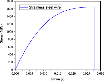
Figure 11. Stress–strain curve of steel wires.
Download figure:
Standard image High-resolution image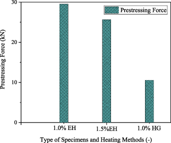
Figure 12. Generated prestressing force in different type of volume fraction and heating methods.
Download figure:
Standard image High-resolution imageTable 3. Material parameters for the reinforced beams.
| Ec | Es | I | e | lef |
|---|---|---|---|---|
| 30 GPa | 150 GPa | 535 623 mm4 | 16 mm | 340 mm |
4. Three-point bending tests
4.1. Test setup
A servohydraulic testing machine having a capacity of 20 kN is monotonically used to carry out three-point bending tests via a system of displacement control under a speed of 1 mm min−1. To conduct three-point bending test, the supporting points are set to have a span of 360 mm, and one LVDT is well positioned at the middle of the beam to measure the vertical deflection (figure 13(a)). Moreover, a 2D-DIC system along with a data acquisition device and a light emitting diode (LED) light source are employed to observe crack initiation and gauge the strain on the surface of mortar beams (figure 13(b)). Finally, through a scanning system of x-ray computed tomography (CT), real position and distribution of fibers technically become feasible (figure 13(c))
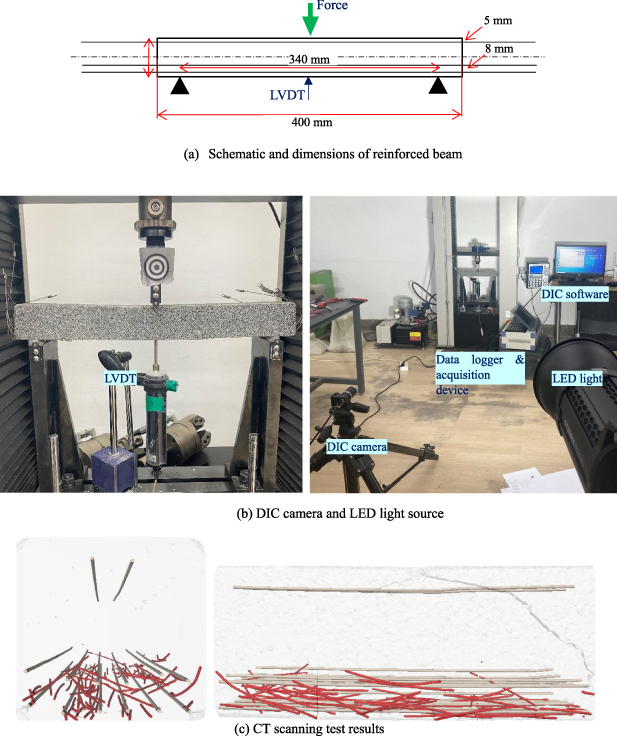
Figure 13. Experimental test setup and measuring instruments.
Download figure:
Standard image High-resolution imageLoad and displacement response of the reinforced mortar beams under three-point bending tests are depicted in this section. Figure 14 indicates the effect of volume fraction on flexural behavior of the reinforced mortar beams with SMA fibers, although the effect of recovery stress is not included at this graph. The initial stiffness of the plain material is perfectly same as other reinforced specimens, however when it comes to crack initiation point, the plain mortar slightly shows better response than the specimen with 1.5% volume fraction whereas for the beam with 1% volume fraction, the corresponding load significantly is higher than other specimens about 2 kN. Due to the propagation of several cracks, there is a considerable reduction in the material stiffness and softening region may be emerged in all of the specimens. It is clear that the beam with 1% volume fraction has approximately 20% and 28% higher maximum load capacity in this region than that of plain and 1.5% reinforced specimen, respectively. The maximum load bearing for 1% volume fraction reinforced beam occurs at the deflection of 2.5 mm and about 4.8 kN, while the figure for another case is almost about 3.7 kN at the fracture deflection of 5 mm. Although the maximum load capacity is increased for 1.0% volume fraction, the material ductility initially has reduced and then found its original value at 1.5% volume fraction. The experimental data proves that the amount of volume fraction affects the property of the mortar so that increasing the volume fraction from 1% to 1.5% has improved the ductility however at the same time reduced maximum load bearing; thus, in the absent of inducing prestressing force the absorbed energy in plain, 1.0% and 1.5% volume fraction may read 14.4 J, 17.5 J and 18.7 J, respectively. However, in order to judge the performance of the prestressed beam under flexural behavior we will continue our study by initially inducing prestressing effect via the EH and subsequently performing three-point bending test.
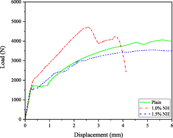
Figure 14. Load versus deflection under three-point bending test and without activation of SME.
Download figure:
Standard image High-resolution imageSince in real environment, temperature control process to induce prestressing effect in RC beams via electric current would be to some extent laborious, in this study we intend to impose a relatively high temperature in the samples. Therefore, to evaluate the effect of setting a very high temperature in SMA fibers and subsequently its induced recovery stress on the matrix, figure 15(a) compares load-deflection of the non-heated (NH) mortar beams with the specimens at the same volume fraction of 1%, which are initially heated using the EH and then exposed to three-point bending tests. As a result of provoking a very high temperature in the mortar via EH, flexural rigidity of the beam is reduced considerably about 25%, while crack initiation starts at a higher displacement about 12% to that of NH case, in addition load bearing capacity is shifted from 2.5 mm and 4 kN to deflection and force of 4 mm and 5.2 kN, respectively. After initiation of cracks a smoother softening region can be seen in load-defection response of the heated cases when compared to the NH specimens. Furthermore, in terms of energy absorption, prestressing effect stemmed from the SMA fibers could increase the toughness of the material about 63%. In figure 15(b), the load and deflection response for the mortar beam reinforced with 1.5% volume fraction indicates similar trend towards the specimen with 1% volume fraction in terms of a reduction in stiffness 25% and an increase in toughness 7.5% through the heating process. As it is clear, imposing high temperature in this beam even with a higher volume fraction does not change mortar's stiffness.
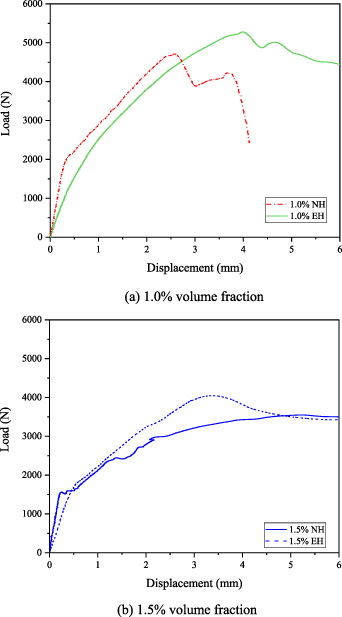
Figure 15. Load versus deflection under three-point bending test and with activation of SME.
Download figure:
Standard image High-resolution imageFinally, to distinguish which volume fractions may obtain the best flexural performance upon inducing prestressing effect, figure 16 has compared load-deflection relationship for the 1.0% and 1.5% volume fractions. It shows that rising the temperature and subsequently generating recovery force can significantly boost better the bending behavior of 1.0% than 1.5% volume fraction. Therefore, in spite of having lower ductility in comparison with 1.5% in figure 14, upon imposing temperature, 1.0% volume fraction could maintain both higher maximum loads bearing capacity as well as ductility leading to a better efficiency through possessing higher material toughness about 25%.

Figure 16. Load versus deflection response and with activation of SME for both 1.0% and 1.5% volume fractions under three-point bending test.
Download figure:
Standard image High-resolution image4.2. Crack analysis
Effect of induced prestressing force on the mortar beams can be discussed in both terms of surface cracking as well as cracking patterns. The cracking patterns upon three-point bending test for the plain, heated and NH reinforced beam with the 1% volume fraction are illustrated in figure 17. Internal microcracks are formed once the bending stress is exceeded the strength of the mortar in all of the specimens, however in the plain case the main crack could easily propagate so that flexural cracking occurs at the middle of the beam, which is the largest point of bending moment. In the NH case, the electronic wires acted like reinforcement, and, thus, cracking starts at the quarter point and diagonal cracking is dominant, which is typical flexural failure for the reinforced mortar beams. However, angles of the cracking at the bottom and middle parts are different so that in the middle, the cracking angle is vertical (figure 17(b)); this is the same as that of the plain mortar beam. The SMA fibers in the NH case act like conventional reinforcement since they are placed continuously along the length of the beam. In the heated case, cracking pattern is almost same as that of the NH case. The difference is angle of cracking at the middle part; the angle of the middle part is diagonal (figure 17(c)). Therefore, it seems that the change in the angle is attributed to the prestressing effect of SMA fibers. Since on the overall apparent looking, it is not distinguishable between the two cracking patterns, we use DIC equipment to analyze surface cracks.
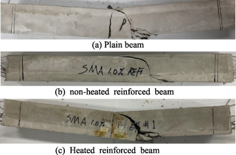
Figure 17. Fracture modes for different types of the mortar beams.
Download figure:
Standard image High-resolution imageIn figure 18, two types of heated and NH mortar beams reinforced by the 1% volume fraction crimped SMA fibers are considered. The longitudinal strain as a color map superimposed on the mortar surface evaluates the effect of induced prestressing forced on the bending response of the beams. In the left column the specimen is not heated and then exposed to transverse loading; thus, only the effect of reinforcing may be considered. The trend of cracks propagation according to figure 18(a1)–(a5) shows that microcracking begins at the middle part and then other cracks are developed to supporting sides due to the stress redistribution; this cracking pattern is typical in the reinforced mortar beams. The main cracking is developed at the quarter point (the red region in figure 18(a5)), which starts diagonally and changes to vertical. Thus, the shape of cracking pattern is exactly same as that in figure 17(b), apparent final cracking.

Figure 18. Comparison between the strain contour for heated and non-heated specimens under three-point bending test via DIC camera.
Download figure:
Standard image High-resolution image
On the other side, prestressing effect is imposed on the mortar due to the stimulation of phase transformation in the SMA wires through electric current causing to increase the material toughness. Critical differences of cracking pattern in the heated beam are (a) wide microcracking strain area and (b) only three main cracks developed. Thus, it can be conjectured that the prestressing prevents stress redistribution. In the NH case, stress concentration occurs at the crack tip, and, thus, the crack propagates along with narrow area. However, in the heated case, the stress concentration at crack tip might be reduced due to the prestressing effect. Finally, the main cracking (red region in figure 18(b5)) is diagonal, which is different from the previous one (figure 18(a5)). Furthermore, comparing the DIC data of each sides shows that the intense of generated tensile strain is reduced about 13% due to the effect of recovery stress in SMA fibers.
5. Summary and Conclusions
In the present study, considering the reinforced mortar beams with different volume fractions of the crimped SMA fibers (1.0% and 1.5%) as well as diverse internal (EH) and external (HG) heating methods, the workability of prestressing force on the performance of these beams during bending behavior is evaluated. Initially, time versus deflection during heating and cooling down the specimens is extracted, showing the larger capacity of the EH in generating upward deflection. Due to the better performance of the EH in activating prestressing force, we tried to elevate the fibers temperature in the mortar beams with different volume fractions and subsequently compare the material parameters under the flexural behavior. Using thermal camera and DIC equipment we could also track temperature gradient as well as crack propagation during the three-point bending test.
Upon inducing prestressing effect by different heating methods, it is found that the upward deflection created in the specimens are about .03 mm and for that of HG it takes about 0.1 mm. Although the same generated upward deflection in 1.0% and 1.5% volume fractions are shown in figure 8, it should be mentioned that according to figure 12 the amount of prestressing force in the latter is 14% less than that of the former. Two other important factors in choosing a better heating method can be the rapidity as well as the uniformity of the process. Figure 6 proves that not only the HG is averagely 34%, time consumer than the EH, but also the upward deflection is significantly lower than EH. Upon rising the temperature through EH, we also could see very uniform heat distribution in each layer of the matrix while via local heating only some parts of the beams are exposed to generating recovery stress meaning that this process may fail in activating the fiber's prestressing force. Moreover, reinforcing the mortar beams with 1.0% and 1.5% volume fraction illustrates that due to the bridging effect crack propagation starts with an appropriate delay in the composite, however, 25% reduction happens in the maximum load bearing capacity through 1.5% volume fraction, the material toughness is increased about 45% (figure 14). Upon stimulating recovery stress in both samples, we found that this force might be acted very effectively for 1.0% volume fraction than 1.5% through the EH so that 12% and 51% higher load bearing capacity and energy absorption takes place in the three-point bending test, respectively. We figure out that too much increase in the volume fraction and then heating may have some more intensive side effects on the bending response of the beam during flexural behavior. Although the beam stiffness may adversely reduce through heating, it seems that detrimental effect of increasing the volume fraction would surpass the damaging impact of imposing high temperature. Our experimental data yielded following findings:
- Upon heating the reinforced beams and by removing the heat, initial downward deflection due to thermal expansion as well as a sudden upward deflection because of generated recovery stress can be observed, respectively. The recovery stress acting as a prestressing force in the mortars becomes gradually stable.
- The prestressing force caused by the EH indicates triple upward deflection when compared with the HG; and the measured prestressing force in the former is 2.8 times higher than the latter.
- Rapidity and uniformity of heating as well as capability of inducing recovery stress in all distributed fibers through the EH are significantly more efficacious than locally heating via the HG.
- Before heating, the maximum bearing load and toughness in the reinforced beam with 1.0% volume fraction was 28% and 21% higher and less than 1.5% volume fraction, respectively. While after inducing prestressing effect, these numbers for 1.0% volume fraction were shifted to 23% and 18% higher than 1.5% case.
- Employing the electric current might reduce the flexural rigidity of the composites about 25%, while a considerable decrease is seen in the stiffness but still the detrimental effect of heating could be ignored due to a significant boost for load bearing capacity, ductility as well as delaying in crack propagation.
- The introduced prestressing force to the mortar could dissipate crack energy so that 11 main cracks created in the absent of recovery stress are reduced to only three main cracks, and subsequently might postpone propagating the cracks while increasing the material toughness.
- The cracking pattern in non-reinforced area starts propagating vertically similar to the plain mortar, however, due to the prestressing effect in the heated specimens, these non-reinforced areas may act like the reinforced beams and diagonal cracking pattern can be seen.
The specimens in this study are relatively small, while the SMA fibers are mixed based on volumetric fraction. Thus, if the same volumetric fraction will be used for real members of structures, the same effects could be expected.
Acknowledgments
This work was supported by a grant from the National Research Foundation of Korea (NRF) funded by the Korean government (MEST) (Project No. NRF 2020R1A4A-1018826).
Data availability statement
No new data were created or analysed in this study.