

Abstract
Piezoelectric transducers which rely on oscillating cantilever-type beams to harvest mechanical energy locally available in environments have been of great interest as a substitute for batteries. Most of the research efforts focus mostly on designs which aim at resonance matching to achieve maximum energy output without taking the mechanical degradation of the piezoelectric layers into consideration. The purpose of this study is to propose an energy harvesting design which maximizes power output on the long run. Unimorph cantilevers, in which the neutral axis is located at the interface between the soft lead zirconium titanate (PZT) (PZT5A4) layer and the inert substrate (Pernifer 45), are used. An analytical model is developed to quantify the performance of the harvesters as a function of free length and tip mass. An experiment is set up to validate the theoretical model. To reduce the occurrence of cracks induced in the piezoelectric element due to the cyclic nature of the vibrational excitation, a housing acting as mechanical stroke limiter is adopted. The effect of the single-side stroke limiter on the power output and lifetime of the cantilevers is investigated. A 40 mm free length unimorph cantilever with 300 mg mass attached on the tip exhibiting an 18% increase in power output (0.1 mW) is proposed. An improved lifespan of the cantilevers is obtained by limiting the tensile deformation of the piezoelectric layer. This study opens the opportunity for more effective energy harvesting mainly through compressive operation for longer periods.
Export citation and abstract BibTeX RIS

Original content from this work may be used under the terms of the Creative Commons Attribution 4.0 license. Any further distribution of this work must maintain attribution to the author(s) and the title of the work, journal citation and DOI.
1. Introduction
The increased demand for electronics, such as wireless sensors and health monitoring devices, in the coming era of the Internet of things (IoT) has raised urgent requirements for portable and sustainable power [1, 2]. Continuous advances in electronics technology allow the ongoing decreasing size of integrated circuits while batteries have not experienced the same rate of miniaturisation. Batteries, therefore, remain the largest and heaviest component of the entire unit [3]. Furthermore, their limited lifespan and the necessity for periodic charging are a few more reasons that have led research efforts to alternative power supplies [4, 5]. Powering IoT devices using parasitic energy locally available in environments such as industrial machines, human body, structures, and vehicles has been an attractive solution. Environmental mechanical energy represents one of the richest ambient sources. To scavenge this form of energy, electromagnetic induction, piezoelectricity and triboelectricity have been proposed as energy harvesting approaches [6]. Among them, piezoelectricity is at the front of scientific research due to its high energy density at low-scales, ease of integration and miniaturization [7].
Cantilever-type energy harvesters with one or two active layers (unimorph or bimorph) located on a vibrating host structure are the most utilized piezoelectric transducers which generate electrical energy from base excitations [8, 9]. Brittle ceramics, such as lead zirconium titanate (PZT), are usually used as piezoelectric material due to their high electromechanical coupling coefficient [10]. Piezoelectric beams generate significant energy output when they are excited at resonance [11]. However, such harvesters are not effective when there are small fluctuations in the ambient vibration frequency due to their relatively narrow operational bandwidth [12]. With regard to this issue, several approaches that allow frequency tuning have been proposed, such as monostable and bistable [13–16], multi-cantilever structures [13], passive and active stiffness-tuning technologies [17].
Most of the research efforts focus on optimising energy harvesters to achieve maximum energy output without taking their long term stability into consideration [18]. Piezoelectric energy harvesters are intended to replace batteries since they can theoretically offer power for unlimited time, thus making the lifetime one of the most essential properties to end users. However, one can notice that this issue has seldom been addressed in the literature. The cyclic nature of the vibrational excitation, the non-uniform strain distribution along the length of the beam and the addition of a large proof mass on the tip are some of the reasons that make the mechanical degradation of the piezoelectric layers inevitable [19, 20].
From the perspective of applications, the insufficient power output, narrow operational bandwidth, and limited lifetime due to cyclic fatigue are the main barriers that prevent cantilever-type energy harvesters from being widely adopted in engineering practice. In this paper, a unimorph cantilever-based energy harvesting design which addresses these three metrics simultaneously is reported. A single-side stroke limiter is adopted allowing asymmetric deflection. The influence of the resulting boundary conditions on the generated power at various distances between the stroke limiter and the beam, is explored. The resonance frequency of the unimorphs as a function of the free length and tip mass and the operational bandwidth through different impact stages are studied. The variation of the unimorphs lifetime is explored by limiting either the compressive or tensile bending movement and the results are compared. This study provides guidance in designing piezoelectric energy harvesters and opens the opportunity for more effective energy harvesting for longer period mainly through compressive operation.
2. Experimental
2.1. Preparation of piezoelectric unimorphs
In this study, unimorph cantilevers were fabricated. Soft PZT (PZT-5A) with a Young's modulus of 69 GPa was selected as piezoelectric material. Pernifer 45 with a Young's modulus of 193 GPa and thermal expansion coefficient similar to the piezoelectric material was used as a passive substrate layer. The two layers were glued together using epoxy (302-3M) blended with 5 wt% nickel balls to create a conductive path and then cured at 700 °C for 3 h. The thickness of the adhesive layer was adjusted so that the neutral axis of the unimorph was located at the interface between the active and the passive layer. A thin layer of carbon paste (DuPont 7102) acting as electrode was fabricated on the top of the PZT layer by doctor-blading. To induce the piezoelectric activity, the unimorph cantilevers were subjected to contact poling where a high electric potential of 500 V (2 kV mm−1) was applied in the thickness direction for 10 min. The width and total thickness of the unimorphs were fixed at 5 and 0.45 mm, respectively. Three different free lengths were tested; 20, 30 and 40 mm. As for proof mass, steel foil attached at the free end of the cantilever was used. The number of stacked pieces of steel foil defined the weight of the tip mass.
2.2. Harvester configuration
To reduce or even better to avoid the occurrence of cracks in the piezoelectric element due to large oscillations, a stroke-limiting casing was adopted (figure 1). The cases were made of acrylonitrile butadiene styrene by 3D printing. The casing was designed to limit only the upwards bending movement of the unimorphs. When the unimorphs bend downwards, they are free to move. The dimensions of the casing were optimized depending on the estimated tip mass deflection under controlled non-resonant excitation conditions and the free length of the unimorph cantilevers. To study the effect of different strokes H, a screw (ISO metric, M3) located at the end of the case was used as stroke limiter. H is defined as the distance between the bottom part of the stroke limiter and the upper surface of the unimorph cantilever or the tip mass when exists. The unimorph can be clamped such that the piezoelectric layer is the top or the bottom layer. The tip mass is always on top.
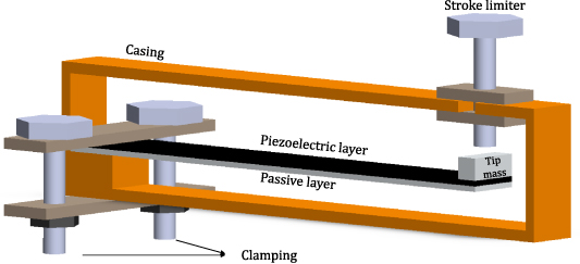
Figure 1. Schematic drawing of the harvester placed inside the deflection-limiting casing. The unimorph can be inverted such that the piezoelectric layer is the bottom layer.
Download figure:
Standard image High-resolution image2.3. Measurements
Mechanical Analysis in bending mode was performed to estimate the maximum permissible deflection limit of the unimorphs as a function of the free length using the RSA-G2 Solids Analyzer. For the experiments, the single cantilever measuring system was used where the specimens were clamped at one end and deformed at the free end. The bending strength of 20 and 40 mm free length unimorphs was tested under linear strain rate of 1 μm s−1 at room temperature. To estimate the ultimate compressive displacement of the PZT layer, the specimens were placed on the sample holder in such way that the PZT layer was the bottom layer and the substrate the top layer. The tensile behaviour was determined by reversing the direction of the stresses within the two layers (the samples were flipped).
A harmonic signal, generated from a function generator (Agilent 33210A) and regulated using a power amplifier (Brüel&Kjær, Type 2706), was used to drive an electrodynamic shaker (Brüel&Kjær, Type 4809). To provide mechanical excitation, the unimorph cantilevers were clamped on an electrodynamic shaker using a simple Perspex clamping setup. An accelerometer (Brüel&Kjær, Type 4384) mounted on the base of the vibration exciter, was used to measure the amplitude of the driving vibration. The accelerometer used has sensitivity of 0.773 mV ms2. For given input conditions, the output voltage of the energy harvesters was measured and recorded with an oscilloscope (Agilent DSO-X 2004A). Resistance matching was performed by measuring the voltage across various load resistances ( ) embedded in a resistance decay box. Finally, the data were collected using a USB-NI 6008 National Instruments® data acquisition and elaborated by LabVIEW.
The harvested power was calculated by the following equation [17]:
The deflection at the tip of the unimorph cantilevers was measured using a Laser Doppler vibrometer (LDV; PSV-500, Polytec, Germany). For the performance of the experiments, the base excitation amplitude and frequency were fixed to 3.8 mm and 40 Hz, respectively. The results from this experiment were used to design the cases in such a way that they limit only the upwards bending movement of the unimorph cantilevers. To estimate the natural frequency of the unimorph cantilevers with varied free length and proof mass, frequency sweep was performed and the output voltage was recorded using an oscilloscope. To determine the damping factor, the unimorph cantilevers were vibrated at resonance and then they were stopped abruptly. The damping factor of the unimorph cantilever was then calculated through the dynamic tip displacement by the following equation [21]:
where  and
and  the magnitude of displacement at two consecutive peaks in the decay curves.
The lifetime of the unimorph cantilevers with 40 mm free length was investigated. To shorten the testing time in the lifetime testing, a higher frequency of 50 Hz was used and the tests were terminated after a maximum number of cycles (one day of continuous operation) had been reached. The base excitation amplitude was kept the same.
3. Analytical model
In this study, to estimate the tip deflection of the fabricated piezoelectric unimorph cantilevers, analytical modal analysis was performed for their linear transverse vibrations. The cantilevers, shown in figure 2, were modelled as undamped Euler–Bernoulli beams with clamped–free boundary conditions and tip mass attached at the free end.
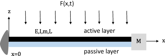
Figure 2. Unimorph cantilever subjected to distributed axial force per length.
Download figure:
Standard image High-resolution imageUsing the Newtonian or the Hamiltonian approach, the governing equation of motion for a uniform clamped-free Euler–Bernoulli beam subjected to harmonic excitation  , can be written as [22–25]:
where w(x,t) is the transverse displacement of the neutral axis (at point x and time t) due to bending, EI is the bending stiffness, and m is the mass per unit length of the beam. The steady-state response can be expressed as [26]:
where ϕr (x) is the mass normalized Eigen function, r denotes the rth vibration mode, ωr indicates the corresponding natural frequency of the rth mode and ω the frequency of the vibration source.
For a fixed-free beam with mass attached at the free end, the nth-mode flexural resonance frequency is given by [27, 28]:
where E the Young's modulus, I the Moment of Inertia, m the mass of the cantilever and Mt the mass of the proof mass. Consider a piezoelectric unimorph cantilever of length, L, and width, w. The piezoelectric layer has a density, ρp, Young's modulus, Ep, and thickness, tp. The nonpiezoelectric stainless steel layer has a density, ρs, Young's modulus, Es, and thickness, ts. Assuming that the thickness of the adhesive is small enough to be neglected, the bending stiffness EI of the unimorph is then given by [28]:
4. Numerical model
In addition to the analytical studies, numerical approaches based on the finite element method software COMSOL Multiphysics 5.4 have also been used to study the steady-state dynamics and electric response of the fabricated unimorph cantilevers. A 3D model, consisting of an active layer, a non-piezoelectric substrate made of Pernifer 45 and a proof mass at the free end of the cantilever (if exists), was built. The physical and electrical properties of the selected materials are listed in table 1. In the actual unimorph harvester, an electrode was deposited on the PZT side and an adhesive layer was used to bond the active and the passive layer. However, their influence on the analysis results can be ignored because their thicknesses are sufficiently thin compared to the other layers as to be negligible. A fine-sized mesh based on tetrahedral elements (four nodes) was applied. Each node was characterized with translations in the nodal x, y, and z directions, and electric potential V (for piezoelectric elements). The cantilever was fixed at one end and a sinusoidal body load in the z direction was applied along the beam length as a boundary load condition. To obtain the steady-state electrical response, a ground reference voltage was connected to the bottom surface of the PZT layer and an electrical circuit coupled together with an external load resistor to the upper surface. Frequency domain and time dependent analysis were performed to estimate the natural frequency and stroke of the unimorphs as a function of free length and tip mass.
Table 1. Physical and electrical properties.
| Density (kg m−3) | Young's modulus (MPa) | Poisson's ratio | Piezoelectric charge constant d33 (pC N−1) | Piezoelectric charge constant d31 (pC N−1) | |
|---|---|---|---|---|---|
| PZT5A4 | 7900 | 69 | 0.35 | 460 | 195 |
| Pernifer 45 | 8000 | 193 | 0.3 | — | — |
5. Results and discussion
5.1. Mechanical analysis
The load–displacement curves of 20 mm free length unimorph cantilevers under quasi-static loading are presented in figure 3(a). It can be observed that the ceramic can withstand more stresses in compression (where cracks appeared at approximately 3 mm deflection) than in tension (where cracks appeared at approximately 1 mm deflection). The results of this study are in good accordance with the literature which generally holds that ceramics are much more resistant to compressive stress than tensile stress [18, 29–31]. A unimorph cantilever with 40 mm free length was tested under same conditions and the results are presented in figure 3(b). From an analytical point of view, the stiffness decreases with increasing the free length. The slope in the load–displacement curve, which measures the extrinsic properties of the cantilever such as the stiffness, decreases from 0.6 to 0.1 (N mm−1), confirming this. Furthermore, the values of ultimate displacement in both compression and tension appear deviations and this can be attributed either to the inhomogeneity of the materials or uncontrolled factors during the fabrication process of the unimorph cantilevers.
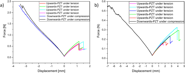
Figure 3. Load–displacement curve of unimorph cantilever with free length (a) 20 mm and (b) 40 mm.
Download figure:
Standard image High-resolution image5.2. Tip deflection
The tip deflection as a function of free length and tip mass was investigated and the results are presented in figure 4(a). As expected, the deflection of the tip increases by increasing either the length or the weight of the proof mass. Furthermore, we can notice that in all cases the deflection is less than the ultimate displacement found in the failure testing. This ensures that fatigue will be the reason for an unexpected mechanical failure and not the fact that the displacement of the unimorphs during operation exceeded the ultimate displacement.

Figure 4. Measured (a) tip deflection and (b) natural frequency as a function of free length and tip mass.
Download figure:
Standard image High-resolution imageTo estimate the damping factor of the unimorphs, the resonant frequency was determined and its variation by changing the length and the weight of the proof mass is depicted in figure 4(b). As expected, the scatter in the displacement increases with increasing unimorph length but remains about 11% of the average deflection. The scatter in the resonant frequency was considerably smaller and was of the order of 2%. It can be seen that values of the natural frequencies from the analytical results and numerical simulations using Comsol Multiphysics have good agreement with the experimental data. For analytical calculations and numerical simulations an average value of 0.03 was used as damping factor.
5.3. Power output
Figure 5(a) shows the measured generated power at different distances between the stroke limiter and the unimorph cantilever for 20, 30 and 40 mm free length unimorph cantilevers. For high values of H, there is no contact between the cantilever and the stroke limiter and therefore the power output remains stable. This is the so-called 'No contact' region. In this region, it is assumed that the cantilever vibrates according to the first mode shape (Mode 1) where all the stresses appear at the anchor. As the stroke H decreases, the cantilever hits the stroke limiter (contact region) and its dynamic behavior becomes highly non-linear. It can be observed that the power output decreases and the reason for this trend is the limitation of the deformation which results in less stresses at the anchor. As the weight of the tip mass increases, larger transverse displacements are developed and the phenomenon of power reduction is more obvious. The negative values of H indicate that the cantilever is already deformed downwards by the stroke limiter before the vibrations start (double clamped region). As a result, the cantilever deforms according to a different mode shape where stresses are mostly developed in the middle of the beam [32]. In this case, the deformation of the cantilever is significantly smaller and this explains the extremely low value of generated power.
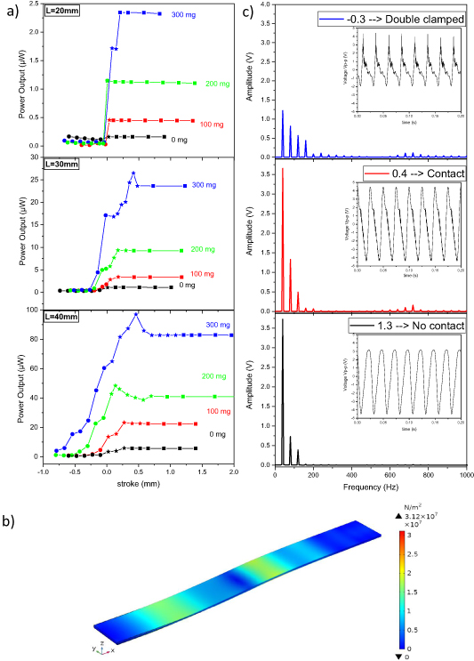
Figure 5. (a) Power output as a function of the stroke. Rectangle dots represent the 'No contact' region, star dots the 'Contact' region and circle dots the 'Double clamped' region, (b) Comsol model of a S-shape deformed cantilever; Von Mises stresses distributed along the length of the cantilever, (c) signal processing of the output voltage in the three regions using FFT.
Download figure:
Standard image High-resolution imageAs the free length of the cantilever increases, larger transverse displacements are developed making the three regions more apparent. It can be observed from figure 5(a), that the trend of the generated power for longer cantilevers is not the same as for the 20 mm length cantilever. Specifically, small peaks appear at specific distances between the cantilever and the stroke limiter indicating that the energy harvester produces more power. According to previous studies, when the tip of the cantilever hits the stroke limiter, the mass center continues moving upwards due to its inertia resulting in a large curvature in the middle of the beam. The S-shape deformation where stresses appear not only at the anchor but along the length of the beam is illustrated in figure 5(b). A consequence of this is that the PZT layer close to the clamped area is in compression while the remainder in tension and therefore the positive charge is cancelled out by the negative charge [33, 34]. This could be the reason for the decreased generated power after impact. However, it can be observed from the graphs that the power output increases at a specific stroke. After impact, the cantilever vibrates according to several modes, and stresses, possibly larger than that appeared at the anchor during the first mode, are developed. The positive influence of the stroke limiter on the generated power is in good agreement with the work produced by Wang et al [35]. The same phenomenon is not observed in the case of the 20 mm free length cantilever. It is assumed that, since the the 20 mm free length cantilever is more stiff, the S-shape due to impact does not appear and therefore the cantilever continuous vibrating according to the first mode. Since the displacement is limited because of the stroke limiter, the power output is less.
The combination of modes appearing due to the stroke limiter causes some of the parts of the cantilever to vibrate at higher frequencies. To further study this, signal analysis using fast Fourier transformation (FFT) was performed in the generated voltage signals and the results are presented in figure 5(c). One data point of each region from the power output-stroke curve of the 40 mm free length unimorph cantilever with 300 mg tip mass was selected for the analysis. The FFT reveals that the frequency content changes with the introduction of the stroke limiter. The electrical performance of the piezoelectric energy harvesters is frequency dependent. As the frequency of the vibration source is closer to the resonance frequency of the cantilever, the mechanical to electrical energy transduction is more effective. So the introduction of the high frequency movements results in an increased power output. The investigation of the energy gain at different frequencies exceeds the scope of this article.
5.4. Bandwidth
The effect of the mechanical stroke limiter on the operational bandwidth was also investigated. The laser vibrometer recorded the tip velocity of a 40 mm free length unimorph cantilever after performing frequency sweep and the results are presented in figure 6. The stroke distances were selected according to the data from figure 5(a). From the figure, one can observe that when there is no impact, the cantilever shows a sharp peak at approximately 130 Hz which is in good agreement with figure 4(b). The introduction of the stroke limiter shifts the center line of the resonance peak toward a higher frequency while preserving the same magnitude. Also, the operational bandwidth becomes wider which is beneficial for applications where small fluctuations in the ambient vibration frequency are expected. In the case where the cantilever is already deformed downwards by the stroke limiter, it can be observed that the resonant frequency increases even more. Other studies have shown that the basic vibration frequency for the double-clamped beam is higher than that of the cantilever beam by a factor of about 6.4 [36]. From the graph below, it can be seen that the difference in the natural frequency is not so significant, fact that indicates that the cantilever does not deform according to the first mode of a double-clamped beam.

Figure 6. Operational bandwidth for different regions.
Download figure:
Standard image High-resolution image5.5. Lifetime
The operational lifetime of the unimorph cantilevers in number of cycles as a function of tip mass is shown in figure 7(a). As the weight of the tip mass decreases, the stresses developed at the achor are less and therefore the lifetime increases. For 320 mg tip mass, the unimorph cantilever failed after approximately 4 min (240 cycles). In all cases, the cracks developed close to the clamped zone.

Figure 7. Operational lifetime vs (a) tip mass, (b) stroke. (c) Time dependent stroke of the cantilever using Comsol.
Download figure:
Standard image High-resolution image
To investigate the effect of the single-side deflection limitation on the lifetime, the unimorph cantilever with 320 mg tip mass was used as it was the most extreme case. The sample was initially placed in such way where the compressive displacement of the PZT layer was limited. When the unimorphs bend downwards, the movement is impact-free. From figure 7(b), the positive influence of the stroke limiter on the lifetime is clear. Pillatsch et al [18] obtained a similar lifetime trend when the deflection of a bimorph cantilever was limited. To investigate the influence of the tensile stresses in the lifetime of the unimorphs, the PZT layer was placed as the bottom layer. A clear improvement in lifetime is obtained in the case where the tensile displacement of the PZT layer is limited by the stroke limiter. For low values of stroke, the unimorphs can exceed one day of operation. To further investigate the difference in lifetime, the stroke was numerically estimated and the results are shown in figure 7(c). It can be observed that the usage of a stroke limiter leads to an assymetric deflection. In the downwards bending movement, the unimorph deforms further than 0.2 mm and this is the reason for the difference in the results in figure 7(b). Furthermore, the high frequency movements introduced due to the impact can not be captured in the steady-state dynamics response of the unimorph. The difference between the experimental results and the numerical simulations can be attributed to the inhomogeneity of the layers in the actual unimorph cantilever leading to different modes of deformation (e.g. torsion).
6. Conclusion
The adoption of the single-side stroke limiter has a positive influence on the electrical and structural performance of a unimorph cantilever. In general, the generated power decreased along with a decrease in the deflection due to the less strain levels. However, a small increase in the generated power was observed when the deflection was minimally constrained and this trend seems to appear as the stiffness of the cantilever decreases. This can be unambiguously linked to the high frequency movements where the mechanical to electrical energy transduction becomes more effective. On the other hand, the lifetime was significantly improved, especially when the tensile displacement was limited. The structural and electrical performance of a unimorph cantilever can be improved when the tensile deflection of the ceramic layer is minimally constrained while keeping the deflection on the compressive side unconstrained. This study provides guidance in designing piezoelectric energy harvesters and opens the opportunity for more effective energy harvesting for longer period mainly through compressive operation.
Acknowledgments
During this project, Professor Groen tragically passed away. The remaining authors would like to thank him for his contribution in this and many other works. He was a valued colleague and friend, and he will be greatly missed. The authors would also like to thank Dr Andre Bossche and prof Dr Paddy French for their coordination of the work done in this study. This work is part of the research program Citius, Altius, Sanius with project number P16-28, which is financed by the Dutch Research Council (NWO).
Data availability statement
All data that support the findings of this study are included within the article (and any supplementary files).