

Abstract
Design of hierarchical micro-nanostructured zinc oxide nanorods (ZnO NRs) grown on microscale curvature surfaces is suggested for the effective contact area changes between the top and bottom triboelectric layers under mechanical stimuli. The microscale structures of carbon-fiber-reinforced plastics (CFRPs) by means of simple fabrication methods are preserved. By combining micro and nanostructures, they make it possible to be a spacer-free, ultrathin, and highly sensitive triboelectric sensors (TESs). The flexible TES shows a high-pressure sensitivity and bending sensing capability which enables the detection of repeatedly increasing bending because this structure shows the enhanced contact area changes owing to the effective soft spreading layer of flexible CFRPs. In addition, these CFRP-based TESs can detect tensile strains and impact forces, which suggest potential applications as self-powered structural sensors.
Export citation and abstract BibTeX RIS
1. Introduction
Flexible and thin electronic sensors, which are based on different physical transduction mechanisms, including piezoresistivity [1–7], capacitance [8–12], piezoelectricity [13–17], and triboelectricity [18–23], have attracted considerable interest in major research areas for various applications in artificial skins, automotive industries, sustainable power management, and robotics. Moreover, various flexible and thin devices have been developed for practical applications such as pressure sensors and energy harvesting [8, 21, 24–26]. Self-powered sensors that can generate power by harvesting ambient energy sources, such as mechanical energy from various mechanical stimuli and thermal energy from temperature differences, have great potential in the future of sensors. Several researches are available on energy conversion systems based on piezoelectric [13, 15, 27], thermoelectric [28–30], electromagnetic [31, 32], and triboelectric [18, 33–35] effects to convert various energy sources into electricity. Especially, triboelectricity, based on physical principles of triboelectrification and electrostatic induction, is a common phenomenon that occurs because of charge generation during the contact and separation process of two different materials. The devices based on triboelectric effect can provide more diverse materials that have flexible and thin properties, and higher power generation than other energy harvesting devices. Therefore, the triboelectric devices can be used as self-powered sensors for detecting mechanical stimuli. Self-powered sensors using triboelectric effect have been developed but they have several limitations such as bulk spacers, arch shapes, and 3D structure impeding flexible and thin structures.
Recently, carbon-fiber-reinforced plastics (CFRPs) have received much attention in energy harvesting [36, 37], structural health monitoring [5, 38–40], and various sensing fields [3, 41–43] because they have outstanding electrical properties and specific mechanical properties. Energy harvesting using CFRPs is a thermal technology for generating electricity by transferring waste heat from a heat source to a heat sink through n/p thermoelectric materials. It is applicable in very limited place where the temperature difference is very high, and the power generated is low. Mechanical sensing using CFRPs has limited sensitivity and is difficult to apply in several practical procedures owing to their rigidity.
Here, we propose zinc oxide nanorods (ZnO NRs) grown on microscale curvature surfaces of CFRPs having large surface areas for developing spacer-free, ultrathin, highly sensitive, and flexible triboelectric sensors (TESs). By fabricating hierarchical micro-nanostructures with novel methods that can increase the surface area and utilize space-saving design, TESs are known to be highly sensitive and ultrathin devices owing to their unique micro-nanostructures. The self-powered TESs can sufficiently light up a white 8-LED lamp using small pressure. The rigid crystalline ZnO NRs on flexible CFRP surfaces provide ultrafast responses during contact and separation processes. In addition, CFRPs having flexibility and microscale curvature surfaces can detect tensile strain and have impact sensing capabilities. In this study, we demonstrate a novel design using micro-nanostructure that overcomes bulky geometry, which in turn facilitates their applications in flexible and thin devices.
2. Results and discussions
Schematic images present the fabrication process of the fully unburied micro nanostructure and ultrathin TES (figure 1(a)). For the fabrication of ultrathin and micro-nanostructured TESs, woven carbon fiber (WCF) was dipped into a PDMS solution and dried at room temperature for 1 h on the hanger. After the dipping and drying process of WCF, WCF wetted with PDMS was spin-coated for 30 s at 3000 rpm to make ultrathin and micro structured surface of WCF. Finally, PDMS was cured at 70 °C for 2 h. To fabricate the other ultrathin, flexible triboelectric layer, ITO coated with PET was spin-coated with PDMS (3000 rpm for 30 s), resulting in ultrathin and flexible TESs with a total thicknesses of approximately 500 μm. The TESs measured approximately 300 mm by 300 mm, and the working distance between the two triboelectric layers separated using a Kapton tape as spacer was 0.2 mm. Each side of the electrode was connected to a Cu strip, and it was adhered using silver paste to reduce the contact resistance and covered with a polyimide tape to fix it firmly (figures 1(b) and (c)). Figure 2(a) shows the surface of WCF embedding PDMS without the spin coating process. However, after the spin coating process, the unburied surface structure of CFRP is shown in figure 2(b). ZnO NR array templated CFRP surfaces acting as a triboelectric active layer at the bottom side were synthesized on conducting CFRP surface using a hydrothermal growth method of ZnO. ZnO NRs were grown on the micro structured surfaces of CFRPs as shown in the combination of micro-nanostructure (figure 2(c)).
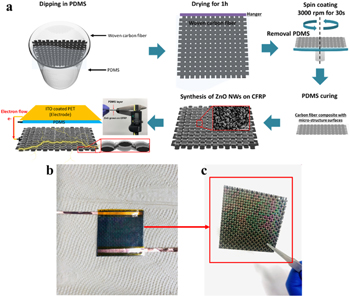
Figure 1. (a) Schematic illustration of the fabrication process for the ZnO growth on carbon-fiber-reinforced PDMS (CFRP) composites TESs. Inset photo highlights the ultrathin triboelectric layers (510 μm). (b) Photograph of the fabricated sensor. (c) Photograph of a ZnO-grown triboelectric layer (CFRP).
Download figure:
Standard image High-resolution image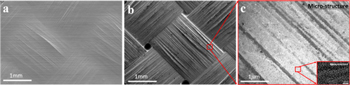
Figure 2. SEM image of a hierarchical micro-nano structured triboelectric device. (a) Surface structure of CFRP without spin coating process. (b) CFRPs showing their surface structure with spin coating process. (c) Their unburied microstructure without embedding PDMS. Inset is the magnified image of the ZnO nanostructure.
Download figure:
Standard image High-resolution imageThese micro-nanostructures with large surface areas provide higher triboelectric output performances compared to other triboelectric devices made using the same material without the structures [44]. In addition to the micro-nanostructure effects, the carbon-fiber-reinforced PDMS composite, which used a flexible and deformable matrix, can produce effective deformation on the surface of CFRPs under pressure to increase the contact area. Figure S1 is available online at stacks.iop.org/SMS/29/025002/mmedia illustrates the contact area changes between a flat PDMS surface and ZnO NRs on the microstructured surface of CFRPs under pressure. With respect to the combination of micro-nanostructures, the number of contacting ZnO NRs increase as the pressure increases over a small-time interval. Basically, the increase in the contact area of individual ZnO NRs is responsible for outstanding triboelectric performances.
The schematic illustrations in figure 3 show the working mechanism of self-powered TESs during the contact and separation processes between the flat surfaces of PDMS layers and ZnO NRs on the microstructured surface of CFRPs. According to the triboelectric series, the negative and positive charges were distributed at the PDMS and ZnO NRs during the contact process. During the releasing and compensating electrical equilibrium, the electrons flow continuously from the top electrode to the bottom electrode. Thereafter, the TES reaches the charge equilibrium state and the two triboelectric layers can be pressed to become closer again; the direction of electron flow is reversed because the electric charges were moved for neutralization. Therefore, triboelectric voltage and current are continuously produced in repeated contact and separation processes.

Figure 3. Schematic illustration of the working principle of self-powered TESs showing triboelectric charge generation and current flow during the contact and separation processes between the ZnO grown on CFRPs and PDMS layers.
Download figure:
Standard image High-resolution imageThe maximum power density of self-powered TESs is 242.6 μW cm−2 at an external load resistance of ∼200 MΩ under a vertical pressure of 5 kPa at 5 Hz (figure 4). As shown in figure 5(a), the triboelectric output voltage increases on increasing pressure. Our TESs exhibit the highest-pressure sensitivity (∼0.98 V kPa−1 up to 19.74 kPa), which is higher than the previous TESs based on hierarchical microstructured sensors (∼0.55 V kPa−1 up to 19.8 kPa) [45]. Figure 5(b) shows the measured output voltages of the ZnO NRs on the surface of CFRPs under the external pressure 7.85 kPa with interval time. Voltage curves show repeated positive and negative peaks at the instants of pushing and separating, respectively. Our TESs can sufficiently light up eight white LEDs during the contact and separation processes with small forces(0.08 kgf) (figure 5(b)). Figure 5(c) shows fast contact and separation response times of TESs under small weight (1 g) owing to their hierarchical micro-nanostructures and the immediate change in contact area between the rigid crystalline ZnO NRs and PDMS. The hierarchical micro-nanostructured TESs exhibit excellent mechanical durability with repeatable triboelectric output voltage generation during 10 000 cycles of pushing with a vertical pressure of 17.5 kPa at 1 Hz. (figure 5(d)).
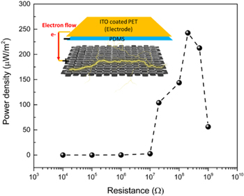
Figure 4. Triboelectric output variations of power density with an external load resistance from 104 to 109 Ω under vertical pressure 5 kPa at 5 Hz.
Download figure:
Standard image High-resolution image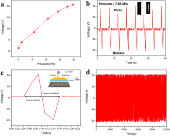
Figure 5. Pressure sensing capability of ultrathin flexible TESs. (a) Triboelectric voltage variations and pressure sensitivities with the applied pressure. (b) Triboelectric voltage generations under the external pressure 7.85 kPa with interval time and the inset of the capability for lighting 8-white LEDs driven by self-powered TES. (c) Response times of contact and separation under a small weight with small surface area (1 g). (d) Output voltages with cycled vertical pressure of 17.476 kPa with 1 Hz applied to the TESs over 10 000 cycles.
Download figure:
Standard image High-resolution imageFigure 6 shows the bending detection capability of ultrathin flexible TESs. The triboelectric voltage generation induced by bending was determined by the contact area changes between the upper and bottom layers of TES. For applying the bending induced tensile stress and illustrating its mechanism, TES was subjected to forces at both ends which induced a bending effect as shown in figure 6(a). When the applied forces at both ends bend the TES, tensile stress is induced in center of the TES as seen in equation (1).

where σx is the x-directional tensile stress induced by bending, F2 is the force at the center of the TES, A is the area of cross section, M1 is the moment induced by F1 at the center of the TES, y is the distance measured from the center axis of the cross section , and I is the moment of inertia.
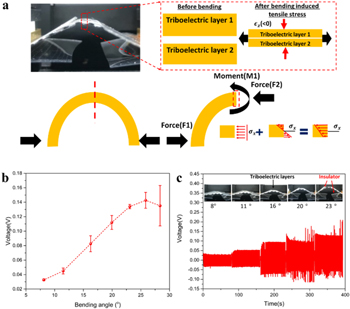
Figure 6. Detection capabilities of bending induced tensile stress of ultrathin flexible TESs. (a) Schematic illustration of gap distance change of TESs under bending induced tensile stress and theoretical analysis of forces. (b) Triboelectric voltage variations under bending induced tensile stress with different bending angles. (c) Capability to monitor the increasing bending angle motion by bending sensitive TESs.
Download figure:
Standard image High-resolution imageFrom this x-directional tensile stress, tensile strain  at the center of the TES through the two thin layers of the TES is expressed as

where ν is the Poisson's ratio, E is the elastic modulus, σy is the y-directional tensile stress, and σz is the z-directional tensile stress.
Tensile strain can induce the contact area change between the two thin layers of the TES during the bending process. From this mechanism, we observe that our ultra-flexible TESs are sensitive to bending induced tensile stress. The increased bending induced tensile stress along with the bending angle increases the triboelectric output voltage of TES as shown in figure 6(b). When the ultrathin and flexible TESs are repetitively subjected to increasing bending angles, the highly sensitive TESs can accurately detect the degree of the bending angle through the magnitude of triboelectric output voltages (figure 6(c)). Furthermore, the durability of TESs under bending-induced tensile stresses was tested by applying multiple cycles of bending angle (16°) at a frequency of 0.5 Hz, and TESs showed reliable, uniform sensing performance up to 5000 cycles (figure S2).
In addition to the detection of bending induced tensile stress, our ultrathin and flexible TESs can detect 3-point bending applied through the combination of pressure and bending. The experimental schematic and TES response for repeated 3-point bending under curvature (4.061 × 10⁻³(mm−1)) are shown in figure S3. When the center bar for applying the 3-point bending induces a slight vertical pressure, the generated voltage under the 3-point bending of TES is higher than that under the bending induced tensile stress because both pressure (middle portion of the sample) and bending occur during the 3-point bending process.
Our ultrathin and flexible TESs consisting of CFRP that have electromechanical properties can also detect tensile strain and impact force. Figure S4(a) shows that relative resistance changes increase with increasing tensile strain. The increase in relative resistance can be attributed to the combination effects of the piezoresistivity in flexible matrix and the contacts of carbon fiber as a result of the Poisson's effect along the lateral direction [46]. The fibers in a PDMS matrix have greater freedom to move, enhancing the piezoresistive effect which increases the contact electrical resistance owing to the alignment of the fibers [43]. Subsequent cycling tensile loading–unloading was conducted by straining the composite material as shown in figure S4(b), which presents fifteen loading–unloading cycles. Relative resistance follows tensile strain, however there is a small reduction in the amplitude ratio of R/R0 as the number of tensile cycles increase, which may be due to matrix viscoelastic effects captured by the electrical signal.
For detecting impact force and investigating ZnO effect during the impact test, impact energy of 10 J, which is more than the penetration threshold of the specimen, was applied. Figure 7(a) indicates that the relative resistance of CFRP damaged by the impact was changed. The outstanding difference is that the change in relative resistance of the sample growing ZnO on the CFRP surface is higher than that of pristine CFRP. Figure 7(b) shows that CFRP with ZnO grown on its surface induces greater impact force because ZnO enhances the absorbed impact energy [47].

Figure 7. Impact sensing capabilities of ZnO growth on CFRPs. (a) Resistance changes after the impact test and (b) absorbed impact energy-time response.
Download figure:
Standard image High-resolution image
3. Conclusions
In summary, ultrathin, highly sensitive, and flexible TESs using CFRPs were developed by hierarchical architectures comprising microstructured surfaces of CFRPs and ZnO NRs on their surfaces having large surface areas. The hierarchical geometry of ZnO NRs on the microstructured surfaces of CFRPs could enhance the effective contact area change between triboelectric layers without bulk extra spacers and facilitated ultrathin, flexible, and highly sensitive design. In addition, flexible CFRPs can effectively change the deformation of their surfaces and increasing the number of ZnO NRs on the surfaces of CFRPs in contact with PDMS layers significantly enhances the triboelectric output performances as well as pressure and bending sensitivities. Our self-powered TESs exhibited the highest power density (∼242.6 μW cm−2) and lit an 8-white LED lamp. Moreover, our combined micro- and nano-structure design produces fast-responsive time TESs during the contact and separation processes. In addition, CFRPs could detect tensile strain and impact force, and ZnO NRs on the surface of CFRPs can endure greater impact energy. The spacer-free and monolithic design of ultrathin and flexible TESs based on CFRPs could aid various broad applications such as structural health monitoring devices, automotive industrial applications, power generation, and humanoid robotics.
4. Experimental section
4.1. Materials and synthesis of ZnO NRs
The WCFs (T-300, density 1.76 g cm−3, 3 K plain weave) for making WCF composites were supplied by Toray corporation (Japan). For the growth of ZnO NRs on the surface of WCF composites, zinc nitrate hexahydrate (Zn (NO3)2 · 4H2O) and hexamethylenetetramine (C6H12N4) were supplied by Sigma-Aldrich. Indium tin oxide (ITO) coated Polyethylene terephthalates (PETs) (surface resistivity 60 Ω sq−1, thickness 5 mil sheet) supplied by Sigma-Aldrich were used for the triboelectric layer substrate and electrodes.
Polydimethylsiloxane (PDMS) prepolymer and curing agent (Sylgard 184, Dow Corning) with the ratio of 10:1 were used for the matrix of carbon-fiber-reinforced PDMS composite and triboelectric layers.
To synthesize the vertically aligned ZnO NRs, DC Sputtering system is used for deposition of Zn (thickness:5 nm) on CFRPs by DC negative voltage. To prepare the growing solution for ZnO NRs, Zn (NO3)2 · 4H2O and C6H12N4 were mixed in DI water and dispersed by stirring machine. After preheating the growing solution for 5–10 min at 100 °C in convection oven, the DC sputtered Zn coated CFRP substrates were floated onto the surface of the growing solution for 150 min and washed with distilled water.
4.2. Characterizations of materials and triboelectric performances
The morphologies of millimeter-scale, microscale, and nanoscale ZnO grown on PDMS-WCF composites were characterized by field-emission scanning electron microscopy (FE-SEM) (S-4800, Hitachi, Japan). The vertical pressure test was applied via a pushing tester (Push machine, SnM, Korea) with a high-frequency (5 Hz) pushing speed controlled by moving displacement. Bending and tensile tester (Bending machine, SnM, Korea) with 100 μm resolution bending speed were used for measuring bending and tensile sensing capabilities. A universal testing machine (UTM, 5982, Instron) was used for measuring the 3-point bending properties of samples. The vertical pressure and bending stress induced electrical properties were stored by triboelectric voltage, current, and electrical resistances using an electrometer (2002 Multimeter, Keithley, US). To investigate the response time of TESs, 1 g weight (CORTECH, Korea) was used for measuring the contact and separation response times of TESs.
Acknowledgments
This work was supported by the Human Resources Development grant through the Korea Institute of Energy Technology Evaluation and Planning (KETEP) funded by the Ministry of Trade, Industry and Energy (MOTIE) of Korea (Grant No. 20194030202400) and the 2019 Research Fund (1.190011) of UNIST (Ulsan National Institute of Science and Technology).