

Abstract
A new type of space crawling robot was proposed for spacecraft maintenance missions and a nanoscale microarray structure was designed as the robot foot structure. In this study, a carbon nanotube array structure was adopted as the adhered nanoscale microarray structure of the robot foot. A theoretical model of the carbon nanotube structure was established, and the influence of the structural parameters of the carbon nanotube array on its adhesion characteristics was analyzed. A force model of carbon nanotube arrays on different roughness surfaces and under different preloads was established using the discrete element software, EDEM. A simulation of the desorption process of the carbon nanotube array structure in the normal and tangential directions was conducted. The adhesion characteristics of the carbon nanotube structure were analyzed. On this basis, the carbon nanotube microarray structure was fabricated using chemical vapor deposition, and a force test system was established on the platform of a scanning electron microscope to test the adhesion force of the carbon nanotube array in a vacuum environment. The influence of preloading and roughness on the adhesion characteristics of the carbon nanotube array structure was analyzed.
Export citation and abstract BibTeX RIS
1. Introduction
With the recent progress of technology, there has been continuous growth and improvement in space exploration [1]. On-orbit servicing technology is a highly prospective yet challenging subject in the high-tech aerospace industry [2, 3]. This study proposed a crawling robot that could adhere to a target spacecraft. The robot was designed to move to the corresponding position in a crawling manner or via a turnover to control the target in orbit, thus expanding the working space and mission function of a space manipulator.
Currently, adsorption techniques applied to crawling robots generally include vacuum, positive-pressure, electromagnetic, permanent magnet, adhesive, and dry adhesive adsorption [4–7]. Because of the characteristic vacuum environment in space, the vacuum and positive-pressure adsorption techniques cannot be used. Moreover, most spacecraft surfaces are manufactured using aluminum alloys, titanium alloys, carbon fiber, thermal control multilayers, solar wing cells, and other materials, none of which have magnetic permeability. Thus, electromagnetic and permanent magnet adsorption also cannot be used in the space environment. The dry adhesive adsorption method is essentially a bionic gecko's setae adsorption technique, which has the following advantages: it is easy to maintain the adhesion state once an attachment is made; attachment and detachment occur at high speed; the adhesion is not affected by the surface material; and there are no environmental requirements. Therefore, it is very suitable for applications in outer space technology.
Hence, studies on the adhesive feet of space crawling robots based on the understanding of the dry adhesion mechanism of the soles of an animal such as a gecko, are of great value and practical significance. A number of scholars throughout the world have conducted considerable research on the adhesion mechanism, array processing, and performance testing of an imitation gecko adhesion array. There have been attempts to fabricate surface patterns with polymers to mimic the structure of setae and spatulas. And it hard to requires the ability to remain clean from dust and other contaminants. Tip ending shape design of fiber arrays is one of the important parameters for developing contamination-resistant fibrillar adhesives. Other scholars use the electrostatic element of an electrostatic/ gecko-like adhesive to repel dust particles, which have been shown to significantly affect adhesion and reliability [8–18]. NASA use micro array structure achieve robotic gripper that can gently grasp, manipulate, and release both flat and curved uncooperative objects as large as a meter in diameter while in microgravity. The extreme conditions of space, such as high and low temperatures, vacuum, and radiation bring about new requirements and challenges for the design and development of these robots [19–21]. Carbon nanotubes are formed by covalent bonding between carbon atoms. Each carbon atom in a single-walled carbon nanotube is connected to three adjacent carbon atoms to form a hexagonal lattice structure. CNTs are highly resistant to damage, whether it be mechanical, chemical or radiation induced. It has strong adhesion force and space environment adaptability [22, 23].
The shear adhesion force of carbon nanotubes is much stronger than the normal adhesion force. This anisotropic force distribution is due to the shear-induced alignments of the curly segments of the nanotubes. By using carbon nanotube arrays are dominated by a straight body segment and curly entangled top show macroscopic adhesive forces of 100 N per square centimeter. It has strong adhesion force and space environment adaptability [24–27].
The advantage of carbon nanotubes over other Organic polymer adhesive material is that they can achieve strong adhesion at high and low temperatures. Organic polymer materials are not as adaptable to high and low temperature environments as carbon nanotubes. However, the size of the array is too small, so it is difficult to process a regular array of carbon nanotubes, and the bottom of the array is fragile and easy to be broken. There are still many problems to be solved to realize the application of carbon nanotubes in the foot of space crawling robot.
In this study, using carbon nanotube arrays as gecko robot-attached microarray structure. We did not consider the adhesion of the carbon nanotubes to the side contact after bending. We analysis the adhesion force of the end of straight carbon nanotubes to the contact surface. The adhesion and desorption behavior of carbon nanotube arrays was simulated using the discrete element software, EDEM [28, 29]. The influence of the structural parameters of the adhesion array on the adhesion characteristics was analyzed, providing knowledge on on-orbit service technology.
2. Materials and methods
2.1. Research on adhesion and crawling function of space robots
Owing to the uncertainty of surface topography of the target spacecraft, the robot needs strong obstacle surmounting ability, so revolute joint drive is considered as the motion mode of the robot. The maximum height of the obstacle that a conventional robot can cross is related to the structural size of the robot. There is no gravity in space, and consequently, no 'top and bottom' for the robot. As it is suspended in space, the robot can overcome an obstacle via a turnover movement. The size of the obstacle that it can overcome is not affected by the size of the robot. The gecko has four legs that are symmetrically distributed. In addition to the gecko's sole, each leg of the gecko has three joints, offering 5 degrees of freedom: a cross-joint between the body and the thigh bone, a knee joint between the thigh bone and the calf tibia, and an ankle joint between the calf tibia and the sole of the foot [30].
Through an analysis of the gecko's body structure and motion, as shown in figure 1 the robot mechanism configuration was proposed. The robot has five degrees of freedom for each leg and its joint freedom is 2–1–2. The ankle joint of the robot had two orthogonal degrees of freedom, while the knee joint had one degree of freedom, and the joint connected to the body had two orthogonal degrees of freedom. The head of the robot can be designed with two small manipulators which can achieve high precision repair operation of spacecraft through the cooperation of multiple robots. This mechanism has the following advantages after meeting the above requirements:
- (1)It offers a variety of plane motions. The robot can move from one surface to another surface as shown in figure 2. The relative position of the two surfaces could be from −90° to 90°.
- (2)The robot has a symmetrical structure. In space environment, there is no difference between top and bottom for a robot, and also there is no difference between left and right for a robot. The space climbing robot can move from one surface to the other surface by crawling movement or flip movement which have ability to complete tasks in any state.
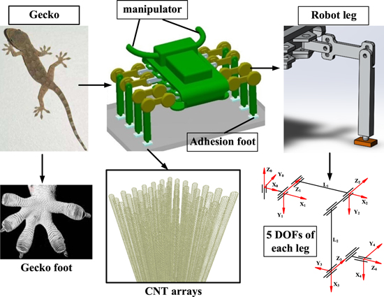
Figure 1. Gecko like Robot mechanism [14].
Download figure:
Standard image High-resolution imageThe adhesion of the robotic foot plays a key role in space robots achieving crawling movement. This movement is driven by alternately attaching and detaching the contact surfaces, and by joint driving. The adhesion of the foot to the contact surface in space directly affects the reliability of the robot to adhere to the spacecraft surface and the stability of its motion state. To achieve fast and reliable adhesion between the foot and contact surface, the end of the foot was designed with bionic setae.
A gecko's feet as seen under a microscope in figure 1. The photograph shows that the bottom of the gecko's foot is covered with millions of setae. There are approximately 5000 setae, 30–130 μm in size, existing within an area of 1 mm2; i.e. there are nearly 500 000 setae on one foot. Each seta has 400–1000 flosses. The spatulas have a length of about 0.5 μm, a width of about 0.2 μm, and a thickness of approximately 5 nm. The nanosize spatulas contact firmly to the surfaces to generate van der Waals forces to ensure that the feet attach to the surface [31]. Similar to the gecko's nanoscale setae structure, a carbon nanotube array was proposed as the micro-adhesive structure of the space robot foot [32]. Coupled with their potential low cost due to the abundance of carbon and the miniscule quantities of material required in applications, it is clear why they are an exciting material for research.
2.2. Theoretical model of carbon nanotubes
Based on the microstructure of carbon nanotubes, a contact mechanics model of a single carbon nanotube in the vertical direction to the contact surface was established. The van der Waals forces of each atom on the carbon nanotubes and each atom on the contact surface are added to obtain a mechanical relationship between the individual carbon nanotubes and the contact surface. The intermolecular interaction potential is expressed by the Lennard–Jones potential, given by
where r is the distance between the molecules, σ is the distance between atoms based on the van der Waals force acting at zero, and ε is the van der Waals energy between two atoms when the van der Waals force is equal to zero. The interaction between molecules can be obtained by the differentiation of the van der Waals energy between molecules:

The van der Waals force between a single particle and a macroscopic object can be obtained by integrating one atom over the van der Waals force of all atoms in another object:
where h is the vertical distance between the single atom and one atom in macroscopic object, and r is the horizontal distance between the single atom and one atom in macroscopic object. ρ is the density of atoms in macroscopic objects. The van der Waals force between a single atom and a macroscopic object can be obtained by integrating one atom over the van der Waals force of all atoms in another object. Based on formula (3), the adhesion force of a single carbon nanotube on the contact surface can be obtained by adding the van der Waals forces between each carbon atom on a single carbon nanotube and a macroscopic object. Because of the complicated arrangement of carbon atoms in carbon nanotubes, as shown in figure 3, the carbon atoms in the carbon nanotubes are arranged in a hexagonal pattern, which can be equated into a diamond shape with two carbon atoms in each diamond shape, as shown in figure 3(c). Figure 3(d) is the sum of the van der Waals forces between the two atoms in each diamond shape and the contact surface, equivalent to van der Waals forces between one simplified atom and the contact surface. The simplified atoms are arranged in a regular way, and the van der Waals forces between the carbon nanotubes and the contact surface are obtained by superimposing the van der Waals forces of each simplified atom.
A schematic diagram of the atomic distribution of the carbon nanotubes after simplification is shown in figure 2(e). The van der Waals force between each carbon atom and the contacted macroscopic object is superimposed to obtain the adhesion expression of a single carbon nanotube:
The definitions of the variables in the equation are listed in table 1.
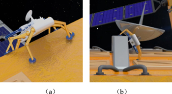
Figure 2. The robot move from one surface to another surface(a) The relative position of the two surfaces is −90 degree. (b) The relative position of the two surfaces is 90 degree.
Download figure:
Standard image High-resolution imageTable 1. Variable definitions.
| Chiral angle | θ |
| Perimeter of the carbon nanotubes | L |
| Atomic density on the surface | ρ |
| van der Waals force bond energy between two atoms | ε |
| Force balance distance between two atoms | σ |
| Distance between carbon atoms in a carbon nanotube | ac–c |
| Length of carbon nanotube unit vector | a |
| Distance between the end of the carbon nanotube and the attached surface | d |
For a carbon nanotube with a chiral angle of θ = 30°, its adhesion expression is
For a carbon nanotube with a chiral angle of θ = 0°, its adhesion expression is
m is the number of diamond shapes along the circumference of the carbon nanotubes. 
2.3. Simulation of adhesion characteristics of multiwalled carbon nanotube arrays
Geckos can adhere to surfaces of different roughness while crawling. Based on the gecko's setae structure, a carbon nanotube array model was proposed, and the contact model between the carbon nanotube array and the rough surface was established by using the discrete element method [33, 34].
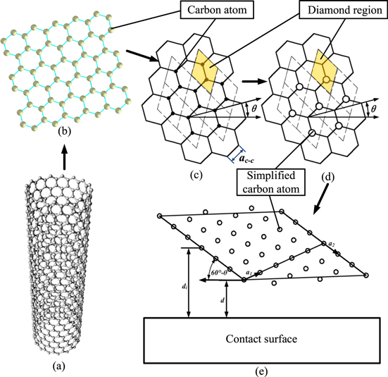
Figure 3. Simplification of the atomic arrangement in carbon nanotubes (a) Schematic diagram of the carbon nanotube microstructure. (b) Atomic arrangement in carbon nanotubes. (c) Decomposition of carbon nanotubes (d) Simplified atomic arrangement in carbon nanotubes. (e) A schematic diagram of the atomic distribution of the carbon nanotubes after simplification.
Download figure:
Standard image High-resolution imageThe discrete element method is a numerical simulation method used to solve the modeling problems of multiparticle systems by tracking the movement of particles, and the interaction between particles and the environment with time [35]. Currently, there are two kinds of discrete element simulation computer software: PFC and EDEM. Compared to PFC, EDEM has a better user interface. In addition to this, it has good parallel computing efficiency and speed, which is important as particle calculations can reach a magnitude of millions. This study used EDEM to model and simulate the carbon nanotube array. A model with three roughness contact surfaces was established. The scale of the simulation model of carbon nanotubes is nanoscale. The influence of roughness on the adhesion characteristics of carbon nanotubes was analyzed from the microscopic perspective through simulation, so we choose 650 160 nm for roughness.as shown in figure 4.

Figure 4. Modeling process for three roughness surfaces. (a) 6 nm peak-to-valley distance. (b) 50 nm peak-to-valley distance. (c) 160 nm peak-to-valley distance.
Download figure:
Standard image High-resolution imageAs the adhesion characteristics of carbon nanotubes are mainly considered in the simulation software, the multi-walled carbon nanotubes are simplified. The discrete element model is modeled according to the structure of single walled carbon nanotubes to simulate multi-walled carbon nanotubes with equal magnification. The Hertz–Mindlin with Bonding contact model is adopted as the simulation model of the bonds between carbon atoms. The irregularity of the end of the carbon nanotubes and the arrangement of atoms with the defective structure were not considered, and the modeling was performed with a regular arrangement. Figure 5 shows a discrete element model of a 7 × 7 carbon nanotube array. The radius of a single carbon nanotube was 10 nm and the spacing between carbon nanotubes was 50 nm. The bonding between particles was represented using a bonding model to establish a single carbon nanotube model. In the discrete element software, the van der Waals force between the carbon nanotube particles and the contact surface was simulated using the Johnson–Kandall–Roberts (JKR) model.
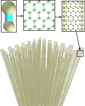
Figure 5. Discrete element model of the carbon nanotube array.
Download figure:
Standard image High-resolution imageOn this basis, attachment and detachment processes of the carbon nanotube array onto the rough surface were simulated. By pre-pressing, the ends of the carbon nanotube arrays were brought in contact with the surface, following which the normal preload was removed.
Finally, the carbon nanotube array was separated from the surface of the object by normal and tangential stretching. The normal and tangential adhesion forces of the carbon nanotube array during detachment were obtained, and the adhesion characteristics were analyzed. Figure 6 show the normal and tangential detachment processes of carbon nanotube arrays, respectively.
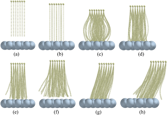
Figure 6. Carbon nanotube array desorption process. (a) Original state. (b) Contact. (c) Preload. (d) Unloading. (e) Normal detachment. (f) Separation from the surface by normal detachment. (g) Tangential detachment. (h) Separation from the surface by tangential detachment.
Download figure:
Standard image High-resolution image2.4. Experimental study on adhesion characteristics of multiwalled carbon nanotube arrays
The carbon nanotubes were fabricated by chemical vapor deposition which using acetylene as carbon source, argon as carrier gas, hydrogen as working gas and iron ion as catalyst. Firstly, the surface of silicon wafer is heated to form a silicon oxide film. Then the surface of silicon oxide was deposited by electron beam equipment to obtain alumina layer and iron ion catalyst. The silicon wafer was placed in a CVD tube furnace. After vacuum extraction, argon and hydrogen were injected into the furnace and heated to 500 °C. Acetylene gas was injected into the furnace and heated to 800 °C for 20 min to obtain the carbon nanotube array. The adhesion test of carbon nanotube array is divided into two parts. Firstly, the adhesion characteristics of carbon nanotube array are tested through AFM. As illustrated in figure 7(a), a micro force test platform with AFM was built in a scanning electron microscope. Due to the small size of the AFM, the area of the carbon nanotube array is 2 mm * 5 mm which was much larger than AFM. In order to test the micro adhesion force of carbon nanotube array, a single group of carbon nanotubes was stripped from carbon nanotube array by using a probe which controlled by two-dimensional moving platform [24, 25]. A single group of carbon nanotube array and the contact surface were fixed at the ends of the two motion mechanisms of the force test platform, and the adhesion test of the carbon nanotubes was performed. The diameter of the carbon nanotube array was 0.4456 μm. The area of the a single group of carbon nanotube array was 0.156 μm2 and its length was 10 μm.
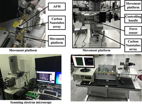
Figure 7. (a) Force test platform built in a scanning electron microscope. (b) Two-dimensional force test platform.
Download figure:
Standard image High-resolution imageBase on the analysis of carbon nanotubes array adhesion property in microcosmic, test carbon nanotube array adhesion property from macroscopically through a two-dimensional force test platform, as show in figure 7(b). The area of the carbon nanotube array is 2 mm2 * 5 mm2.
3. Results
3.1. Theoretical model of carbon nanotubes
By solving formula (5), the relationship between the adhesion force of the carbon nanotubes with chiral angle θ and the distance d from the contact surface of the object can be obtained, as shown in figure 8.
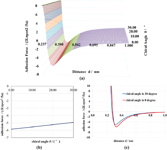
Figure 8. (a) Relationship between the adhesion force of carbon nanotubes and the chiral angle θ and spacing d. (b) Relationship between the extreme adhesion force and chiral angle of carbon nanotubes. (c) Relationship between the adhesion force of carbon nanotubes and distance which chiral angle is 0° and 30°.
Download figure:
Standard image High-resolution imageFigure 8(b) shows a graph demonstrating the relationship between the maximum adhesion force and the chiral angle of the carbon nanotubes. The distance d in figure 8(b) is 0.329 nm. When the d is too far, the adhesion force tends to be 0. When d nearly 0, the repulsive force tends to be infinite. The chiral Angle of carbon nanotubes is related to the Angle of carbon–carbon bond. When the carbon–carbon bond is perpendicular to the tube axis, the chiral Angle is 0°. When the carbon–carbon bond is parallel to the tube axis, the chiral Angle is 30°; As the Angle of the carbon–carbon bond changes, the chiral Angle increases from 0° to 30° and then decreases to 0°. Figure 8(c) shows the relationship between the adhesion of carbon nanotubes and distance, when the chiral angle is at its maximum and minimum values. The results calculated are shown in table 2.
Table 2. Maximum adhesion force under two chiral angles.
| Carbon nanotubes | |||
|---|---|---|---|
| Chiral angle | θ | 0° | 30° |
| Distance | d | 0.329 nm | 0.329 nm |
| Adhesion force | F(d) | −5.848(2Lπρεσ2/5a) | −4.968(2Lπρεσ2/5a) |
Ignore the effect of the irregular distribution of the ends of the carbon nanotubes on the adhesion properties. An analysis of the curve indicated that the maximum adhesion of carbon nanotubes was observed to decrease with an increase in chiral angle. The adhesion of carbon nanotubes is obtained by the accumulation of van der Waals forces on each carbon atom and the contact surface. Only a few rows of atoms at the end of the carbon nanotubes can generate effective van der Waals forces due to their proximity to the contact surface. With the increase of the chiral Angle, the distance between some carbon atoms and the contact surface becomes longer, leading to the decrease of the maximum adhesion force.
3.2. Simulation of adhesion characteristics of multiwalled carbon nanotube arrays
For the above simulation process, both the preloading of the carbon nanotube array and the roughness of the contact surface were changed. The carbon nanotube array was further modeled and simulated, and the influence of preloading and contact surface roughness on the adhesion characteristics of carbon nanotubes was analyzed. Figure 9 shows a discrete element model, where carbon nanotube arrays are attached onto a rough contact surface with maximum peak-to-valley distance of 6 nm. The initial preload amounts were set to 100, 250, and 500 nm, respectively.
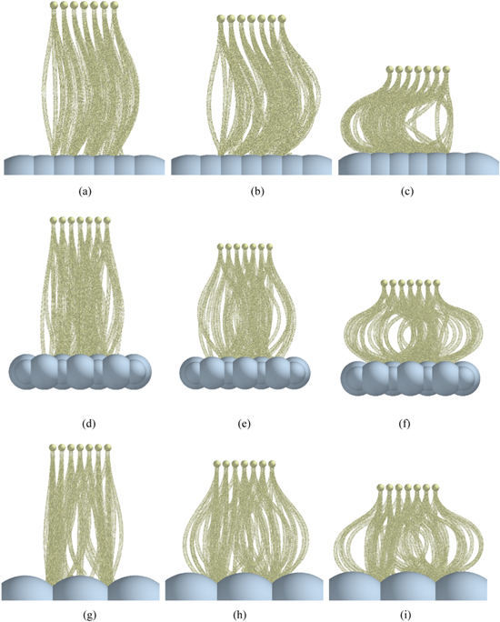
Figure 9. Carbon nanotube arrays attached onto rough contact surfaces. (a) Preload = 100 nm, peak-to-valley spacing of 6 nm. (b) Preload = 250 nm, peak-to-valley spacing of 6 nm. (c) Preload = 500 nm, peak-to-valley spacing of 6 nm. (d) Preload = 100 nm, peak-to-valley spacing of 50 nm. (e) Preload = 250 nm, peak-to-valley spacing of 50 nm. (f) Preload = 500 nm, peak-to-valley spacing of 50 nm. (g) Preload = 100 nm, peak-to-valley spacing of 160 nm. (h) Preload = 250 nm, peak-to-valley spacing of 160 nm. (i) Preload = 500 nm, peak-to-valley spacing of 160 nm.
Download figure:
Standard image High-resolution imageAfter normal unloading, the carbon nanotube array was stretched away from the rough contact surface in both normal and tangential directions, respectively. The effect of preloading on the adhesion of carbon nanotube arrays was simulated.
Figure 10 depicts adhesion force curves obtained by normal and tangential desorption, where the carbon nanotube array was on a rough contact surface with a maximum peak-to-valley spacing of 6, 50, and 160 nm. The initial preload amounts were set to 100, 250, and 500 nm, respectively.
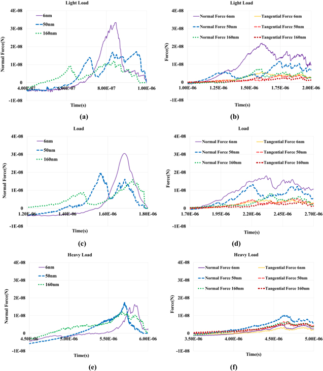
Figure 10. Carbon nanotube array force curves with a rough contact surface. (a) Normal motion with 100 nm preloading distance. (b) Tangential motion with 100 nm preloading distance. (c) Normal motion with 250 nm preloading distance. (d) Tangential motion with 250 nm preloading distance. (e) Normal motion with 500 nm preloading distance. (f) Tangential motion with 500 nm preloading distance.
Download figure:
Standard image High-resolution imageThe maximum adhesion of the carbon nanotube arrays under each parameter was summarized, and the data obtained is listed in table 3. The relationship between normal adhesion of the carbon nanotube array and the preloading and contact surface roughness is shown in figure 11. The relationship between the tangential adhesion of the carbon nanotube array and the pre-stress and contact surface roughness is shown in figure 12.
Table 3. Maximum adhesive force by simulation with a variety of microarray parameters.
| Adhesion force of carbon nanotubes (N) (0.35 μm × 0.35 μm = 1.225 × 10⁻⁹ cm2) | |||||
|---|---|---|---|---|---|
| Peak-to-valley distance (μm) | Detaching direction | Adhesion force | Preload = 100 nm | Preload = 250 nm | Preload = 500 nm |
| 0.006 | Normal | Normal | 3.34 × 10⁻⁸ N | 3.04 × 10⁻⁸ N | 1.62 × 10⁻⁸ N |
| Tangential | Normal | 2.19 × 10⁻⁸ N | 1.79 × 10⁻⁸ N | 0.49 × 10⁻⁸ N | |
| Tangential | 0.55 × 10⁻⁸ N | 0.45 × 10⁻⁸ N | 0.33 × 10⁻⁸ N | ||
| 0.05 | Normal | Normal | 1.68 × 10⁻⁸ N | 1.97 × 10⁻⁸ N | 1.63 × 10⁻⁸ N |
| Tangential | Normal | 1.17 × 10⁻⁸ N | 1.32 × 10⁻⁸ N | 1.03 × 10⁻⁸ N | |
| Tangential | 0.41 × 10⁻⁸ N | 0.48 × 10⁻⁸ N | 0.65 × 10⁻⁸ N | ||
| 0.16 | Normal | Normal | 1.19 × 10⁻⁸ N | 1.57 × 10⁻⁸ N | 1.16 × 10⁻⁸ N |
| Tangential | Normal | 0.74 × 10⁻⁸ N | 0.82 × 10⁻⁸ N | 0.65 × 10⁻⁸ N | |
| Tangential | 0.26 × 10⁻⁸ N | 0.37 × 10⁻⁸ N | 0.56 × 10⁻⁸ N | ||
| 0.006 | Normal | Normal | 27.27 N cm−2 | 24.82 N cm−2 | 13.22 N cm−2 |
| Tangential | Normal | 17.88 N cm−2 | 14.61 N cm−2 | 4.00 N cm−2 | |
| Tangential | 4.49 N cm−2 | 3.67 N cm−2 | 2.69 N cm−2 | ||
| 0.05 | Normal | Normal | 13.71 N cm−2 | 16.08 N cm−2 | 13.31 N cm−2 |
| Tangential | Normal | 9.55 N cm−2 | 10.78 N cm−2 | 8.41 N cm−2 | |
| Tangential | 3.35 N cm−2 | 3.92 N cm−2 | 5.31 N cm−2 | ||
| 0.16 | Normal | Normal | 9.71 N cm−2 | 12.82 N cm−2 | 9.47 N cm−2 |
| Tangential | Normal | 6.04 N cm−2 | 6.69 N cm−2 | 5.31 N cm−2 | |
| Tangential | 2.12 N cm−2 | 3.02 N cm−2 | 4.57 N cm−2 | ||

Figure 11. Curve of normal adhesion with preload and contact surface roughness.
Download figure:
Standard image High-resolution image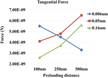
Figure 12. Curve of tangential adhesion with preload and contact surface roughness.
Download figure:
Standard image High-resolution imageBased on table 3 and figures 11 and 12, the variation in the maximum adhesion force of the carbon nanotube array was summarized, and the following conclusions were obtained:
- 1.The purpose of preloading is to enable the CNTS to overcome the influence of roughness and make more CNTS end to surface contact to increase adhesion. On the micro rough surface, a small amount of preloading brought the ends of the carbon nanotube array in contact with the surface. Therefore, increasing the prepressure will only make the array of carbon nanotubes become irregular and reduce the adhesion. The normal and tangential adhesion forces of the carbon nanotube array decreased with an increase in the amount of preloading.
- 2.On a rough surface, the normal adhesion force increased at first, and then decreased with an increase in the amount of preloading. Because, suitable normal preloading increased the contact area of the end of the carbon nanotube array with the rough surface, which increased the adhesion force. However, excess preloading would cause the carbon nanotube array to become irregular, affecting the amount of carbon nanotubes involved in adhesion. The tangential adhesion force of the carbon nanotube array increased with an increase in the amount of preloading. Because excess preloading increase the resistance of carbon nanotube arrays in horizontal motion.
- 3.Roughness could have a negative impact on the normal adhesion force of the carbon nanotube array. For the same amount of preload, the normal adhesion force decreased with an increase in roughness. As the amount of preloading increased, the negative impact of roughness on the normal adhesion gradually reduced.
- 4.For light preloading, roughness had a negative effect on the tangential adhesion force of the carbon nanotube array, and the tangential adhesion force decreased with an increase in roughness. As the amount of preloading increased, the roughness had a positive effect on the tangential adhesion force. The tangential adhesion force increased at first, and then decreased with the increase of the roughness.
3.3. Experimental study on adhesion characteristics of multiwalled carbon nanotube arrays
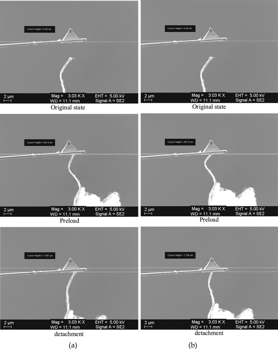
Test the adhesion force of a single group of carbon nanotube arrays by a micro force test platform with AFM. By pre-pressing, the ends of the carbon nanotube arrays were brought in contact with the surface of AFM cantilever, and then the normal preload was removed. Finally, the carbon nanotube array was separated from the surface of the object by normal stretching. The normal adhesion forces of the carbon nanotube array during the detachment process were obtained by the deformation of the AFM cantilever, and the adhesion characteristics were analyzed. Figure 13 show the normal desorption processes of the carbon nanotube array in microscopically.
Figure 13. Normal desorption process of the carbon nanotube array (a) Preload = 104.5 nm. (b) Preload = 257.6 nm.
Download figure:
Standard image High-resolution image
Based on the test process above, the normal preloading was divided into 104.5 and 257.6 nm. The influence of preload on the adhesion characteristics of a single group of carbon nanotubes was then analyzed experimentally. The maximum adhesion of a single group of carbon nanotubes array under each preload was summarized, and the data obtained are listed in table 4.
Table 4. Maximum adhesive force obtained by experiment with a variety of microarray parameters.
| Adhesion force of carbon nanotubes (N) (d = 0.4456 μm, S = 0.156 μm2) | ||
|---|---|---|
| Preloading deformation | 104.5 nm | 257.6 nm |
| Preload force | 2.09 nN | 5.15 nN |
| Adhesion deformation | 1.067 μm | 1.104 μm |
| Adhesion force | 21.34 nN | 22.08 nN |
| Adhesion pressure | 13.68 N cm−2 | 14.15 N cm−2 |
Then Test carbon nanotube array adhesion property from macroscopically. The contact surface was divided into two types: smooth glass and frosted glass. The roughness of smooth and frosted glass is 1.6 and 0.05 μm. The normal preloading was divided into 100, 250, and 500 mN. Three experiments were performed for each parameter, and the average was taken. The influence of preloading and contact surface roughness on the adhesion characteristics of carbon nanotubes was then analyzed experimentally. The maximum adhesion of the carbon nanotubes under each parameter was summarized, and the data obtained are listed in table 5.
Table 5. Maximum adhesive force obtained by experiment with a variety of microarray parameters.
| Adhesion force of carbon nanotubes (5 mm × 2 mm = 10 mm2) | |||||
|---|---|---|---|---|---|
| Contact surface | Detaching direction | Adhesion force | Preload = 100 mN | Preload = 250 mN | Preload = 500 mN |
| Smooth glass | Normal | Normal | 0.125 N | 0.165 N | 0.180 N |
| 0.130 N | 0.170 N | 0.190 N | |||
| 0.115 N | 0.155 N | 0.180 N | |||
| Tangential | Normal | 0.085 N | 0.105 N | 0.110 N | |
| 0.070 N | 0.115 N | 0.120 N | |||
| 0.095 N | 0.100 N | 0.125 N | |||
| Tangential | 0.035 N | 0.040 N | 0.045 N | ||
| 0.040 N | 0.035 N | 0.055 N | |||
| 0.035 N | 0.040 N | 0.060 N | |||
| Frosted glass | Normal | Normal | 0.070 N | 0.105 N | 0.125 N |
| 0.060 N | 0.110 N | 0.130 N | |||
| 0.075 N | 0.120 N | 0.125 N | |||
| Tangential | Normal | 0.050 N | 0.055 N | 0.060 N | |
| 0.065 N | 0.070 N | 0.055 N | |||
| 0.060 N | 0.065 N | 0.055 N | |||
| Tangential | 0.035 N | 0.050 N | 0.055 N | ||
| 0.040 N | 0.045 N | 0.060 N | |||
| 0.050 N | 0.050 N | 0.075 N | |||
| Smooth glass | Normal | Normal | 1.23 N cm−2 | 1.63 N cm−2 | 1.83 N cm−2 |
| Tangential | Normal | 0.83 N cm−2 | 1.07 N cm−2 | 1.18 N cm−2 | |
| Tangential | 0.37 N cm−2 | 0.38 N cm−2 | 0.53 N cm−2 | ||
| Frosted glass | Normal | Normal | 0.68 N cm−2 | 1.12 N cm−2 | 1.27 N cm−2 |
| Tangential | Normal | 0.58 N cm−2 | 0.48 N cm−2 | 0.58 N cm−2 | |
| Tangential | 0.42 N cm−2 | 0.50 N cm−2 | 0.63 N cm−2 | ||
The experimental data were analyzed and compared with the simulation results, and the following conclusions were drawn:
As for the carbon nanotube array adhesion property from microscopically. The adhesion characteristics of a single group of carbon nanotube arrays under vacuum conditions were measured by AFM, and it was concluded that with the increase of pre-stress, the adhesion force of carbon nanotubes array was increased, but the trend was small.
As for the carbon nanotube array adhesion property from macroscopically. For both smooth glass and frosted glass, the adhesion force per unit area of the tested carbon nanotube array was smaller than that obtained by simulation. Moreover, both normal adhesion and tangential adhesion of the carbon nanotube array increased with an increase in the amount of preloading. When the carbon nanotube array adhered to the frosted glass, the tendency of adhesion was obvious with an increase in the amount of preloading. This phenomenon was believed to occur because the processed carbon nanotube array contained nanotubes of different lengths, resulting in a decrease in adhesion. Therefore, preloading is required to increase the contact area, thereby increasing the adhesion.
Roughness had a negative impact on the normal adhesion force of the carbon nanotube array. In the case of the same amount of preloading, the normal adhesion force decreased as the roughness increases. As the amount of preloading increased, the negative impact of roughness on the normal adhesion force of the carbon nanotube array gradually reduced. In the case of light preloading, the roughness had a negative effect on the tangential adhesion force of the carbon nanotube array, and the tangential adhesion force decreased with an increase in the roughness. As the amount of preloading increased, the roughness had a positive effect on the tangential adhesion force of the carbon nanotube array. The tangential adhesion force increased at first, and then decreased with an increase in roughness. The experimental results of the roughness effect on adhesion were consistent with the simulation results.
4. Conclusions
This section is not mandatory, but can be added to the manuscript if the discussion is unusually long or complex.
In this study, the adhesion technology of a space crawler robot was studied, and a carbon nanotube array structure was adopted as the adhered nanoscale microarray structure of the robot foot. A theoretical model of the carbon nanotube structure was established, and the influence of structural parameters of the carbon nanotube array on its adhesion characteristics was analyzed. The maximum adhesion of carbon nanotubes was seen to decrease with an increase in chiral angle. A force model of carbon nanotube arrays on surfaces with different roughness and under different preloads was established by using the discrete element software, EDEM. Simulation of the desorption process of the carbon nanotube array structure in normal and tangential directions was conducted. The adhesion characteristics of the carbon nanotube structure were analyzed. Results showed that roughness had a negative impact on the normal adhesion force of the carbon nanotube array. The tangential adhesion force of the carbon nanotube array increased with an increase in the amount of preloading. The normal adhesion force increased at first, and then decreased with an increase in the amount of preloading.
On this basis, a carbon nanotube microarray structure was fabricated by using chemical vapor deposition, and a micro force test system was established on the platform of a scanning electron microscope to test the adhesion force of a single group of carbon nanotube arrays in a vacuum environment. And also a two-dimensional force test platform which test carbon nanotube array adhesion property from macroscopically was established.
The influence of preloading and roughness on the adhesion characteristics of the carbon nanotube array structure was analyzed. In this paper, the adhesion of carbon nanotubes measured by simulation and experiment is less than that of carbon nanotubes array measured in the reference. Because the focus of this paper is not to optimize the design of carbon nanotubes array, but to analyze the adhesion characteristics of the end of the vertical carbon nanotubes array in contact with the surface of the object, and to analyze the influence of pre-pressure and roughness on the adhesion characteristics. Results demonstrated that, whether on smooth glass or frosted glass, the adhesion of the tested carbon nanotube array per unit area was smaller than that obtained by simulation. Moreover, both normal adhesion and tangential adhesion of the carbon nanotube array increased with an increase in the amount of preloading. When the carbon nanotube array adhered to the frosted glass, the tendency of adhesion was obvious with an increase in the amount of preloading. The reason for this phenomenon was the different lengths of nanotubes present in processed carbon nanotube array, which resulted in a decrease in adhesion. Therefore, preloading was required to increase the contact area, thereby increasing the adhesion. As a key to achieving the function of adhesion and crawling of space robots, these research results will provide strong support for space-on-orbit maintenance missions.
Funding
This research was funded by The National Nature Science Foundation of China (Grant No. 51575123, 61673287); The CAT-BISEE fund of the Beijing institute of spacecraft environment engineering (Grant No. 2017-024); Support by self-Planned Task (No.SKLRS201801B) of State Key Laboratory of Robot Technology and System (HIT) and the Fundamental Research Funds for the Central University (Grant No. HIT. NSRIF. 2017028) and the Pre-research project for manned space flight (17520306).
Conflicts of interest
The authors declare no conflict of interest.