

Abstract
Flexible three-dimensional interconnected carbon nanotubes on the carbon cloth (3D-CNTs/CC) were obtained through simple magnesium reduction reactions. According to the Nernst equation, the cell voltage based on these pure carbon electrodes without any additives could reach 1.5 V due to the higher di-hydrogen evolution over potential in neutral 3.5 M LiCl electrolytes. In order to improve the electrochemical performance of the electrodes, 3D-CNTs/CC electrodes covered with polyaniline barrier layer (3D-PANI/CNTs/CC) were prepared by in situ electropolymerization using interfacial engineering method. The assembled symmetric supercapacitors display a broadened voltage of 1.8 V, high areal capacitance of 380 mF cm−2, outstanding areal energy density of 85.5 μWh cm−2 and 84% of its initial capacitance after 20 000 charge-discharge cycles. This work demonstrated that the interface engineering strategy provides a promising way to improve the energy density of carbon-based aqueous supercapacitors by widening the voltage and boosting the capacitance simultaneously.
Export citation and abstract BibTeX RIS
1. Introduction
With the rapid development of portable electronic devices and electric vehicles, energy storage devices are meeting more rigorous performance requirements to satisfy large-scale practical applications. Compared with the strict moisture-free conditions for the construction of alkali metal ion batteries, aqueous supercapacitors (AqSCs) have received extensive attention due to their high power density, long cycle lifetime, and high safety [1–3]. However, the energy density of AqSCs is smaller than the battery because of the inherent low voltage of AqSCs due to the low thermodynamic stability of water (1.23 V). According to the energy density formula of E = 1/2CV2, simultaneously increasing the specific capacitance (C) and expanding the voltage (V) of the device are promising approaches to boost the energy density (E) [4].
Undoubtedly, the electrodes, as the key components of the supercapacitors (SCs), make a significant contribution to the electrochemical performance of the device [5–7]. Carbon cloth (CC) and other carbon-based textile fabrics have been widely employed as an electrode or a substrate owing to their outstanding mechanical strength [8], low cost, and high flexibility. However, the CC electrode shows poor areal capacitance provided by the electrical double-layer capacitance (EDLC) because of the small specific surface area of carbon-based textile fabrics materials. Therefore, several approaches have been proposed to improve the electrochemical performance of carbon electrodes [9]. Directly activating the materials [6, 10, 11] could effectively enhance the surface area of activated CCs, such as via chemical exfoliation leading to increased areal capacitance (76 mF cm−2) of the device in 1 M H2SO4 aqueous solution at the scan rate of 10 mV s−1 [10]. Apart from that, combined with high specific surface area carbon materials [12, 13] or pseudo-materials with CC-based composite materials are another efficient methods to obtain high capacitance of the electrode [5, 14–20]. For example, introducing PANI, an all-hydrogel supercapacitor implant based on PANI@rGO/Mxenes electrode and hydrogel electrolyte was obtained, and it occupied high-performance, biocompatibility, conformal adhesion, and mechanical compatibility with soft tissues [21]. However, it is a remarkable fact that the stable electrochemical window of the aforementioned devices is limited at 1.0 V in the aqueous electrolyte [4, 6, 11], which is caused by undesirable water decomposition [22]. Hence, under the premise of improving the capacitance of the electrode, enlarging the voltage of SC is an effective way to improve the energy density of AqSCs according to the energy density formula.
To design high voltage AqSCs, introducing barrier layers or occupying the specific functional groups on the surface of carbon-based materials by preadsorption of alkali metals has attracted considerable attention owing to the inhibited water splitting of aqueous electrolytes, which is a promising strategy of surface engineering on the electrodes [3, 4]. Consequently, the operating voltage of the device is remarkably broadened from 1.3 to 1.8 V through optimizing the oxygen-containing functional groups of porous carbon cloth by an assistant of the physical barrier with adsorbing Na+ [6]. While easily surface engineering by coating conductive polymers on the electrode surface are rarely used as barrier layers compared with their pseudo-capacitance behavior.
Excepting for surface engineering on the electrode, pH regulation of electrolytes is an alternative way to widen the electrochemical stability window of aqueous electrolytes [23, 24]. In general, the practical potential window of H2SO4 and KOH electrolytes on porous carbon electrodes is usually less than 1 V due to the thermodynamic limit of water reduction [25, 26]. In comparison, the larger potential window of the device based on the porous carbon in neutral aqueous electrolytes or hybrid ion supercapacitors could reach up to 1.8 V or even 2.0 V (such as 2 mol l−1 Li2SO4 [26], 1 mol l−1 Na2SO4 [27], 1 mol l−1 LiNO3 [28] or Zn ion hybrid supercapacitor [29]). Therefore, the synergistic effect of simultaneously boosting the capacitance of electrodes and broadening the voltage of SCs to improve energy density is of high interest for further investigation.
In this work, a simple two-step strategy was applied to design a flexible 3D-PANI/CNTs/CC composite electrode with engineering surface by combining the high surface area CNTs and pseudo-capacitance material of PANI, which could not only enhance the capacitance but also improve electrochemical stability window of electrolyte owing to the elimination the surface group of CNTs by in situ coating PANI. The symmetric SC assembled with 3D-CNTs/CC in the neutral LiCl electrolyte could reach 1.5 V due to higher di-hydrogen evolution over-potential according to the Nernst equation. The high areal capacitance of 535 mF cm−2 at 1 mA cm−2 was ascribed to high mass loading and interconnected CNTs. When PANI was used as the barrier layer, the voltage of AqSCs was significantly broadened from 1.5 to 1.8 V, further depressing the activity of hydrogen evolution due to the decreasing surface group of O–C=O/C–O by covering the PANI on the surface of 3D-CNTs. In addition, its areal capacitance was improved simultaneously due to the pseudo-capacitance behavior of PANI. Thanks to the synergistic effect, the AqSCs assembled with 3D-PANI/CNTs/CC electrodes displayed a high areal capacitance of 760 mF cm−2 at 1 mA cm−2, a high areal energy density of 85.5 μWh cm−2 at 0.45 mW cm−2 (around twice of that for 3D-CNTs/CC), and an ultrastable, long cycle life with capacitance retention of 84% after 20 000 cycles.
2. Experimental section
2.1. Materials synthesis
Ni(NO3)2·6H2O (ACS Reagent, >98%), Al(NO3)3·9H2O (ACS Reagent, >98%), Ethanol, Aniline, H2SO4, HCl, Mg power were directly used without further purification. Commercial carbon cloth (W0S1009, 0.33 mm in thick, CeTech Co., Ltd) was used as the supporting material for growing 3D-CNTs. The carbon cloth was cleaned by ultrasonication in acetone, ethanol, and deionized water for 30 min, respectively. Then it was washed several times with deionized water and dried thoroughly at 60 °C for 24 h in a vacuum oven. The density of the cleaned carbon cloth (CC) is about 12.6 mg cm−2.
2.1.1. Preparation of the catalyst solution
Typically, 581.6 mg of Ni(NO3)2·6H2O and 75 mg of Al(NO3)3·9H2O were added to a 40 ml ethanol solution and stirred at room temperature for 2 h to obtain a clear green solution. Then, CC was impregnated with the catalyst ethanol solution for 20 min subsequently, CC was taken out from the solution and dried in an oven at 60 °C for 30 min.
2.1.2. Catalysts reduction and 3D-CNTs growth
As reported in our previous work [30], the 3D-CNTs in the carbon cloth (3D-CNTs/CC) were prepared by the magnesiothermic reduction method with some modifications. Firstly, 1.5 g Mg powers were uniformly spread out in the middle of the alundum (Al2O3) boat (20 × 60 × 90 mm3), and a piece of CC (3 × 3 cm2) coated with the catalyst precursor was put on the Mg powers. Secondly, the boat was put into the middle of a horizontal tube furnace (Φ 70 × 1000 mm, HLZG-16B, LUOYANG HENG LI FURNACE KILN CO., LTD, China) filled with Ar/H2 gas atmosphere at a flow of 50 SCCM (standard cubic centimeters per minute). The furnace was heated to the desired temperature of 800 °C. During the temperature-rise period, the catalyst precursor was converted into catalyst nanoparticles, and then the temperature was kept at 800 °C for 1 h to melt the Mg power sufficiently. After that, CO2 flowed at 50 SCCM and was kept at 0.5 h to obtain the 3D-CNTs. During the reaction stage, CO2 was deoxidized by Mg, and the 3D-CNTs were synthesized directly on the surface and interconnected to the gap of CC. When the reaction finished, CO2 gas flowing was turned off, and the furnace was cooled down to room temperature under Ar/H2 gas atmosphere. 3D-CNTs/CC was achieved after etching the NiO, MgO and Al2O3 away using a 3 M HCl aqueous solution for one day. Then, the obtained 3D-CNTs/CC were slightly washed several times with deionized water until the PH of the solution was neutral and dried thoroughly at 60 °C for 24 h in a vacuum oven. The average mass loading of the 3D-CNTs on CC is 6 mg cm−2.
2.1.3. Preparation of polyaniline on 3D-CNTs/CC (3D-PANI/CNTs/CC)
The 3D-PANI/CNTs/CC was prepared via in situ electropolymerization method [31]. In a three-electrode system, Ag/AgCl electrode, Pt sheet, and 3D-CNTs/CC electrode were used as the reference electrode, counter electrode, and working electrode, respectively. And the electrolyte was a 1 M H2SO4 solution with 0.1 M aniline monomers. The polyaniline was grown on the 3D-CNTs/CC by cyclic voltammetry at 5 mV s−1 from −0.3 to 0.9 V versus Ag/AgCl for 1 and 3 cycles. After the electrodeposition, the 3D-PANI/CNTs/CC hybrid composites were washed with deionized water and dried at 60 °C for 24 h in a vacuum oven. For convenience, the electrodes were named 3D-PANI/CNTs/CC-1cycle, and 3D-PANI/ CNTs/CC-3cycles, respectively.
2.2. Characterization of the electrode materials
The morphology of the electrodes was observed by scanning electron microscope (SEM, Hitachi, S-4800) and transmission electron microscope (TEM, Tecnai G2 F20). The surface electronic states of the electrodes were investigated by using x-ray photoelectron spectrometer (XPS, Thermo Scientific, K-Alpha+). The chemical constituents were characterized by Raman spectroscopy (LabRAM HR Evolution, 532 nm YAG laser). And Fourier transforms infrared (FTIR) spectra were recorded on Infrared spectroscopy-Infrared microscopy (Thermofisher, IS50) on KBr pellets.
2.3. Electrochemical measurements and calculation of the areal capacitances of the symmetric supercapacitors
The symmetric supercapacitors were constructed using 3D-CNTs/CC or 3D-PANI/CNTs/CC as the electrode and 3.5 M LiCl aqueous solution as the neutral electrolyte. 3D-CNTs/CC and 3D-PANI/CNTs/CC were cut into 1 × 1 cm2. The electrochemical properties of the samples were evaluated by performing the cyclic voltammetry (CV), galvanostatic charge-discharge (GCD), and electrochemical impedance spectroscopy (EIS) tests, which were collected by an electrochemical workstation (CHI 660E, Chenhua). Especially, cycling stability was measured by GCD tests with the macro-command. EIS tests were measured over a frequency range of 10 mHz∼100 kHz at the open-circuit potential.
The potential ranges of the samples used as positive or negative electrodes were detected by a CV curve at the scan rate of 1 mV s−1 in a three-electrode system, in which the sample (1 × 1 cm2), the platinum plate, and Ag/AgCl electrode were used as the working electrode, the counter electrode, and the reference electrode, respectively.
For the symmetric supercapacitors, the areal capacitance of the cell was calculated from the GCD profiles according to the following equation [32]:
The capacitance of the cell:

The areal capacitance of the single electrode:

where I (mA) is the discharge current, Δt (s) is the discharge time, ΔV (V) is the potential window of the discharge process, and A (cm2) is the active area of the two electrodes face to face.
The areal energy density EA, and areal power density PA were calculated according to the following equations:


3. Results and discussion
3.1. Preparation and structure characterization of the electrodes
3D-PANI/CNTs/CC flexible composite electrode was designed to enhance the energy density of devices by combining the high surface area CNTs and pseudo-capacitance material of PANI, which also could improve the electrochemical stability window of the electrolyte on this electrode because the surface group of CNTs was covered by in situ coating PANI as the barrier layer. The synthetic process of the composite electrode is schematically illustrated in figure 1(a). Firstly, the ultra-long carbon nanotubes with an average diameter of 500 nm were directly grown on the surface of CC textile by using the magnesiothermic reduction reaction [33–36]. Then, a layer of PANI was coated uniformly on the surface of 3D-CNTs/CC via a simple electropolymerization process. Figures 1(b) and (e) show the initial state of the CC consisting of interweaving carbon fibers with an average diameter of 10 μm, where the surface of the fibers is smooth, leading to a small specific surface area and less contribution to the capacitance [11]. In comparison, after the magnesiothermic reduction reaction, the abundant ultra-long CNTs with the interconnected structure are evenly enwrapped on the surface of carbon cloth (figures 1(c), (f)). Furthermore, as shown in figure S1, the morphology of 3D-CNTs/CC changed obviously. At the same time, the 3D-CNTs/CC electrode is stable enough to be bent without sacrificing the mechanical properties due to the strong interaction between the active materials and substrate, which is better than 3D-CNT foam that was reported in our early works [33, 34]. In addition, the average loading mass of the 3D-CNTs on CC is about 6 mg cm−2, which is higher than traditional powdered-based active materials.
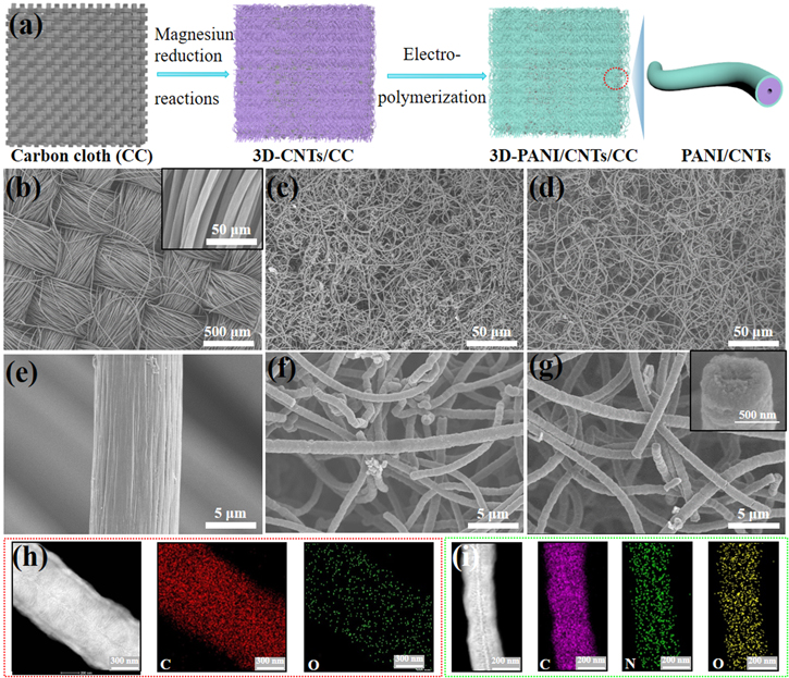
Figure 1. (a) Schematic illustration of the synthetic process of 3D-PANI/CNTs/CC. SEM images of (b), (e) CC, (c), (f) 3D-CNTs/CC, and (d), (g) 3D-PANI/CNTs/CC. The insets in figures 1(b) and (g) are the corresponding high-magnification SEM images of CC and one single CNT of 3D-PANI/CNTs/CC, respectively. TEM image and elemental mapping image of a single CNTs (h) without and (i) with a coating of PANI, respectively.
Download figure:
Standard image High-resolution imageTo further improve the electrochemical performance of the 3D-CNTs/CC electrode, the surface engineering of the binder-free electrode was implemented by using in situ electropolymerization of PANI on the surface of CNTs. Firstly, PANI was polymerized by cyclic voltammetry at a scan rate of 5 mV s−1 from −0.3 to 0.9 V versus Ag/AgCl for 1 and 3 cycles, respectively, in order to obtain the optimum electropolymerization parameter. SEM images presented in figure S2 clearly show that the amount of obtained PANI increased obviously with the polymerization cycles. However, much more PANI aggregates on the gap of 3D-CNTs with increasing the polymerization up to 3 cycles, which may block the electron transfer [31] and increase the impedance of electrodes as shown in figure S3. Thus, the optimal 3D-PANI/CNTs/CC electrode was obtained by selecting the polymerization of aniline for 1 cycle. Due to the excellent conductivity of the electrode, PANI nanoparticles are enwrapped uniformly on the surface of the 3D-CNTs (figures 1(d) and (g)). The corresponding high magnification SEM of single CNT with a coating of PANI is shown in the inset of figure 1(g). The 3D interconnected structures can provide more charge transfer paths and shorten ion transport distance, enabling to improvement of the electrochemical performances of electrode materials [37]. To further investigate the microstructure, TEM images of single CNT without and with a coating of PANI are shown in figures 1(h) and (i), revealing that the CNTs exhibit blood-like hierarchical structures, which is similar to observed for CNT prepared by similar magnesiothermic reduction reaction method [38, 39]. Based on N2 isothermal adsorption-desorption measurements (figure S4), the specific surface area of 3D-CNTs/CC electrode (249.2 m2 g−1) is higher than CC substrate (<10 m2 g−1) [10, 11], indicating that the effective surface activity site would be increased. In addition, the oxygen element presented in figure 1(h) suggests that some oxygen-containing functional groups exist in 3D-CNTs/CC. In comparison, the elemental mapping images shown in figure 1(i) demonstrate the presence of the N element generates from the PANI barrier layer after surface engineering. Moreover, the N element is a uniform distribution on the CNTs, indicating that PANI is well-deposited on the surface of 3D-CNTs/CC. The high percentage of N-doped will improve the capacitance performance of composites due to the pseudo-capacitance nature of PANI.
Raman spectra of different electrodes were analyzed to study the influence of electropolymerization cycles on the formation of PANI, as shown in figure 2(a). The 3D-CNTs/CC electrodes display two prominent D (1330 cm−1) and G band (1589 cm−1), which is arose from sp2 and sp3/sp2 hybridized carbon atoms, respectively [40, 41]. The intensity ratio of D and G bands (ID /IG) of 3D-CNTs/CC calculated based on the intensity of D and G peak at 1330 and 1589 cm−1 is about 1.09, proving the existence of the defect and disordered carbon structure in the 3D-CNTs [6]. After electropolymerization for 1 cycle, peaks located at 1164 cm−1 (C–H bending of the quinoid rings) and 1472 cm−1 ( C=N of the quinone diimine structure) of the composite come from the PANI [42], while the typical peaks of G and D bands weaken evidently compared with 3D-CNTs, manifesting that PANI is uniformly coated on the surface of 3D-CNTs. As the number of polymerization cycles increases to 3 cycles, the intensity of these two peaks is much higher than that of 1 cycle, especially for C=N stretching vibration (1472 cm−1). It demonstrates that much more PANI is synthesized not only on the surface of CNTs but also in the gap of CC, which is in good agreement with the previous SEM results. Consequently, the oxygen-containing functional groups from 3D-CNTs/CC are covered by PANI, which acts as the barrier layer to probably broaden the potential window of electrolyte. In addition, the tightly contact between PANI and CNTs will be facilitated the electron transport between the interfaces, resulting in good charge propagation.
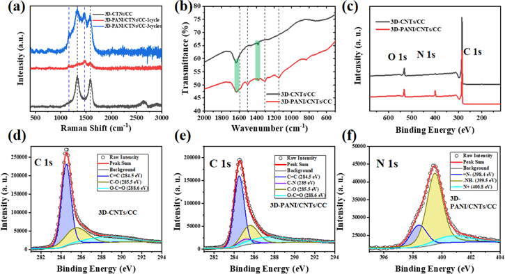
Figure 2. (a) Raman spectrum of 3D-CNTs/CC, 3D-PANI/CNTs/CC with electropolymerization of 1 cycle and 3 cycles; (b) ATR-FTIR spectra of 3D-CNTs/CC and 3D-PANI/CNTs/CC; (c) XPS spectra of 3D-CNTs/CC, and 3D-PANI/CNTs/CC; (d) High-resolution C 1s spectrum of 3D-CNTs/CC; High-resolution (e) C 1s spectrum and (f) N 1s spectrum of 3D-PANI/CNTs/CC.
Download figure:
Standard image High-resolution imageInterfacial bonding of the PANI layer was revealed by FTIR analysis. FTIR spectra of 3D-PANI/CNTs/CC and 3D-CNTs/CC are shown in figure 2(b). Clearly, the two characteristic peaks that appeared at 1387, 1636 cm−1 correspond to O–H (carboxyl) and C=O (carboxylic acid), respectively, suggest that 3D-CNTs/CC contains a number of oxygenated functionalities during magnesiothermic reduction process [43, 44]. The carboxylic acid that existed at the surface of CNTs would give rise to the electrolyte decomposition [45]. After the surface modification with PANI, the surface groups of the CNTs were tailored. The oxygenated functionalities of 3D-PANI/CNTs/CC are slightly reduced compared with the 3D-CNTs/CC (marked in figure 2(b) with a green rectangle). At the same time, the FTIR spectrum of 3D-PANI/CNTs/CC exhibits several new typical peaks (marked in figure 2(b) with a black dash line) belonging to the coated PANI [19]. The peak of N-Q-N stretching vibration locates at 1145 cm−1, which is a characteristic peak of PANI [46]. The peak located at 1306 cm−1 corresponds to the C–N stretch of the secondary aromatic amine of PANI chains [47]. Apart from that, the peaks located at 1593 cm−1 and 1505 cm−1 are assigned to the C=C stretching vibration of the quinoid rings and benzenoid rings of the polymer backbone in PANI, respectively. All in all, the several new peaks indicate that PANI is successfully in situ polymerized on the surface of 3D-CNTs/CC, which is consistent with the Raman results.
The chemical composition of the samples was analyzed by x-ray photoelectron spectroscopy (XPS). The full XPS spectra of 3D-CNTs/CC and 3D-PANI/CNTs/CC are shown in figure 2(c). It can be seen that the characteristic peaks at 284.8 eV, 400.3 eV and 532.5 eV are assigned to C 1s, N 1s, and O 1s, respectively. As shown in figure 2(d), the high-resolution spectrum of C 1s of 3D-CNTs/CC can be deconvoluted into three peaks, suggesting the presence of C=C bonding (284.5 eV), C–O bonding (285.5 eV), and O–C=O bonding (288.6 eV), respectively [48, 49]. After PANI deposition, except for the above-mentioned three bands on the surface of CNTs, a new peak at 285 eV (C–N bonding) [50] was demonstrated in the high-resolution spectrum of C 1s of 3D-PANI/CNTs/CC (figure 2(e)), confirming the polymerization of PANI on 3D-CNTs/CC successfully, which is consistent with the SEM and TEM analysis. From the high-resolution N 1s spectra of 3D-PANI/CNTs/CC (figure 2(f)), the peaks at 398.4 eV, 399.5 eV and 400.8 eV correspond to the quinoid imine (=N−), benzenoid imine (−NH−), and positively charged imine (N+) of N 1s, respectively. Additionally, the nitrogen-containing functional groups increase more, and the abundant quinoid imine (−N=) enhances the electron delocalization, ensuring high conductivity of the 3D-PANI/CNTs/CC electrode [51] and contributing additional pseudo-capacitance to the total capacitance. Furthermore, the XRD patterns of 3D-CNTs/CC and 3D-PANI/CNTs/CC are shown in figure S5. Two typical diffraction peaks of these two samples appeared at about 26.0° and 42.7° correspond to the (002) and (100) planes of CNTs, respectively.
3.2. Determination of the optimized working potential windows (WPW) of neutral electrolyte on the electrodes
To broaden the voltage of SCs as large as possible, 3.5 M neutral LiCl aqueous solution was selected as the electrolyte. Cyclic voltammetry measurements were performed to evaluate the electrochemical stability of the aqueous electrolytes by estimating the electrochemical properties of the positive and negative electrodes, respectively. Figure 3(a) shows the CV curves of bare CC (black), 3D-CNTs/CC (blue), and 3D-PANI/CNTs/CC (red) electrodes at 1 mV s−1 in a three-electrode system, using Ag/AgCl and Pt plate as the reference and counter electrode, respectively. The CV curves of 3.5 M LiCl on the 3D-CNTs/CC and 3D-PANI/CNTs/CC electrode with near rectangular shape are presented in the positive polarization potential 0 to 0.7 V versus Ag/AgCl. However, the rectangular shape of CV maintains at negative polarization potential of 0 to −0.8 versus Ag/AgCl and 0 to −1.1 versus Ag/AgCl for 3D-CNTs/CC and 3D-PANI/CNTs/CC electrode, respectively. In contrast, the CV curve on the bare CC electrode (the enlarged view shown in figure S6) in the same electrolyte is negligible, indicating that there is no capacitance contribution to the 3D-CNTs/CC and 3D-PANI/CNTs/CC electrode. In addition, the obtained negative polarization potential of the 3D-CNTs/CC was lower than the equilibrium potential for hydrogen evolution, which could be ascribed to the neutral LiCl electrolyte, where the nascent hydrogen was absorbed in the micropores of 3D-CNTs during the water reduction process. Consequently, the concentration of hydroxyl OH- anions generated in the porosity of the electrode is higher than that in the bulk electrolyte, leading to a local pH increase in the pores of the micro/mesoporous hierarchical carbon electrode. Finally, the Nernst hydrogen evolution potential was lower than that of water decomposition [52]. For 3D-PANI/CNTs/CC electrode, the negative window becomes wider than the 3D-CNTs/CC electrode owing to the presence of the barrier layer of PANI in the outer surface of CNTs, decreasing surface group of O–C=O/C–O inhibiting the HER process. Furthermore, the CV curve of 3D-PANI/CNTs/CC exhibits a larger area, resulting in the improved capacitance of electrodes owing to the high mass loading of 3D-CNTs and the pseudo-capacitance behavior of PANI simultaneously.
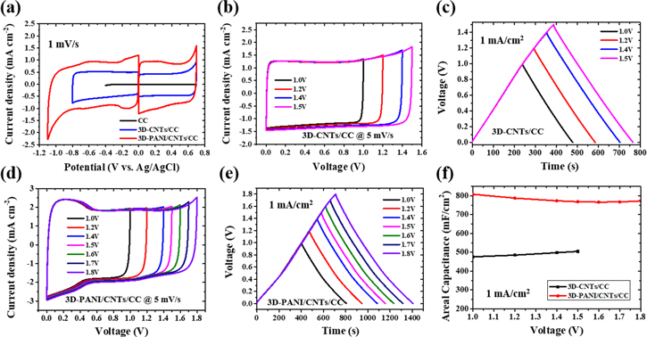
Figure 3. Electrochemical behaviors of the electrodes in LiCl electrolyte. (a) CV curves of different electrodes as positive or negative electrodes in a three-electrode system at 1 mV s−1, respectively. (b) CV curves with different potential windows of 3D-CNTs/CC in a two-electrode system at 5 mV s−1. (c) GCD curves with different potential windows of 3D-CNTs/CC in a two-electrode system at 1 mA cm−2. (d) CV curves with different potential windows of 3D-PANI/CNTs/CC in a two-electrode system at 5 mV s−1. (e) GCD curves with different potential windows of 3D-PANI/CNTs/CC in a two-electrode system at 1 mA cm−2. (f) The areal capacitance of the cells at 1 mA cm−2 at different voltages for 3D-CNTs/CC and 3D-PANI/CNTs/CC, respectively.
Download figure:
Standard image High-resolution imageThe electrochemical performance of symmetrical capacitors based on 3D-CNTs/CC and 3D-PANI/CNTs/CC electrodes were investigated by recording CV curves at 5 mV s−1 and the GCD curves at 1 mA cm−2 in a two-electrode system. As expected, the symmetric SCs assembled with 3D-CNTs/CC electrodes maintained typical rectangular shapes in the CV curves and nearly triangular shapes in the GCD curves with linear slopes at different voltages up to 1.5 V (figures 3(b) and (c)), suggesting the superior ion transport behavior. It indicates that these symmetrical SCs based on 3D-CNTs/CC electrodes in LiCl neutral electrolyte could reach up to 1.5 V, which is comparable with the reported carbon-based capacitors in the aqueous electrolyte [10, 11, 39, 53, 54]. In figures 3(d) and (e), it can be clearly recognized that the CV curves of symmetric SCs assembled with 3D-PANI/CNTs/CC in 3.5 M LiCl changed dramatically with appearing of one pair of redox peaks at around 0.2 V, which is ascribed for the pseudo-capacitance behavior of PANI. Moreover, these CVs always retained a rectangle-like shape until 1.8 V, which is attributed to the barrier layer of PANI between electrodes and electrolyte. Meanwhile, the GCD curves at different voltages up to 1.8 V are nearly symmetric with two different slopes, which is well consistent with the CV curves. This means the Faraday pseudocapacitive nature of PANI can be present in the neutral electrolyte due to the doping/de-doping of Cl-. Due to the PANI barrier layer suppressing the hydrogen evolution, the higher capacitance of the cell based on the 3D-PANI/CNTs/CC electrode with larger voltage is obtained, indicating that the surface-engineered PANI layer on the 3D-CNTs/CC plays a vital role in boosting the energy density with enlarging the voltage range and improving the capacitance simultaneously (figures 3(f), S7). This study further proves the feasibility of the surface engineering method with PANI.
3.3. Electrochemical performance of symmetric capacitors in neutral electrolyte
The electrochemical performance of the devices based on 3D-CNTs/CC and 3D-PANI/CNTs/CC using the neutral electrolyte in the voltage of 1.5 V and 1.8 V were studied systematically, respectively. As shown in figure 4(a), the CV curves still exhibit a rectangular shape under the different scan rates up to 100 mV s−1, demonstrating a good EDLC performance. The small current leap appears close to V = 1.5 V at 5 mV s−1, which is attributed to the reversible chemisorption of hydrogen in the porosity of the negative electrode [55]. When the scan rate increase, this current leap become not evident because of the fast reversible chemisorption of hydrogen. GCD curves show the symmetric charge/discharge features at different current densities from 1 to 20 mA cm−2, indicating that the capacitor based on the 3D-CNTs/CC electrode exhibits a good charge propagation (figure 4(b)). In contrast, figure 4(c) shows CV curves of the 3D-PANI/CNTs/CC-based devices at scan rates from 5 to 100 mV s−1 at the voltage of 1.8 V. When increasing the scan rate, there is no obvious polarization even at a high rate of 100 mV s−1, revealing the high rate capabilities of the device on 3D-PANI/CNTs/CC electrode in neutral LiCl electrolyte. Meanwhile, there are two redox peaks existing in the CV curves, which are attributed to the pseudo-capacitance behavior of PANI during doping and de-doping of Cl- ions. The presence of redox peaks from 3D-PANI/CNTs/CC-based devices results in higher capacitance than that of 3D-CNTs/CC. As shown in figure 4(d), the triangle shapes of those GCD curves still keep symmetric with the current density increase from 1 to 20 mA cm−2, indicating its outstanding capacitance behavior and good charge propagation.

Figure 4. (a) CV curves of the capacitor based on 3D-CNTs/CC electrode with different scan rates. (b) GCD curve of the capacitor based on 3D-CNTs/CC electrodes with different current densities. (c) CVs of the capacitor based on 3D-PANI/CNTs/CC electrodes with different scan rates. (d) GCD curve of the capacitor based on 3D-PANI/CNTs/CC electrodes with different current densities. (e) The areal capacitance of the cells on the different current densities of GCD. (f) Ragone plots for the 3D-CNTs/CC and 3D-PANI/CNTs/CC-based SCs, and other recently reported carbon-based SCs.
Download figure:
Standard image High-resolution imageAccording to GCD profiles in figures 4(b) and (d), the areal capacitances of the device based on the single 3D-CNTs/CC electrode are 535, 520, 508, 492, 457 and 397 mF cm−2 corresponding to the current density of 1, 2, 3, 5, 10, 20 mA cm−2, respectively, suggesting its good rate capability and capacitance retention of near 74.3%. Compared with other reported carbon-based electrode [10, 11, 39, 53, 54], it is noted the areal capacitances are boosted due to the high mass loading and its high voltage in neutral electrolyte. Benefitting from the 3D structures, the electrodes not only avoid aggregation but also provide efficient ion transport pathways. When surface engineered with PANI, the areal capacitances of the device based on the single 3D-PANI/CNTs/CC electrode (760 mF cm−2 at 1 mA cm−2) are higher than 3D-CNTs/CC (535 mF cm−2 at 1 mA cm−2) at the same current density, as shown in figure 4(e). Even the current density reaches up to 20 mA cm−2, the areal capacitance of 571 mF cm−2 still could be delivered, demonstrating excellent rate capability of the capacitor based on 3D-PANI/CNTs/CC electrode. Additionally, the corresponding areal energy densities of the devices were calculated and presented in figure 4(f). Ragone plots showed an ultra-high areal energy density of 85.5 μWh cm−2 (based on two electrodes) with a maximum power density of 0.45 mW cm−2, which is approximately twice than that of 3D-CNTs/CC (41.8 μWh cm−2, 0.375 mW cm−2), revealing its outstanding energy storage capability. Moreover, it is higher than other similar works (such as plasma-activated CC, PANI/GO/CC, PANI/graphene/cotton yarn, PANI array on CC, integrated paper consisting of cellulose fibers, activated carbon and carbon black) [11, 17, 53, 56, 57].
At the low-frequency region in figure S3, the Nyquist plot of the 3D-CNTs/CC-based cell almost parallels the imaginary axis, confirming the typical capacitive nature in the LiCl electrolyte. After coating PANI, the slight deviation for the cells is attributed to the poor conductivity of the polymer. Compared with 3D-PANI/CNTs/CC cells, the reduced semicircle of 3D-CNTs/CC-based cell demonstrates good contact between the 3D carbon electrode and the current collectors. Based on the high-frequency region magnified in the insets, the values of the equivalent series resistance (ESR), and charge transfer resistance (Rct) of different cells were estimated [55], where the ESR of the cell based on 3D-CNTs/CC, 3D-PANI/CNTs/CC-1cycle, and 3D-PANI/CNTs/CC-3cycles are 4.9, 5.05 and 4.6 Ω, respectively. And the Rct of them are 0.2, 0.18 and 0.55 Ω, respectively. With increasing the polymerization cycle number, the Rct of the cells increases due to decreasing conductivity of the PANI, and the small Rct of 3D-PANI/CNTs/CC-1cycle cell means the fast electron transport and ions adsorption/desorption processes, which unveils the synergistic effect of PANI in improving the interface of the electrode and electrolyte, and simultaneously boosting the capacitance of electrodes and broaden the voltage of SCs, effectively.
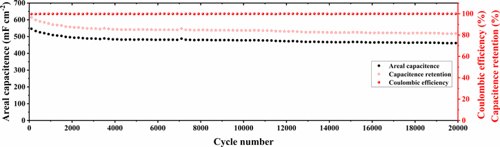
The cycle stability is a very important factor for practical application, where the cycling stability of the device base on 3D-PANI/CNTs/CC electrode was measured at a high current density of 10 mA cm−2 at the voltage of 1.8 V. As shown in figure 5, the device delivers a high areal capacitance of 460 mF cm−2 and maintains 84% of its initial capacitance after 20 000 cycles, implying excellent stability. Furthermore, it also should be pointed out that the coulombic efficiency is always maintained at approximately 100%, further proving that PANI-engineered 3D-CNTs surface is electrochemically stable for long-term operation. All in all, it demonstrates that the free-standing 3D-PANI/CNTs/CC electrode reveals excellent electrochemical performance with an ultrahigh voltage of 1.8 V.
Figure 5. The cycle stability of 3D-PANI/CNTs/CC electrode.
Download figure:
Standard image High-resolution image
4. Conclusions
In summary, we have demonstrated an effective strategy to improve the energy density of the AqSCs by enlarging the voltage and boosting the capacity simultaneously. The 3D-CNTs/CC electrode was fabricated by the green magnesiothermic reduction method. Due to ultra-long interconnected, high surface area, and high mass loading, when assembled to symmetric supercapacitors, the high areal capacitance of 535 mF cm−2 at 1 mA cm−2 was obtained, and the voltage can reach 1.5 V in neutral electrolyte. To further improve the electrochemical performance of the 3D-CNTs/CC electrode, the surface is engineered with the PANI. After introducing the PANI layer, the voltage of aqueous symmetric SC was significantly broadened from 1.5 to 1.8 V, and the areal capacitance was boosted to 760 mF cm−2 at 1 mA cm−2 simultaneously. The main reasons for the excellent performance are as follows: (a) PANI layer as a physical barrier changes the surface oxygen-containing functional group of CNTs. (b) the pseudocapacitive nature of PANI in the neutral electrolyte. Thank to the synergistic effect between electrode and electrolyte, 3D-PANI/CNTs/CC electrode provides a high areal energy density of 85.5 μWh cm−2 at 0.45 mW cm−2 (a twofold increase than 3D-CNTs/CC) and an ultrastable, long cycle life with capacitance retention of 84% after 20 000 cycles. This work helps understand the energy storage process of the 3D-PANI/CNTs/CC electrode and further provides a strategy to obtain ultrahigh voltage AqSCs.
Acknowledgments
This work was supported by the National Natural Science Foundation of China (Grant Numbers 11874317, U2004174), Natural Science Foundation of Henan Province (Grant Number 202300410330), Excellent Research Project for Overseas Students in Henan Province, and the Nanhu Scholars Program for Young Scholars of XYNU. This work used the instruments in the Analysis & Testing Center of Xinyang Normal University.
Data availability statement
The data that support the findings of this study are available upon reasonable request from the authors.
Author contributions
Zhichao Ji: Conceptualization, Methodology, Supervision, Writing-original draft, Writing-review & editing, Funding acquisition. Congcong Liu: Data curation. Wenhe Xie: Visualization. Shenghong Liu: Visualization. Chao Zhang: Visualization. Fuwei Liu: Visualization. Haibin Sun: Visualization. Yang Lu: Visualization. Xuexue Pan: Writing-review & editing. Chunlei Wang: Project administration, Writing-review & editing. Zhuanpei Wang: Validation, Visualization, Writing-review & editing.
Conflicts of interest
There are no conflicts to declare.
Supplementary data (0.5 MB PDF)