


Abstract
Focusing on the stable magnification, near zero distortion, and wide field of depth (DoF), the telecentric optical system is well suited for size measurements with a large range of working distances. However, suffering from the telecentricity-based error (TBE), the size measurement is connected with the working distances and imaging position of the image sensor, even within the DoF. Therefore, a model of TBE compensation is established, inspired by the radial distortion model in the camera calibration. With the correction of radial distortion coefficients for different working distances, the TBE is evidently improved. The feasibility of the proposed method is verified both in the theory and experiment. Our results show that the uncertainty of size measurement at different working distances of the DoF is improved obviously after the TBE compensation, which is attractive for fine size measurements in industry.
Export citation and abstract BibTeX RIS
1. Introduction
Combinations of optical imaging, machine design, motion control and image processing, and machine vision technology have the advantages of non-contact, high accuracy and fast processing, which makes it popular for fine measurement and detection in industry [1–8]. Hu et al measured the thickness and profile of transparent material using a fluorescent stereoscopic microscope [9]. George et al measured the size of various objects in endoscopic images by machine vision [10]. Xu et al monitored the deformation of bridge rope based on machine vision technology [11]. Zu et al designed an optical measuring instrument, and measured the multi-dimensional parameters of a diamond cutter [12]. Jia et al proposed an extrinsic calibration method for multiple RGB-D cameras in a limited field of view, and achieved high calibration accuracy [13].
As one of the key technologies, optical imaging captures the object information directly and contributes most to the measurement accuracy. Usually, a high resolution is required in the optical system to get more details for the measured object. However, higher resolution means a narrower field of depth (DoF). A narrower DoF might not be suitable for size measurement for different working distances. Furthermore, the magnification changes with the working distance in the non-telecentric lens, resulting in the measurement error. In contrast, a telecentric lens offers a high resolution, near zero distortion, a wide DoF, and a stable magnification, which is popular for size measurement [1, 14, 15]. Schuster et al respectively analyzed the influence of distortion and perspective errors in non-telecentric and telecentric lenses, showing that the telecentric lens can achieve higher accuracy [16]. Pan et al compared the images respectively captured by the non-telecentric and telecentric lenses, showing that the telecentric lens could get a sub-pixel accuracy, although the measured object is not on the center plane [17]. Tian et al established the telecentric-based calibration model, and achieved excellent accuracy [18]. This conclusion can also be verified in their measurement system, with three dimensions using the telecentric imaging theory [19].
An absolute fine measurement result is obtained for the telecentric lens, especially for objects having different measured planes. For telecentric optical systems, a stable magnification is designed for the DoF, benefitting from the design of parallel rays in theory. This indicates that the parameters of camera calibration in one plane of the DoF can be used in the whole DoF, and achieve a high accuracy of size measurement. However, because of the manufacturing and assembly errors in the telecentric lens, the chief rays and the optical axis have a small angle in reality, which is called telecentricity. Affected by the telecentricity, the image sizes of the same object at different working distances or imaging positions have a tiny difference, resulting in the measurement errors [20]. The typical value of the telecentricity is 0.1°, which will cause a measurement error of 17 μm when the object moves 10 mm along the optical axis. This cannot meet the requirement for the fine size measurement. It is necessary to compensate for the measurement error caused by the telecentricity. Generally, the camera calibration for the telecentric lens is also aimed at one measuring plane, having no connection with the working distance [21, 22]. In our previous work, a linear model between the magnification and working distance was established to compensate for the telecentricity-based error (TBE) [23]. The influence of telecentricity was improved in the whole DoF. In this model, the TBE depends only on the working distance, and ignores different imaging positions for the same working distance. In this paper, a new model of the TBE compensation is established, inspired by the radial distortion model, considering both the working distance and imaging position.
2. Telecentricity analysis
The perspective error is efficiently avoided when the lens is telecentric on the image side, object side, or both sides. The accuracy of the size measurement is improved. Figure 1 shows the telecentric optical imaging system, mainly composed of a telecentric lens, camera and measured object. In the telecentric optical system, the measured object has a constant magnification at different imaging positions in theory. As shown in figure 2, an aperture stop is added at the nominal focal point to ensure that the chief rays are always parallel to the optical axis, and the magnification is constant in the whole DoF. However, the aperture stop does not always fully coincide with the nominal position after assembly of all the components of the telecentric lens, resulting in a small deviation between the chief rays and the optical axis. This tiny angle between the chief rays and the optical axis is called telecentricity. Suffering from the telecentricity, the magnification slightly changes with the different working distance, which affects the measurement accuracy even within the DoF. As shown in figure 2, the measured objects L0, L1, and L2 with the same length at different working distances have different image sizes in the DoF. As a result, the telecentric lens also exits the best working distance, similar to the non-telecentric lens. This position is defined as the center plane, as shown in figure 1. Taking the telecentricity into consideration, using the constant parameters of camera calibration of the center plane to the whole DoF is not enough for the fine size measurement. Therefore, it is necessary to establish a model of TBE compensation to improve the measurement accuracy for the telecentric lens.
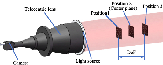
Figure 1. Imaging process analysis of telecentric optical system.
Download figure:
Standard image High-resolution image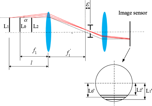
Figure 2. Telecentricity analysis.
Download figure:
Standard image High-resolution image3. System analysis
3.1. TBE compensation model
For a telecentric lens, the telecentricity is constant after assembly. Our experiment recently showed that the measurement uncertainty caused by the telecentricity not only depends on the working distance, but also is related to the imaging position of the image sensor. Therefore, inspired by the radial distortion model of camera calibration, a model of TBE compensation is established, as shown in equation (1)
where δx and δy are the deviation amounts caused by the telecentricity error along the x and y directions, respectively. (x, y) and (xd, yd) are the image coordinates before and after the TBE compensation, respectively. The compensation parameters c1 and c2 are connected with the deviation amount Δl between the working plane and calibrated plane, which can be fitted by the polynomial shown in equation (2)
where, a1i a2i (i=1, 2,...n1) are the fitting coefficients of the polynomial. Three steps following are implemented to compensate for the TBE.
- (a)Camera calibration on one working plane to obtain the camera parameters, including the distortion parameters.
- (b)Corrections of the radial distortion parameters using equation (2) for different deviations between the working plane and calibrated plane.
- (c)Updating the distortion parameters and compensating the TBE.
3.2. Center plane
As mentioned above, the first step is camera calibration for the TBE compensation. Obviously, high accuracy of camera calibration is necessary for the fine size measurement. Giving attention to the telecentricity, the telecentric optical system also has a best sharpness plane, just like the focal plane of the non-telecentric lens. This plane is therefore used as the calibration plane, which is defined as the center plane, as shown in figure 1. Many methods of image sharpness evaluation were proposed [24–26]. Among them, the gradient sharpness function has the advantage of a low computing complex [27, 28], and is expressed as:
where, i(x, y) is the gray intensity for pixels (x, y). m and n are the numbers of rows and columns, respectively. The mean gray intensity differences between pixels (x, y) and (x−1, y), (x, y−1) are respectively computed. The values are then accumulated to compute the sharpness value S, combining the number of pixels. The plane with the largest S is the center plane.
3.3. Camera calibration
The telecentric lens-based camera calibration technologies have been studied by many scholars [18, 21, 29, 30]. Using the orthogonal projection, the coordinate of an arbitraries point P can be expressed as:
When considering the radial, centrifugal and thin-prism distortions, we have:
where k1 and k2 are the coefficients of radial distortion. p1 and p2 are the coefficients of centrifugal distortion. s1 and s2 are the coefficients of thin-prism distortion. (xu, yu) and (u, v) are the image and pixel coordinates, respectively. The pixel coordinate (u0, v0 ) denotes the position of the original point O. du and dv are pixel sizes of the x and y directions, and m is the magnification. ri (i = 1−4) are the parameters of the rotation matrix R, and tx, ty are the parameters of translations. (Xw, Yw, Zw) denotes the world coordinate of point P.
4. Experiment
To verify the feasibility of the proposed method, a measurement experiment of TBE compensation was implemented. As presented in figure 3, the experimental devices mainly include a telecentric lens, light source, translation device, calibration plate and computer. The types and parameters of the partial devices are shown in table 1.
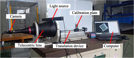
Figure 3. Measurement devices.
Download figure:
Standard image High-resolution imageTable 1. Parameters of experimental devices.
| Type | Parameters | |
|---|---|---|
| Camera | MV-EM510C | Pixel number and size: 2456 × 2058, 4.4 μm |
| Telecentric lens | BT-23144 | Magnification: 0.061, DoF:90 mm |
| Translation device | FLS30 | Range: 300 mm, Accuracy: 0.05 mm |
| Calibration plate | GP070-12*9 | Square size and numbers: 5 mm, 12 × 9 |
First, the translation device is moved with a step of 1 mm to roughly find the position of the best sharpness image. A series of images were captured and the sharpness values of images are computed according to equation (3). The position of the best sharpness value is the center plane, stating in section 3.2. As shown in figure 4, the 68th image has the best sharpness, which is defined as the center plane (z = 0 mm). With a step of 1 mm, the images from the position of the whole DoF were captured, setting the center plane as the middle plane, and 90 images were obtained. The camera calibration is implemented in the center plane, and the results are shown in table 2
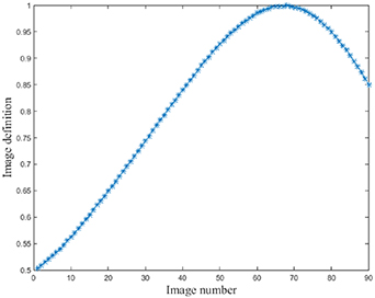
Figure 4. Image sharpness analysis.
Download figure:
Standard image High-resolution imageTable 2. Parameters of camera calibration.
| Magnification m ×10−2 | Origin (u0, v0) | [k1, k2, p1, p2, s1, s2] ×10−5 |
|---|---|---|
| 6.3650 | (1228.00,1028.98) | [5.425, −1.072, 0.910, 1.957, −1.006, −1.930] |
According to the results of table 2 and equation (1), a nonlinear optimization was performed to get the coefficients of TBE compensation. The results are shown in figure 5, and the curve functions are fitted using the quadratic polynomials, as shown in equation (7)
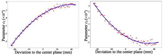
Figure 5. Values of telecentricity parameters.
Download figure:
Standard image High-resolution imageAs shown in figure 6, eight horizontal measured lengths and six vertical measured lengths on the calibration plate are chosen to verify the feasibility of the proposed method. The results are shown in figures 7 and 8. The red points and blue stars in each sub-figure of figures 7 and 8 denote the measured sizes before and after the TBE compensation for different working distances, respectively. The RMSE comparison for the whole DoF is presented in Tables 3 and 4. For the horizontal measured lengths (nominal value is 50 mm), the measurement uncertainty is decreased from 35.3 μm to 4 μm on the whole DoF after the TBE compensation. For the vertical measured lengths (nominal value is 35 mm), the measurement uncertainty is decreased from 19.3 μm to 3.8 μm on the whole DoF after the TBE compensation. It is obvious that the measurement uncertainty caused by the telecentricity is well compensated by the proposed method, and the measurement accuracy of the whole DoF is improved perfectly.
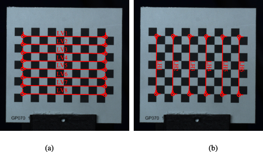
Figure 6. Measured lengths for the (a) horizontal and (b) vertical directions.
Download figure:
Standard image High-resolution image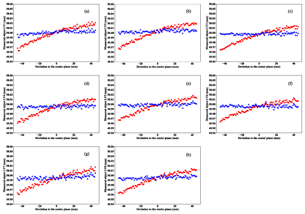
Figure 7. Results comparison for the horizontal measured lengths before and after TBE compensation (red and blue points are the measurement values before and after the compensation).
Download figure:
Standard image High-resolution image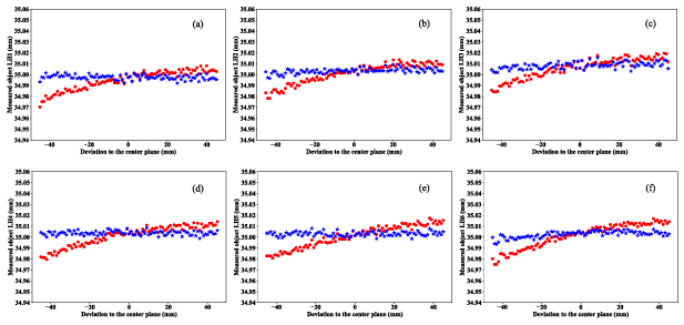
Figure 8. Results comparison for the vertical measured lengths before and after TBE compensation (red and blue points are the measurement values before and after the compensation).
Download figure:
Standard image High-resolution image
Table 3. Measurement uncertainty corresponding to figure 7 (mm).
| LV1 | LV2 | LV3 | LV4 | LV5 | LV6 | LV7 | LV8 | Mean value | |
|---|---|---|---|---|---|---|---|---|---|
| BC a | 0.0321 | 0.0318 | 0.0353 | 0.0392 | 0.0330 | 0.0368 | 0.0368 | 0.0373 | 0.0353 |
| AC a | 0.0033 | 0.0015 | 0.0014 | 0.0063 | 0.0014 | 0.0059 | 0.0058 | 0.0060 | 0.004 |
aBC and AC are before compensation and after compensation of the TBE, respectively.
5. Conclusion
In this paper, we analyze the influence of the measurement uncertainty caused by the telecentricity in the telecentric optical system. Inspired by the radial distortion of camera calibration, a model of TBE compensation is established for different working distances and different imaging positions away from the center of distortion. For different working planes, the coefficients of radial distortion are corrected, and the measurement uncertainty caused by the telecentricity is improved. The feasibility of the proposed method has been verified both in the theoretical and experimental analysis. The measurement accuracy is improved over the whole DoF, which is attractive for measured objects with heights in the industry.
Acknowledgments
The authors would like to appreciate the financial support from Guangxi Science and Technology Base and Special Talents Program (2018AD19077), Guangxi Key Laboratory of Manufacture System & Advanced Manufacture Technology (No. 17-259-05-009z), and Guangxi Innovation and Driving Development Special Funds Project (No. AA18118002-3).
Data availability statement
The data that support the findings of this study are available upon reasonable request from the authors.
Conflict of interest
None.