

Abstract
Electronics, which harnesses the properties of electrons, has made remarkable progress since its inception and is a cornerstone of modern society. Ionics, which exploits the properties of ions, has also had a profound impact, as demonstrated by the award of the Nobel Prize in Chemistry in 2019 for achievements related to lithium-ion batteries (LIBs). Ionic conduction in solids is the flow of carrier ions through a solid owing to an electrical or chemical bias. Some ionic materials have been studied intensively because their ionic conductivities are higher than those of liquids, even though they are solids. Among various conductive species, fluoride ions are the most promising charge carriers for fluoride-ion batteries (FIBs) as post LIBs. Increasing fluoride-ion conductivity toward the superionic conductive region at room temperature would be a breakthrough for the room-temperature operation of all-solid-state FIBs. This review focuses on fluoride-ion conductors, from the general concept of ions to the characteristics of fluoride ions. Fluoride-ion conductors are classified according to material type and form, and our current understanding, identification of problems, and future directions are discussed from experimental and theoretical physics perspectives.
Export citation and abstract BibTeX RIS
1. Introduction
Figure 1(a) shows a schematic of electronic conductivity with electrons as the conducting species. Materials can be classified as insulators that do not conduct electricity, semiconductors that exhibit intermediate conductivity, good conductors (metals) that conduct electricity, and superconductors that exhibit superconductivity. Insulators, such as natural rubber and polyvinyl chloride, are widely used as coatings for insulating electronic devices and cables. Semiconductors, such as silicon and germanium, are used in transistors, diodes, and integrated circuits, and are fundamental to modern life. Metals, such as iron, copper, and tin, are shiny and ductile, and also exhibit the high electrical and thermal conductivity. They are abundant in our environment. In addition, under a high pressure of 300 GPa, almost all pure elements, except some inert gases, exhibit metallic conduction [1]. Details of the electronic properties of metals can be found in textbooks [2]. Semimetals include arsenic and antimony, and they are used in drugs and industrial materials. Superconductivity is the disappearance of electrical resistance. In 1911, during Onnes's work in cryogenics, he measured the conductivity of metals at very low temperatures, resulting in the discovery of superconductivity [3]. In 1986, the first of the cuprate superconductors, which are superconductive at liquid nitrogen temperature, was discovered [4], and their practical applications have increased steadily since then. More recently, room-temperature superconductivity in hydrides under high pressure has been reported [5].

Figure 1. Comparison of (a) electronic and (b) ionic conductivity. (c) Similarities and differences in ions and electrons.
Download figure:
Standard image High-resolution imageIon diffusion, in which ions are the conducting species, is a universal phenomenon in chemistry, biology, and physics. Ionic conduction is not as diverse as electronic conduction and the ionic conductivity is generally lower than the electronic conductivity (figure 1(b)). Ionic conductors have a long history, with high ionic conductivity reported by Faraday in silver chalcogens [6]. At the end of the 19th century, Nernst created a luminescent material [7], which consisted of zirconia (ZrO2), and an oxygen-ion conductor, marking the beginning of the use of superionic conductors. The discovery of ionic conduction in solid AgI sparked research into ionic conduction in other solids [8]. AgI exhibits unusual behavior, in which the ionic conductivity of the solid phase is higher than that of the liquid phase.
AgI is classified as a type I intrinsic superionic conductor that undergoes a first-order transition at high temperatures. PbF2, which has a fluorite structure, is classified as a type II intrinsic superionic conductor. Above 712 K, it undergoes a Faraday transition in which the F configuration changes, but the Pb backbone lattice is retained, and it then shows a high fluoride-ion conductivity [9]. In contrast, yttria-stabilized zirconia is an extrinsic superionic conductor, in which the substitution of tetravalent Zr with trivalent Y creates oxygen vacancies [10].
Nevertheless, superionic conductivity in solids is only in the semiconductive range for electronic conductors because ions are larger and heavier than electrons (figure 1(c)). However, according to string theory, both electrons and nuclei are ultimately made from strings, and thus there are similarities between these particles. Zero ion resistance (ionic superconductivity) has not yet been discovered.
1.1. General design guidelines for ionic conductors
The general design guidelines for ionic conductors are as follows.
- (1)Many sites should be occupied by mobile ions and these ions should be able to occupy empty sites.
- (2)Ion diffusion pathways should be present.
- (3)The diffusion pathways should be of a size suitable for mobile ions.
- (4)The difference in potential energy between occupied and empty sites should be small.
- (5)The polarizability of mobile ions or component ions should be large.
Guideline (1) is directly related to the carriers. The ion diffusion pathways in guideline (2) can be one-dimensional (1D), two-dimensional (2D), or three-dimensional (3D), and diffusion tends to be faster in lower-dimensional systems. In guideline (3), the size of the diffusion pathway should be optimized for the mobile ions. Guideline (4) corresponds to optimizing the size of the potential energy difference, which is a bottleneck. Guideline (5) implies that mobile or skeletal ions should be easily distorted.
The 14 ions reported as the main conduction species are shown in blue in figure 2. It is intuitive to imagine that monovalent ions have higher mobility because the energy at the equilibrium position is determined by the Coulomb interaction, which is proportional to the charge of the moving ion. Lithium ions are charge carriers in lithium-ion batteries (LIBs) and are the ions responsible for charging and discharging. Multivalent ions tend to form covalent bonds, and a large amount of energy is required to overcome this energy. Oxide-ion conductors have attracted attention as solid electrolytes for fuel cells. Materials that satisfy all the requirements for electrolytes, of high ionic conductivity, high electrochemical stability, high chemical stability, low synthesis cost, and mass production, are hard to find. Elements that form the framework of crystals are shown in green in figure 2. These are highly oxidation-reduction-resistant elements and include inexpensive and expensive elements.

Figure 2. Periodic table classified by general ionic conduction species (blue) and skeletal elements (green) of solid electrolytes.
Download figure:
Standard image High-resolution image1.2. Synthetic approach
Synthetic approaches to target materials can be classified into four broad categories described in the following subsubsections. The material must contain elements that serve as charge carriers. Solid electrolytes must exhibit electron insulation and a stable potential window in addition to ionic conductivity. Therefore, elements that satisfy these requirements must be used as other cations. For example, early transition metal ions in the first and second rows, such as Ti4+, Zr4+, Nb5+, and Ta5+, have no electrons in their d-orbitals, preventing electronic conduction. Other candidates are group 13 ions such as Al3+ and Ga3+, group 14 ions such as Si4+ and Ge4+, and group 15 ions such as P5+.
1.2.1. Elemental substitution of existing materials.
Elemental substitution of existing materials is a basic, reliable method. In this method, ionic conductivity is improved by considering the ionic radius and the valence state based on the periodic table to control the number of carriers, the polarizability, and the size of bottleneck. The framework atoms in the material have already been selected, and the physical properties can be improved. For example, the ionic conductivity can be increased by two to eight orders of magnitude in lithium-ion conductors [11]. Materials with compositions that are more complex can be developed using this approach. For example, binary compounds can be altered to obtain ternary and quaternary compounds.
1.2.2. Composition-based searches.
Composition-based searches are difficult because the composition and skeletal structure are not determined. However, unexpected new compositions have been discovered and developed as solid electrolytes. For example, by systematically changing the composition between Li4GeS4 and Li3PS4, thio-LISICON with an analogous structure was discovered [12]. For materials with unknown structures, the initial structural model is generally extracted by single-crystal x-ray diffraction or real space methods. The crystal structure is then refined by powder x-ray diffraction measurements.
1.2.3. Structure-based searches.
Structure-based searches begin with the selection of the skeleton in the structure, which often relies on the intuition and experience of the researchers. Perovskite and garnet structure solid-state electrolytes were developed from mineral crystal structures. The structures of materials that mimic the natural world or that are used in other fields are useful references, and beautiful structures often harbor functionality. For example, it was difficult to synthesize layered cathode materials, such as CoO2 and NiO2, which have similar structures to TiS2. However, research focused instead on a layered low-dimensional 2D magnetic material, LiMO2 (M = V, Cr, Co, Ni), containing lithium ions. The LIB cathode material, Lix CoO2, was created based on the idea that if lithium ions could be reversibly extracted and inserted from these oxides electrochemically, it would function as a cathode with high electromotive force [13].
1.2.4. Exploration using theoretical methods.
A wide array of theoretical and computational approaches to battery modeling has been developed, encompassing different length and time scales of the operation of battery materials. Most of this research has focused on LIBs, but these methods are also applicable to fluoride-ion batteries (FIBs). Materials informatics, which combines materials science and information science, has led to the discovery of natural laws, accelerated materials development, and higher precision in measurements and observations. There has been much research on screening materials and proposing new materials based on the physical properties obtained from calculations and experiments. An effective method is to use structural descriptors that are highly correlated with the ionic conductivity based on knowledge of crystalline materials, build predictive models based on these descriptors, and screen candidate materials from a database. The screening is refined further by highly accurate first-principles calculations, and materials are then proposed. Lithium-ion conductors and oxide-ion conductors have been proposed by virtual screening, and have been confirmed experimentally as good ionic conductors. Theoretical prediction of structure and composition using computational science and machine learning is attractive for exploring new materials not found in the database, although it is unclear whether they can be synthesized. In addition, the predictions do not provide information on the synthesis method, and the synthesis conditions must be explored experimentally and optimized. Although this is the method most likely to produce new ideas, whether the materials can be synthesized depends strongly on the synthesis technique.
1.3. Ion diffusion mechanism
Ion diffusion in crystals occurs via the vacancy, interstitial, and quasi-interstitial mechanisms (figure 3). In the vacancy mechanism, ions simply move into vacancies. In the interstitial mechanism, conducting ions move through gaps in a polyhedron composed of ions with opposite charges. In this case, the barrier potential, which serves as a bottleneck, must be lowered to achieve the high conductivity. In the quasilattice mechanism, multiple ions move cooperatively.

Figure 3. Ion diffusion based on (a) the vacancy mechanism, (b) the interstitial mechanism, and (c) the quasi-interstitial mechanism. Dotted and filled circles denote the ions before and after diffusion, respectively.
Download figure:
Standard image High-resolution imageTable 1 lists the main ionic conductive species [14]. In general, cations diffuse more readily than anions because cations are often smaller. Monovalent ions, such as H+, H−, F−, Na+, K+, Cu+, and Ag+, and divalent Mg2+ and O2− ions are the conductive species. Monovalent ions tend to exhibit higher ionic conductivity than divalent ions.
Table 1. Conductive ionic species and their ionic radii.
| Ion | Ionic radius (nm) |
|---|---|
| Li+ | 0.060 |
| O2– | 0.140 |
| F– | 0.133 |
| Na+ | 0.095 |
| Mg2+ | 0.065 |
| Cl– | 0.181 |
| Cu+ | 0.096 |
| Br– | 0.196 |
| Ag+ | 0.126 |
The ionic conductivity is

where Ze is the charge of the conducting species, n is the amount of carrier, and μ is the mobility. Vacancies or interstitials are treated as the mobile charged species and μ describes the ability of these species to move through the solid lattice. μ is related to diffusion coefficient D by the Nernst–Einstein relation,

where kB is the Boltzmann constant and T is the absolute temperature. In addition, μ can be written as
where τ is the relaxation time and m* is the effective mass. Therefore, for controlling ionic conduction, the carrier mass, mobility, diffusion coefficient, and effective mass are the main factors. The carrier density and mobility of superionic conductors and semiconductors with nearly identical conductivity are compared. The carrier density of superionic conductors is several orders of magnitude larger, whereas their mobility is several orders of magnitude smaller.
Ionic conductivity with an activation energy is written as

where A is the pre-exponential factor and E is the activation energy. A and E can be evaluated by plotting the measured temperature and conductivity, with 1/1000 T on the horizontal axis and log σ on the vertical axis. A can be written as
where ΔSm is the entropy of migration, α0 is the hopping distance, and ν0 is the hopping frequency. z is a constant and depends on the directionality of the conduction mechanism (figure 4) [15]. E is a factor that characterizes ionic conductors, which often have small values below 0.2 eV for superionic conductors.

Figure 4. Energy profiles associated with cation migration via (a) direct vacancy or interstitial hopping and (b) correlated hopping with their associated hopping energy, Em, hopping distance, α0, and hopping frequency, ν0 [15]. Reproduced from [15], with permission from Springer Nature.
Download figure:
Standard image High-resolution imageIt is not yet understood why only a few materials exhibit much higher ionic conductivity than typical solids or how fast ion conductors can be designed following simple principles. The motion of ions in superionic conductors cannot generally be explained by independent hopping theory, but must consider interactions between moving ions and between ions and the crystal lattice. In addition to these typical static approaches, lattice dynamics is also attracting attention. It is expected that a softer lattice should give smaller migration enthalpies for larger displacement amplitudes. In addition to the average stiffness of the lattice, the importance of the average vibrational energy between the mobile ions and those forming the framework has been highlighted [16]. Superionic conduction does not occur through isolated ion hopping as is typical in solids, but instead proceeds through concerted migrations of multiple ions with low energy barriers [17] (figure 5). For lithium-ion conductors, superionic conduction is only activated at a specific composition with a high lithium concentration, a mobile ion configuration, and strong ion–ion interactions. These factors are neglected in the classical diffusion model, although they must be considered to describe the concerted migration in superionic conductors properly. A simple strategy has been proposed for designing superionic conductive materials by inserting mobile ions into high-energy sites to activate concerted ion migration with lower barriers.

Figure 5. Schematic of single-ion migration versus multi-ion concerted migration. For single-ion migration (upper panel), the migration energy barrier is the same as the barrier in the energy landscape. In contrast, the concerted migration of multiple ions (lower panel) has a lower energy barrier as a result of strong ion–ion interactions and a unique mobile ion configuration in superionic conductors [17]. Reproduced from [17]. CC BY 4.0.
Download figure:
Standard image High-resolution image1.4. Dimensionality of ionic diffusion
Figure 6 shows representative examples of possible diffusion pathways for 1D to 3D diffusion. In general, the lower the dimension, the faster the diffusion, although 3D diffusion is desirable for practical purposes. Orientation methods can expand the range of applications for 1D and 2D anisotropic systems.

Figure 6. Typical (a) 3D, (b) 2D, and (c) 1D crystal structures [19, 20, 24]. The crystal structure of α-AgI in (a) shows the body-centered cubic anion sublattice and the locations of the octahedral (oct), tetrahedral (tet), and trigonal (trig) interstices. Reprinted with permission from [20]. Copyright (2020) American Chemical Society.
Download figure:
Standard image High-resolution imageα-AgI is a typical 3D diffusion material with a body-centered cubic anionic framework, in which Ag+ exhibits isotropic conduction. The crystal structure is similar to that of ice and is common among the best ionic conductors [18, 19].
Na-β-alumina is a typical 2D diffusion material. In typical 2D diffusion materials, lithium ions [20], sodium ions [21], protons [22], and hydroxide ions [23] are charge carriers (table 2). The ionic conductivity near room temperature is extremely high, exceeding the superionic conductivity range of mS cm−1.
Table 2. Charge carriers in typical 2D layered materials and their ionic conductivity near room temperature [20–23].
| Materials | Charge carrier | Ionic conductivity (mS cm–1) | Temperature (°C) |
|---|---|---|---|
| (Li,Ag)CrS2 | Li+ | 20 | 25 |
| β-Al2O3 | Na+ | 15 | 25 |
| Graphene oxide | H+ | 10 | 27 |
| Layered double hydroxide | OH– | ≈100 | 60 |
Hollandite oxide structure Mx Mgx /2Ti8−x/2O16 (M = K, Rb, Cs) is a typical conductor of monovalent ions (M+) [24], which are conducted through the 1D tunnel, and conduction in the direction perpendicular to this is marginal. Other examples are β-eucryptite (LiAlSiO4) and ramsdellite (Li1.72Ti3.43Li0.57O8) [25, 26].
In this review paper, we describe recent progress in the fundamental understanding of fluoride-ion conductors, which lie at the heart of all-solid-state FIBs, and are comparable to cathodes and anodes. Although reviews and a handbook on fluoride-ion conductors have been published [27–29], the present review summarizes the physics of fluoride-ion conductors, identifies problems, and presents future directions for the field to become a flashlight for illuminating a path toward fruitful lines of fluoride-ion conduction.
2. Features of fluoride ions
Fluorine has the highest electronegativity (figure 7(a)), which means it has a high redox potential. Therefore, it is preferred as a charge carrier in FIBs. The fluoride ion has a small ionic radius, which allows fast ion diffusion, and insertion and deinsertion of fluoride ions in FIBs should be smooth. Fluorine has a low polarizability (figure 7(b)); a high polarizability allows the mobile ions to deform during ion diffusion, which is more favorable for diffusion than rigid ion crystals. Therefore, low polarizability is an undesirable property for charge carriers, and the sublattice should be formed from elements with a high polarizability. The abundance of fluorine is 50 times higher than that of lithium, making the long-term stable supply of material possible. This is an attractive property, in contrast to the more limited availability of lithium and cobalt, which make up LIB cathodes.

Figure 7. (a) Electronegativity and (b) polarizability organized by homologous elements. Fluorine possesses the largest electronegativity and the smallest polarizability.
Download figure:
Standard image High-resolution image2.1. Applications of fluorine and fluoride ions
Fluorine reacts with almost all elements because it has the highest electronegativity of any element. Introducing fluorine can alter the properties of materials dramatically. In addition, because its atomic radius is similar to that of hydrogen, fluorine does not alter the crystal structure substantially and it can occupy interstitial sites between close-packed cations, which only changes the cell structure slightly. Topotacticity was observed with the substitution of fluorine into abundant oxide compounds due to the similar atomic radii. Because of the high reactivity of fluorine, it occurs naturally in fluorite and cryolite, and does not exist on its own.
Many everyday materials also contain fluorine to provide desirable properties. For example, toothpaste contains about 1500 ppm of fluorine compounds. Fluoride weakens the cavity-causing bacteria that produce plaque. This suppresses the acid produced by the bacteria, and promotes remineralization by the redeposition of calcium and phosphorus that has leached from teeth.
Per- and polyfluorinated alkyl substances (PFAS) have become widespread in many applications since the 1940s owing to their high durability, chemical resistance, heat resistance, non-absorption of light, and water and oil repelling properties. These properties arise because the bond between carbon and fluorine, which are the main constituents of PFAS, is one of the strongest in organic chemistry. Fluorinated materials have been widely used in water repellents, surface treatment agents, emulsifiers, fire extinguishing agents, coating agents, and other applications. However, PFAS are also known as forever chemicals because they are not easily decomposed in nature or the body, and there are serious concerns about their effects on health and the environment. An example of a common PFAS is polytetrafluoroethylene (Teflon), which is electrically insulating and has the lowest coefficient of friction of any known material on its surface. Frying pans are often coated in polytetrafluoroethylene or similar fluoroplastics because of the excellent nonstick properties and high heat resistance of these materials.
Fluorocarbons (chlorofluorocarbons) were widely used as refrigerants in refrigerators because of their low flammability. However, because of their potent ozone-depleting effects, their production is now banned and alternatives to chlorofluorocarbons, such as hydrochlorofluorocarbons, that have a smaller impact on the ozone layer, are now used.
Other examples of fluorinated materials include super weather-resistant fluorinated paints that do not need to be repainted for 30 years or more, fluorinated films for agricultural greenhouses that do not need to be replaced for 10 years or more, and water and oil repellents for textiles and leather. Fluorinated materials contribute greatly to energy and resource conservation in the housing environment and automobiles, support the semiconductor and IT industries, and are important in the development of clean energy, for example, in LIBs and fuel cells. Thus, fluorine compounds support our daily lives with properties that cannot be replicated by other compounds.
With regard to fluoride ions, there are known applications where these diffuse in solids as charge carriers. Applications here take advantage of the large transference number of the fluoride ions, the high mechanical strength, and the excellent thermal stability. Fluoride-ion conductors have been utilized in fuel cells, sensors, and electrochromic displays as well as FIBs [29]. When a voltage is applied to a superionic conductor, a chemical potential gradient is created in the material. Fuel cells and sensors make use of this phenomenon. Fluoride superionic conductors can be used as electrolytes in fuel cells, allowing for the creation of high-performance fuel cells with the enhanced stability and safety. Oxygen-ion conductors are widely used for O2 gas sensors. Detectable gas depends on ionic species in sensing materials. The concentration of fluoride ions is determined through the electrochemical potential built up from the equilibration on the interface of an analyte and the electrode. In particular, despite having the low ionic conductivity, solid-state electrolytes such as LaF3 have been employed as potentiometric ion-selective electrodes [30]. For this type of application, the conductivity of approximately 10−5 S cm−1 is considered a minimum requirement for fast response [31]. Due to the low requirement compared to battery application, recent developments in this field are focusing on creating inorganic membranes to improve the sensitivity, selectivity, and stability of the sensors [32, 33]. Fluoride-ion conductors are also applicable for sensing materials, particularly in F2 gas sensors. Fluoride superionic conductors can be developed in electrochromic devices, which are used for controlling the amount of light that enters a building, as they exhibit good transparency and fast response times.
The ionic Seebeck effect was reported in the mixed ion-electron conducting polymer PEDOT:PSS (poly(3,4-dioxythiophene)-toluene sulfonate:polysterene sulfonate) [34]. The thermionic properties of PEDOT:PSS from p- to n-type were tuned in the presence of copper chloride (CuCl2) salts with a Cl− channel [35]. Fluoride superionic conductors may be possible materials for high-performance thermoelectric devices owing to their high ionic conductivity and low thermal conductivity. Ions also play a role as external stimuli that affect the physical properties of electronic systems by controlling the ion concentration, i.e. the application of ion pumping. To our knowledge, the idea of oxygen pump was initially proposed by Antonsen et al [36]. The oxide-ion conductor yttria-stabilized zirconia, for example, has been used as an ion pump to move oxide ions in and out of the cuprate superconductor to control the superconducting transition temperature [37]. Fluoride-ion conductors are also expected to be applied as ion pumps in the same way.
2.2. Fluoride synthesis methods
Many fluorides are synthesized by the solid phase reaction method using metal fluorides as starting material powders, which are combined according to the target materials. In this method, control is limited over the amount of fluoride ions that serve as charge carriers. Therefore, the method of incorporating fluorine into materials is important. The two main types of fluorination are indirect fluorination and direct fluorination (figure 8). In indirect fluorination, fluorine gas (F2) emitted from fluorinating agents is used to fluorinate the material, and various fluorinating agents have been reported, including NH4F, XeF2, CuF2, polyvinylidene fluoride, and polytetrafluoroethylene [38–42]. Each fluorinating agent has its distinct fluorinating properties and reaction pathway. Depending on the type of fluorinating agent and fluorination temperature, crucibles, quartz tubes, and fluoropolymers are used in different ways. Solid-state fluorinating agents are safer during preparation, and corrosive gases and liquids only form as intermediates during reactions at elevated temperatures. Therefore, the fluorination method can be tailored to the target materials. In direct fluorination, the target materials are directly fluorinated using fluorine gas, which is strongly oxidizing, highly toxic, and corrosive, and thus should be handled with care. Hydrogen fluoride (HF) is a corrosive colorless gas that is extremely damaging to the eyes, skin, and nasal passages. In high concentrations, it can penetrate the lungs and cause edema and hemorrhage.

Figure 8. Experimental procedures for synthesizing fluorides. (a) Solid state synthesis, (b) indirect fluorination using a quartz tube, (c) indirect fluorination using an autoclave, and (d) direct fluorination.
Download figure:
Standard image High-resolution image3. Fluoride-ion conduction
3.1. Research on fluoride-ion conductors
In general, fluoride ions have the highest ionic conductivity after silver, copper, and lithium ions. Figure 9 shows a time series of published papers about fluoride-ion conductors and FIBs. Although research on fluoride-ion conductors started earlier, the rate was less than 10 reports/year and the number of publications has grown almost linearly. In contrast, the number of publications on FIBs has grown exponentially. In particular, FIBs have received much attention from 2009 onward, and the amount of research has grown rapidly since 2013. FIBs are the only batteries that can achieve both high volumetric energy density and high mass energy density. FIBs do not produce fluorine gas during charging and discharging. It also does not produce chlorofluorocarbons or hydrochlorofluorocarbons, and does not deplete the ozone layer. For room-temperature all-solid-state FIBs, it is essential to develop an excellent solid electrolyte with high ionic conductivity at room temperature. However, the total number of publications on FIBs outstripped that on fluoride-ion conductors in 2019, and progress in fluoride-ion conductors has stalled.

Figure 9. Number of papers related to fluoride-ion conductors and fluoride-ion batteries published per year.
Download figure:
Standard image High-resolution imageAt the atomistic level, it is desirable to predict the thermal and electrochemical stability of battery materials, ionic mobility, atomic structure, and equilibrium cell voltages [43]. FIBs have several potential advantages over LIBs, including their all-solid-state design, wider electrochemical potential stability window, large theoretical gravimetric/volumetric capacity and energy density, lower cost due to the higher natural abundance of fluorine, better safety, and lower environmental impact. These advantages make FIBs a viable candidate for replacing LIBs. Large capacities of over 350 mAh g−1 have been reported for several FIBs, such as CuF2/La [44], Bi0.7Fe1.3O1.5F1.7/Pb [45], Cu/LaF3 [46], and BiF3/Li electrochemical cells [47]. However, the commercialization of FIBs has been hampered by several problems that must be addressed before they can be widely adopted. These problems include the low fluoride-ion conductivity, electrochemical instability, and large volume fluctuations of current FIBs materials. In addition, charge/discharge measurements must be performed in a vacuum.
3.2. Fluoride-ion conductors
Fluoride-ion conductors can be classified into material types of polycrystalline materials, single crystals, glasses, and polymers, and into material forms of composites, thin films, and nanocrystals. Polycrystalline materials have been the most widely studied.
3.2.1. Polycrystalline materials.
Polycrystalline fluoride-ion conductors can be roughly divided by crystal structure into fluorite, tysonite, perovskite, and other structures (figure 10). Materials with the fluorite structure have been the most widely studied and tend to have the highest fluoride-ion conductivity.

Figure 10. (a) Fluoride-ion conductivity classified roughly by the crystal structure, and structures of (b) fluorite (PbF2), (c) tysonite (LaF3), and (d) perovskite (RbPbF3) materials.
Download figure:
Standard image High-resolution image3.2.1.1. PbSnF4.
PbSnF4 is one of the few fluorides that exhibits superionic conductivity. The fluoride-ion conductivity of PbSnF4 is approximately 10−3 S cm−1 at room temperature [48], compared with that of PbF2 of approximately 10−8 S cm−1 at room temperature [49]. In PbSnF4, fluoride-ion diffusion is thought to occur in a 2D plane. However, PbSnF4 lacks resistance to oxidation-reduction due to the divalent Sn, and thus it has a small potential window and there are few examples of its use as a solid electrolyte in batteries.
PbSnF4 has α, α', β, β', and γ structures [50–52], which appear in different temperature ranges. PbSnF4 adopts the α phase (monoclinic system) below 353 K, the β phase (tetragonal system) between 353 and 623 K, the β' phase (tetragonal system) between 623 and 653 K, and the γ phase (cubic system) between 653 and 663 K. The melting point of PbSnF4 is 663 K. The α' phase (monoclinic system) can be obtained by slow cooling to 300 K, whereas the β phase is obtained by rapid cooling to 300 K.
The α phase is synthesized by mechanical alloying, and heat treatment transforms it into the β phase, which has an ionic conductivity of 10−3 S cm−1 at room temperature. In contrast, the ionic conductivity of the γ phase is 10−4 S cm−1 at room temperature. Thus, heat treatment can increase the ionic conductivity by one order of magnitude. Figure 11 shows the neutron diffraction spectra of both phases [52]. Rietveld analysis shows that fluorine has a zigzag diffusion path between the Pb and Sn layers in the phase (figure 12). This diffusion pathway, in which the ratio of fluoride ions to vacancies is optimized, is responsible for the high ionic conductivity. Studies have been conducted to replace mainly Pb sites with divalent (Ba2+) and trivalent (rare-earth element ions) cations [53, 54], with an improved conductivity only in the case of rare-earth doping.

Figure 11. Crystal structure refinement for γ-PbSnF4. (a) Fluorite structure model with the Fγ (1) normal site (green circles; 8c site) and (b) with the Fγ (1) normal site and the Fγ (2) interstitial site (yellow circles; 96k site) [52]. Reprinted from [52], Copyright (2015), with permission from Elsevier.
Download figure:
Standard image High-resolution image
Figure 12. Crystal structures of (a) γ-PbSnF4 and (b) β-PbSnF4. Reprinted from [52], Copyright (2015), with permission from Elsevier.
Download figure:
Standard image High-resolution image3.2.1.2. Ba0.6La0.4F2.4.
The crystal structure of the Ba0.6La0.4F2.4 solid electrolyte (512 K) is shown in figure 13 [55]. The material retains the fluorite structure, with excess F− present in the interstitial site (F2) and widely distributed toward the regular fluorine site (F1). The F1 site is partially fluorine-deficient. Furthermore, the nuclear density distribution obtained using the maximum entropy method visualizes the fluoride ion conduction pathway connecting –F1–F2–F2–F2–F1–. In a key study, Sata et al [56] found that an increase in the interface density in multilayered CaF2 and BaF2 strongly increased the ionic conductivity along the interfacial direction, particularly when the film thickness was between 20 and 100 nm, compared with either bulk CaF2 or bulk BaF2 (figure 14). The increase in conductivity arose from the presence of space charge regions at the interface. Other solid solutions with elemental substitutions of CaF2, BaF2, and CdF2 have been studied [57–60].

Figure 13. (a) Crystal structure and (b) nuclear density distribution for the Ba0.6La0.4F2.4 solid electrolyte at 512 K [55]. Reprinted with permission from [55]. Copyright (2020) American Chemical Society.
Download figure:
Standard image High-resolution image
Figure 14. Fluoride-ion conductivity of CaF2/BaF2 multilayers at various thicknesses. The data for bulk CaF2 and BaF2 are also shown for comparison. Insets show schematics of the CaF2/BaF2 multilayers [56]. Reproduced from [56], with permission from Springer Nature.
Download figure:
Standard image High-resolution image3.2.1.3. Ce3NF6.
Ce3NF6 is a mixed-anion compound based on CeNF, in which O2 of CeO2 is replaced with NF (figure 15) [61]. Ce3NF6 is prepared by direct reaction of CeN and CeF3 at 1170 K. DC conductivity measurements using two types of blocking contacts showed that Ce3NF6 exhibits ionic properties mainly due to fluoride-ion transport. The analysis of AC impedance measurements with two types of blocking contacts also indicated the dominance of fluoride-ion transport, with fluoride-ion conductivities of 5 × 10⁻⁷ S cm−1 in the bulk and 7 × 10⁻⁹ S cm−1 at the grain boundary at 450 K. The activation energy determined by an Arrhenius plot was 0.6 eV, with no clear difference between the bulk and grain boundary.

Figure 15. Anion cube in the fluorite structure (left). Crystal structure of Ce3NF6 (right) [61]. [61] John Wiley & Sons. [Copyright © 2010 WILEY‐VCH Verlag GmbH & Co. KGaA, Weinheim].
Download figure:
Standard image High-resolution image3.2.1.4. La0.9Ba0.1F2.9.
In tysonite structure compounds with the composition RF3, the R site is mainly occupied by rare earth elements. The R site can be substituted with a divalent alkaline earth metal B to give R1−x Bx F3−x , which introduces a deficiency in the fluorine site [62–69].
Doping pure LaF3 at x < 0.1 to obtain La1−x Bax F3−x increased the conductivity, regardless of dopant concentration. The best conductivity was observed for La0.9Ba0.1F2.9, which has a stable potential window and a maximum conductivity of 2.8 × 10⁻⁴ S cm−1 at 160 °C. At a dopant concentration of x = 0.1, the point defects created by the introduction of divalent Ba2+ into the trivalent La sites allow fast transport of fluoride ions through the host matrix. At higher dopant concentrations, clustering occurs and ion transport is inhibited [63, 70]. The room temperature conductivity of polycrystalline La0.9Ba0.1F2.9 is lower than that of a similarly doped single crystal (2 × 10⁻⁴ S cm−1 at 50 °C). The apparent carrier content increases monotonically with Sr substitution, and the mobility dependence shows similar behavior in the electronic system, which is similar to the x dependence of the conductivity [71] (figure 16), while the ionic system shows different behavior. The synergistic effect of high-temperature ionic conductivity and a highly stable potential window (−2.4 to 3.0 V vs Pb) makes La0.9Ba0.1F2.9 a promising candidate for solid electrolytes in all-solid-state FIBs [72–76].

Figure 16. (a) Fluoride-ion conductivity, (b) carrier concentration, and (c) mobility as a function of the content of SrF2 for R1−x Srx F3−x (R = La, Ce, Pr, etc) [71]. Reproduced from [71], with permission from Springer Nature.
Download figure:
Standard image High-resolution image3.2.1.5. NH4(Mg1−xLix)F3−x and (NH4)2(Mg1−xLix)F4−x.
The fluoride-ion conductivity of simple perovskite structures with ABF3 compositions is generally low [77], and compounds with A = Cs, Rb, NH4 and B = Pb, K, Li, Mg are known. We discuss the recently discovered compounds NH4(Mg1−x Lix )F3−x and (NH4)2(Mg1−x Lix )F4−x , which correspond to n = ∞ and 1 in An +1Bn F3n+1, respectively, and are characterized by the A site being occupied by molecular NH4 [78]. Figure 17 shows the ionic conductivities of NH4(Mg1−x Lix )F3−x and (NH4)2(Mg1−x Lix )F4−x along with typical fluoride-ion conductors. The slopes of the Arrhenius plot also indicate that these compounds have higher activation energies than typical fluoride-ion conductors. The conductivity of NH4(Mg1−x Lix )F3−x is 8.4 × 10⁻⁶ S cm−1 (323 K) at x = 0.1, whereas that of (NH4)2(Mg1−x Lix )F4−x is 4.8 × 10⁻⁵ S cm−1 (323 K) at x = 0.15. When the A site is fixed to K, the decrease in conductivity despite the same number of carriers is observed likely due to the effect of molecular NH4, which increases the ionic conductivity. An attempt to incorporate excess fluorine in the interstitial lattice by replacing Mg2+ with Sc3+ did not increase the ionic conductivity substantially; therefore, the vacancies corresponding to x are probably important for increasing the fluoride-ion conductivity. However, the small number of vacancies suggests that it is difficult to have a large number of vacancies in the presence of fluorine, which has a large ionic binding capacity. Fluoride-ion conduction was achieved by hybridization of anions and molecular cations in the crystals, and this is the first example of this strategy in fluoride-ion conduction.
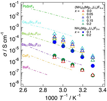
Figure 17. Temperature dependence of the electrical conductivities of NH4(Mg1−x Lix )F3−x (x = 0.1, 0.2) and (NH4)2(Mg1−x Lix )F4−x (x = 0, 0.05, 0.1, 0.15, 0.2) [78]. Electrical conductivities of typical fluoride-ion conductors are also plotted for comparison [52, 65, 70, 79]. Reproduced from [78]. CC BY 4.0.
Download figure:
Standard image High-resolution image3.2.1.6. CsPb0.9K0.1F2.9.
CsPb0.9K0.1F2.9 (PK10), which has a simple perovskite structure, shows a rare combination of high ionic conductivity and excellent electrochemical stability [80]. Its room-temperature conductivity reaches 1.23 × 10⁻³ S cm−1, comparable to the most conductive system, PbSnF4 [81]. Furthermore, its electrochemical stability window is as large as 1.8 V, greatly surpassing those of other highly conductive systems. With these appealing characteristics simultaneously achieved in the solid electrolyte, a cell with higher voltages than other room-temperature-operable solid-state FIBs has been constructed (figure 18).

Figure 18. Comparison of PK10 and MSnF4 (M = Pb, Ba) [80–82]. PK10 possesses a room-temperature ionic conductivity close to the highest value for MSnF4, and its electrochemical stability window (ESW) is much wider, allowing for higher cell voltages. [80] John Wiley & Sons. [Copyright © 2021 WILEY‐VCH Verlag GmbH & Co. KGaA, Weinheim].
Download figure:
Standard image High-resolution image3.2.1.7. KSn2F5.
The ionic conductivity of the layered material KSn2F5 with fluorine in the interlayer is high, even exceeding that of PbSnF4 at high temperatures [83]. KSn2F5 undergoes a structural phase transition at 170 °C from the P3 to P3m1 space group (figure 19). The higher electron densities between Sn and F(1) suggest stronger covalent bonding than between Sn–F(2) or Sn–F(3) (figure 20). A 2D conduction plane is formed at z = 0.32 and 0.68, where nine disordered F− sites are located around Sn2+ at distances from 2.00 to 2.47 Å. The contour plot clearly shows that the bridging and triply bridging fluoride ions make the main contribution to the high ionic conductivity.

Figure 19. Crystal structure of KSn2F5 at (a) 350 and (b) 450 K. The in-plane and the out-of-plane views are shown in the top and bottom panels, respectively [83]. Reprinted from [83], Copyright (2004), with permission from Elsevier.
Download figure:
Standard image High-resolution image
Figure 20. Maximum entropy method analysis of KSn2F5 at 450 K. (a) 3D and (b) 2D views. The isosurface is 1.4 e Å−3 [83]. Reprinted from [83], Copyright (2004), with permission from Elsevier.
Download figure:
Standard image High-resolution image3.2.1.8. Pb5Ga3F19.
The crystal structure of Pb5Ga3F19, which contains interstitial fluorine, is shown in figure 21 [84]. In Pb5Ga3F19, a mutual chemical exchange occurs above 30 °C between all the fluorine sites in the isolated Ga(1)F6 3− octahedra. At higher temperatures, a chemical exchange between these ions and some of the free fluoride ions is observed. Up to 186 °C, the fluoride sites belonging to the Ga(2)F6 3− octahedra chains are not involved in the dynamic process, resulting in the absence of anionic conduction [85].

Figure 21. Crystal structures of Pb5Ga3F19 for (a) model 1 and (b) model 2 with the 14cm symmetry [84]. In models 1 and 2, seven and eight F non equivalent crystallographic sites exist. Both models are consistent with the experimental results. Reprinted with permission from [84]. Copyright (2008) American Chemical Society.
Download figure:
Standard image High-resolution image3.2.2. Single crystals.
Single crystals are suitable for studying the intrinsic ionic conductivity of the bulk because the effect of grain boundaries is small [86–94]. In addition, polycrystalline materials average out the anisotropy of ionic conduction, whereas single crystals provide an insight into the anisotropy. However, the small size of single crystals generally makes them unsuitable for practical applications.
3.2.2.1. KxBi1−xF3−x.
Figure 22 shows the ionic conductivity of the K0.06Bi0.94F2.88 single crystal along with the data for polycrystalline samples with other compositions [95]. The single crystal exhibited the highest ionic conductivity. In a series of K-substituted polycrystalline samples, the conductivity of K0.08Bi0.92F2.84 was the highest, and if a single crystal of this compound could be grown, it would be expected to show a further increase in conductivity. Figure 23 shows the Arrhenius plot of typical ionic conductors: Na-β-alumina is an excellent cationic conductor, and Ca0.15Zr0.85O1.85 is an oxide-ion conductor. The high-temperature conductivity of the K0.06Bi0.94F2.88 single crystal exceeded that of PbSnF4.
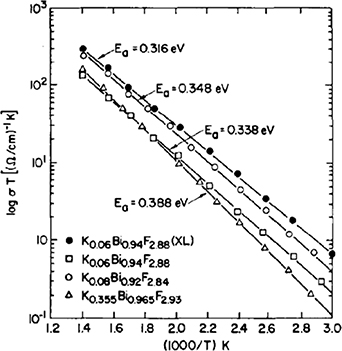
Figure 22. Fluoride-ion conductivity of Kx Bi1−x F3−x (x = 0.06, 0.08, 0.355). The estimated activation energy (Ea) is also shown [95]. Reprinted from [95], Copyright (1981), with permission from Elsevier.
Download figure:
Standard image High-resolution image
Figure 23. Arrhenius plots of several ionic conductors [95]. Reprinted from [95], Copyright (1981), with permission from Elsevier.
Download figure:
Standard image High-resolution image3.2.2.2. Fluorinated h-BN.
Hexagonal boron nitride (h-BN) is classified as an insulator with a band gap of about 5 eV [96]. Solid electrolytes require both electron insulation and ionic conductivity; therefore, selecting an insulator as the base material for fluorination is an intuitive strategy. The in-plane fluoride-ion conductivity of fluorinated boron nitride (F-BN) single crystals is shown in figure 24 [97], and it can be seen that the values for PbSnF4 have been renewed after 43 years, showing high values. F-BN had a huge value of 200 mS cm−1 at room temperature, indicating that the fluoride-ion conductivity of F-BN is not simple thermal activated conductivity. A plateau peculiar to superionic conductors is observed in the temperature dependence of the ionic conductivity at high temperatures. The cause of this plateau was examined by evaluating the composition of fluorine in polycrystalline materials precisely, and the plateau was proposed to corresponded to a structural phase transition.
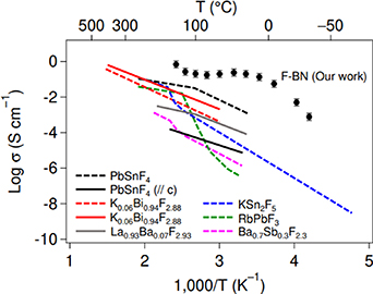
Figure 24. Fluoride-ion conductivity of F-BN and other representative fluorides. The data for the polycrystalline samples and single crystals are shown for comparison [97]. Reprinted from [97], Copyright (2021), with permission from Elsevier.
Download figure:
Standard image High-resolution imageBecause the kinetic energy gain due to the migration of fluoride ions increases with temperature, highly ionic conducting phases tend to be stabilized at high temperatures (figure 25). However, in F-BN, the interlayer distance decreases with decreasing temperature, and the electrostatic repulsion among fluorine in the layers increases. To avoid energy loss due to electrostatic repulsion in the low-temperature phase, it is expected that the covalent bonds are broken and the kinetic energy gain from the transfer between F2 sites instead lowers the overall energy of the system. The competition among the energy gain due to covalent bonding between N−F, the energy loss due to electrostatic repulsion between F−F, and the kinetic energy gain due to fluorine transfer is thought to cause the structural phase transition.

Figure 25. Crystal structures of hexagonal F-BN at (a) low temperature and (b) high temperature. Fluoride ions at the F2 site diffuse in the 2D void [97]. Reprinted from [97], Copyright (2021), with permission from Elsevier.
Download figure:
Standard image High-resolution image3.2.3. Composite materials.
Composite materials have also been studied as fluoride-ion conductors [89, 98]. For example, when LiI is mixed with the insulator, Al2O3, the electrical conductivity is increased by a factor of about 50 [99]. This increase is explained by the formation of highly conductive ionic conduction pathways due to the increased concentration of lithium ions in the space-charge layer formed on the surface of the alumina particles. In particular, the surface effect of Al2O3 is a main factor in the layer formation.
Composites of LiF and fluoride-ion conductors (RF3, CaF2; R: rare-earth element) are frequently formed. The conductivity of the LiF–RF3 composites is usually lower than that of the corresponding RF3 single crystal [100]. A large increase in conductivity only occurs in the LiF–LiGdF4 composite; the large increase in conductivity in the LiF–SmF3 composite is caused by the orthorhombic to tysonite phase transition of SmF3.
The fluoride-ion conducting composite LiF–CaF2 was synthesized by the arc-melting technique and characterized by x-ray and complex impedance analysis [101]. A conductivity increase of approximately three orders of magnitude was obtained owing to the dispersion of LiF in the CaF2 matrix. The increase in conductivity was explained by the space charge model for ionic conduction.
3.2.4. Thin films.
Thin film samples are often used to explore the interface conditions with an electrode (cathode or anode) rather than to evaluate the ionic conductivity of the material itself alone [102–109]. For all-solid-state FIBs, the fluoride-ion conductivity of fluoride-ion conductors is low and the transport mechanism between the electrolyte and the electrode remains unclear.
An effective thin film was designed to examine the rate-determining process at the interface between solid electrolytes and metal electrodes [110]. Tetragonal β-Pb0.78Sn1.22F4 with a high fluoride-ion conductivity was prepared as a thin-film model by pulsed laser deposition. The overall rate constant of the interfacial reaction was determined by chronoamperometric measurements and the extended Allen–Hickling equation that involves mass transfer. The kinetic parameters were well correlated with the fluoride-ion conductivity, which indicates that the mass transfer rather than the charge transfer is the rate-determining factor at the electrode/electrolyte interface. The results for other typical electrolytes, such as LaF3, CeF3, and Li7La3Zr2O12, showed similar behavior. These findings clarified the interfacial reaction kinetics in all-solid-state FIBs and suggested that increasing fluoride-ion conductivity is a crucial strategy for developing all-solid-state FIBs with good rate capabilities.
3.2.5. Nanocrystals.
In nanocrystals, unlike bulk crystals, the particle size has an important effect on the chemical and physical properties [67, 70, 79, 111–114]. Nanocrystalline samples of La1−x Bax F3−x (0 ⩽ x ⩽ 0.2) were prepared by high-energy ball milling of LaF3 and BaF2. The fluoride-ion conductivity significantly increased with the Ba content and reached approximately 10−6 S cm−1 at 330 K, which is an increase of four orders of magnitude compared with nanocrystalline LaF3.
3.2.6. Glasses.
Glasses do not have the long-range ordering of crystals and have many structural defects. These defects are advantageous for ion diffusion, and thus are of interest for ionic conductors. Because isotropic ion diffusion is expected in glasses, they are suitable as ionic conductors from a practical perspective [106, 108, 115–119].
Research on glasses has concentrated on mixed fluorides with the tysonite structure. The glass formation region and the electrical conductivities of the PbF2–MnF2–Pb(PO3)2 system have been reported [120]. A glass with the composition 45PbF2–45MnF2–10Pb(PO3)2 showed a maximum anion conductivity of 4 × 10⁻⁴ S cm−1 at 200 °C (figure 26). The composition variation of the maximum conductivity for these glasses is explained by the displacement mechanism between Mn2+ and Pb2+, which in turn promotes fluoride-ion diffusion.

Figure 26. Fluoride-ion conductivity of PbF2–MnF2–Pb(PO3)2 composites. Inset shows anticorrelation relationship between the activation energy and the pre-exponent [120]. Reprinted from [120], Copyright (1987), with permission from Elsevier.
Download figure:
Standard image High-resolution image3.2.7. Polymers.
Polymer electrolytes have a low ionic conductivity at room temperature, although it tends to increase near the glass transition temperature. In addition, the small ionic transference number of these electrolytes is a drawback. The polyether-based host polymer provides a fluoride-ion conductive polymer electrolyte. Proton, cation, and anion conductors have been reported, but there are few studies of fluoride-ion-conducting polymers. For example, the polymer electrolyte based on the fully aromatic polymer, polysulfone, exhibited a fluoride ion conductivity of 3–5 m S cm−1 at 25 °C [121]. Solid polymer electrolyte systems consisting of a polyethylene oxide-based fluoride-conducting solid polymer, a metal fluoride salt, and an anion acceptor exhibited a fluoride-ion conductivity of 1 × 10⁻⁶ S cm−1 at 303 K [122]. These solid electrolytes have the advantages of flexibility compared with ceramic materials. Table 3 summarizes the structural type, fluoride-ion conductivity, and measured temperature for typical fluoride-ion conductors.
Table 3. Typical fluoride-ion conductors. Structural type, fluoride-ion conductivity, and measured temperature are shown.
| Materials | Structural type | σ (S cm–1) | Temperature (K) | References |
|---|---|---|---|---|
| PbSnF4 | Fluorite | ≈10−3 | 300 | [48] |
| Ba0.7Sb0.3F2.3 | Fluorite | 4.41 × 10⁻⁴ | 433 | [79] |
| PbF2 | Fluorite | ≈10−8 | 300 | [49] |
| CaF2 | Fluorite | ≈10−7 | 625 | [123] |
| Ce3NF6 | Fluorite | 5.0 × 10⁻⁷ | 450 | [61] |
| K0.06Bi0.94F2.88 | Tysonite | 4.0 × 10⁻⁵ | 293 | [95] |
| LaF3 | Tysonite | 10−6 | 300 | [124] |
| La0.9Ba0.1F2.9 | Tysonite | 4.0 × 10⁻⁷ | 300 | [64] |
| RbPbF3 | Perovskite | 0.03 | 500 | [125] |
| CsPb0.9K0.1F2.9 | Perovskite | 1.23 × 10⁻³ | 300 | [80] |
| (NH4)2(Mg,Li)F4−x | Perovskite | 4.8 × 10⁻⁵ | 323 | [78] |
| KSn2F5 | Layered | 5.0 × 10⁻⁶ | 293 | [83] |
| Fluorinated-BN | Layered | 0.2 | 300 | [97] |
| PbF2–MnF2–Pb(PO3)2 | Glass | 4 × 10⁻⁴ | 473 | [120] |
| Polysulfone | Polymer | 3–5 × 10⁻³ | 298 | [121] |
4. Mechanism of ionic conduction
4.1. Determination of dominant factors
The carrier mass and the mobility of electron systems can be evaluated by Hall effect measurements, which are based on the electromotive force that appears in the direction orthogonal to the current and the magnetic field when a magnetic field is applied perpendicular to the current. However, the response of ions to a magnetic field is small compared with that of electrons. The application of a magnetic field causes a field gradient force, a paramagnetic gradient force, electrokinetic force, the Lorentz force, and the magnetic damping force. In a uniform magnetic field, the field gradient force disappears and the paramagnetic gradient force, Lorentz force, and electrokinetic force become important [126]. As shown in figure 27, the Lorentz force occurs in principle, but its effect is tiny in practice. Therefore, it is difficult to evaluate the amount and mobility of ion carriers quantitatively by physical methods (figure 28). It is necessary to organize them like the relationship between physical properties and the carrier concentration for electronic systems [127].
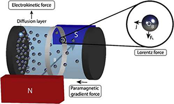
Figure 27. Under magnetic fields, ions experience the electrokinetic force, the Lorentz force, and the paramagnetic gradient force [126]. Reprinted from [126], Copyright (2021), with permission from Elsevier.
Download figure:
Standard image High-resolution image
Figure 28. Transport properties of (a) resistivity (=1/conductivity), (b) thermoelectric power, (c) thermal conductivity, and (d) figure of merit calculated for an idealized semiconductor at room temperature, plotted as a function of carrier concentration. For this example, the optimum thermoelectric performance is attained at a carrier concentration, n, of approximately 1019 cm−3 [127]. Reprinted from [127], with the permission of AIP Publishing.
Download figure:
Standard image High-resolution imageThe AC conductivity measurements of Ba1−x Snx F2 in the cubic and annealed phase were performed [128] to estimate the n value. This was done by fitting the curve to the plateau part of the dispersion curve (figure 29). The total conductivity under dynamic excitation can be written as


Figure 29. Conductivity spectra at different temperatures for the (a) cubic and (b) annealed BaSnF4 [119]. The solid curves are the fitting results using equation (6). Reprinted from [128], with the permission of AIP Publishing.
Download figure:
Standard image High-resolution imagewhere σ(ω) is the AC conductivity, σ(0) is the DC conductivity, A is the temperature-dependent parameter, ω is the excitation frequency, and n is a constant typically between 0 and 1 [129]. This equation was based on literature, in which the universal power law is related to ion hopping in materials [130]. With respect to the part of the conductivity related to the excitation frequency, it is plausible that the same ions that contribute to the DC conductivity could also participate in AC conductivity. Therefore, the A parameter was proposed to be proportional to K and ωp as [131]

From equations (6) and (7), we find
Once ωp is known, the carrier concentration can be determined by substituting ωp into equation (7).
In general, ionic conduction is often discussed in terms of diffusion coefficient D rather than the mobility. D in battery materials is usually estimated by electrochemical measurements. However, the results are highly dependent on the measurement systems. The values of D determined by the electrochemical technique vary by several orders of magnitude for the same material, mainly because of the unknown reaction area of the electrode in the liquid electrolyte. Other methods for measuring D are summarized in figure 30 [132]. Microscopic methods that give D are nuclear magnetic resonance (NMR) spectroscopy, neutron quasi-elastic neutron scattering (QENS), Mössbauer spectroscopy, and muon spin relaxation. NMR is not suitable for D measurements in materials containing magnetic elements such as transition metals, because the change in the spin-lattice relaxation rate (1/T1) cannot be accurately measured due to the effect of spin relaxation by d electrons. In solid electrolytes, this restriction does not apply because they do not contain transition metal elements that are responsible for the redox reaction. The lower limit of the QENS measurement is higher than D at room temperature (below 10−10 cm2 s−1) that is expected for many battery materials, so this method would provide no information near room temperature. Mössbauer spectroscopy is limited to materials containing transition metal elements such as Fe. In contrast, muon spin relaxation implants 100% of the spin-polarized muons into a material, and thus separates the electron and nuclear magnetic fields. The measurement region is also suited to battery materials. μ+ diffuses more easily than fluoride ions in many materials because the mass of μ+ is approximately 1/171 of a fluoride ion.

Figure 30. Macroscopic/microscopic techniques for estimating diffusion coefficient D and motional correlation time τc [132]. QENS: quasi-elastic neutron scattering. Reproduced with permission from [132].
Download figure:
Standard image High-resolution imageWith regard to the effective mass of charge carriers in ionic conductors, some interesting examples have been reported [133]. The electronic states were calculated by applying band calculations to the ionic crystals, such as LiCl, LiF, LiBr, and LiI. Starting from the Schrödinger equation, the effective mass and Bose condensation temperature were evaluated,
Here, ħ is the Planck constant, E(100) is the overlap integral, and as is the lattice constant of the compressed crystal.
Figure 31 shows the Bose condensation temperature as a function of crystal strain. At low temperatures, the possible ionic superconductivity was predicted. However, compared with the μK range for electron systems, low-temperature impedance measurement techniques for ion systems have not yet been established. To the best of our knowledge, measurement systems down to 80 K are only now being commercially available. It is expected that obtaining low-temperature measurements in the high-frequency region above 10 kHz will be difficult due to the structural limitations of the cryostat. The development of a low-temperature measurement technique at least down to 2 K that overcomes this problem is required. Bose condensation, that is, ionic superconductivity, can be observed at realistic temperatures when about 20% strain is applied in LiI.

Figure 31. Bose condensation temperature as a function of as/a for LiF, LiCl, LiBr, and LiI [133]. Dashed line corresponds to Tb = 300 K. Reproduced with permission from [133].
Download figure:
Standard image High-resolution imageSuperconductivity has been reported in heavy-fermion systems, a group of materials in which the effective mass of the electrons is several hundred to a thousand times the mass of free electrons [134]. This high effective mass is similar to that of an ion, suggesting that the mass may not prevent conduction. In addition, according to string theory, both electrons and nuclei are believed to be made from strings. These commonalities suggest that superconductivity could be possible in ionic systems as well.
4.2. Theoretical challenges for battery material exploration
Due to the complexity of battery materials and operation, statistical, machine learning, and data-driven high-throughput approaches may be particularly effective in addressing the challenges in developing FIBs (figure 32). High-throughput screening predicted high theoretical energy densities in fluorides [135]. Energy densities were estimated for 1683 cathode–anode combinations based on thermodynamic data [135], and densities ≳4000 Wh l−1 were predicted for some FIBs. The experimentally measured capacities [136] are smaller than the theoretical values, indicating that the fluoride shuttle reaction does not proceed to completion. The microscopic origin of this discrepancy is not yet clear, and first principles calculations will be instrumental in analyzing the thermodynamics and kinetics of the reaction in various compounds.

Figure 32. Machine learning (ML), data-driven, and high-throughput approaches that can be applied to fluoride-ion conductors (FICs) to help the design of room-temperature FIBs.
Download figure:
Standard image High-resolution imageCombinatorial screening [137] will address other major current limitations of fluoride-ion conductors, including their low ionic conductivity. Obtaining ionic conductivity from first-principles calculations requires a computationally expensive evaluation of the diffusion barrier, hindering high-throughput approaches. Data-driven approaches have only recently begun to be used in FIB materials. Empirical bond valence rules [138] have been used to predict transport channels and activation energies in >29 000 inorganic compounds, including fluorides [139]. Nudged elastic band (NEB) density functional theory calculations were supplemented by empirical methods in a decoupled, dynamic, and iterative (DDI) search [140] for high-fluoride-mobility materials. The search among 9747 fluorides in the Materials Project database resulted in ∼10 stable inexpensive systems with low activation barriers for fluoride diffusion. Beyond simple compounds, the thermodynamics of fluorination/defluorination have been analyzed in 6525 ternary fluorides [141], yielding 807 fluorinated/defluorinated pairs. Among these pairs, 168 pairs had direct reactions, that is, they did not undergo decomposition into more stable intermediates, and could serve as candidates for anode/cathode materials in FIBs. These studies have begun the computational exploration of composition space for the best fluoride ion conductors. Many promising candidates remain unexplored; for example, nonstoichiometric compounds, in which ionic conductivity is known experimentally to increase by orders of magnitude [142]. First-principles and machine learning approaches will be instrumental in finding the best materials for room-temperature FIBs.
There are three major challenges in high-throughput material exploration. The first is the establishment of structural descriptors in the search for ionic conductors. The second is the computational cost of ionic conductivity. The third is the search for materials not found in the database.
If a material is well understood, reasonable descriptors can be set based on physicochemical knowledge of the material. For sulfides, searches focused on the low-barrier ionic pathway between nearly energy-equivalent sites to find superionic conductors [143]. Lithium-ion conducting oxides have been explored by virtual screening with a structural descriptor of a corner-sharing framework in oxides (figure 33), and were validated further by using first-principles molecular dynamics (MD) [144]. The proposed material, LiGa(SeO3)2, showed a high conductivity of 0.11 m S cm−1 at room temperature. When experimental and theoretical data are available, the descriptors can be constructed automatically by machine learning [145–147]. However, it is difficult to find effective descriptors for materials for which sufficient experimental data is not available, such as fluoride-ion conductors.

Figure 33. Crystal structures of known superionic conductors with corner-sharing (CS) frameworks. Structures of known CS superionic conductors (a) Li1+x Alx Ti2−x (PO4)3, (b) LiTa2PO8, and (c) Li1+x Ta1−x Zrx SiO5. The (d) face-sharing, (e) edge-sharing, (f) CS, and (g) isolated connectivity of the framework are shown [144]. Reproduced from [144], with permission from Springer Nature.
Download figure:
Standard image High-resolution imageThe ion diffusion barrier is a fundamental property in the search for high-performance ionic conducting materials and can be calculated by the temperature dependence of the diffusion coefficient obtained using MD simulations or by the NEB method [148]. In both cases, first-principles calculations based on quantum mechanics are used for accurate calculations, which are usually computationally demanding. Several methods have been proposed to reduce the computational cost of ionic conductivity calculations. Among them, machine learning potentials (MLPs), which are constructed using first-principles calculations as the training data, have high computational efficiency and accuracy comparable to that of first-principles calculations [149–151]. Figure 34 shows the diffusion coefficient results calculated using a MLP for Li10GeP2S12, which has a high lithium-ion conductivity [152]. A room temperature diffusion coefficient of 4.9 × 10⁻⁴ cm2 s−1 and a diffusion barrier of Ea = 22 kJ mol−1 were obtained. Converting the diffusion coefficient to lithium ion conductivity using the Nernst–Einstein relation yielded a conductivity of σ = 12 m S cm−1, which agreed well with the experimental value. These results were obtained because MLP allows sufficient statistics to evaluate the diffusion coefficient at low temperatures, which is difficult with first-principles MD due to the large computational load.

Figure 34. Arrhenius plot of lithium-ion self-diffusion coefficients DLi for Li10GeP2S12. The lower inset shows the Arrhenius plot of the coefficients in the c direction, DLi || , and in the ab plane, DLi ⊥. The upper inset shows the ratio of DLi || to DLi ⊥ [152]. Reprinted from [152], Copyright (2021), with permission from Elsevier.
Download figure:
Standard image High-resolution imageAlong with the statistical method using MD, the NEB method is a standard way of calculating Ea. The NEB method finds the diffusion path by moving Li and searching for the energy saddle point, although it is not suitable for automated screening because it requires many first-principles calculations and prior knowledge of the diffusion path. In contrast, the DDI method has been proposed [140], in which a database of diffusion barriers on diffusion pathways is created, and the accuracy of diffusion barriers is improved for new diffusion pathways using approximate equations and NEB as needed. The DDI method has been used to explore fluoride-ion conductors. Algorithms to determine 3D diffusion paths and barriers using effective potentials for the diffusing ions have also been proposed [153]. The effective potentials for lithium ions are generated on a 3D grid based on electrostatic potentials calculated by first-principles calculations. The trial energy is then applied to find 1D to 3D diffusion pathways and diffusion barriers by percolation using the corrugation descriptor. Figure 35 plots the diffusion barriers evaluated by the corrugation descriptor against those calculated by the NEB method for olivine oxides. The results show that the diffusion barrier obtained by the corrugation descriptor has a good correlation with the NEB method. Using the corrugation descriptor, KLi6TaO6 and other materials were proposed based on the results of screening the inorganic crystal structure database, and were experimentally confirmed to be good lithium-ion conductors [154].

Figure 35. Performance of the 3D-corrugation descriptor for a set of olivines. Left: 1D corrugation pathway (in cyan) in LiInSiO4. Black spheres indicate equilibrium Li sites. Right: performance of the 3D-corrugation descriptor in predicting NEB barrier energies for a set of olivines, compared with the bond valence sum (BV) descriptor. Pearson correlation coefficient values (r) are also shown [153]. Reproduced from [153]. CC BY 4.0.
Download figure:
Standard image High-resolution image
Searching for new materials by elemental substitution without changing the crystal structure is an effective method, but there is a limit to the scope of the chemical search space. Methods such as genetic algorithms have been proposed to broaden the scope of searches [155]. Computational high-throughput materials exploration is expected to grow. The method is not limited to the search for lithium-ion conductors and oxide-ion conductors, and it can also be applied to the search for materials including fluoride-ion conductors and sodium-ion conductors. However, it is difficult to screen a wide area of chemical space for material systems with little experimental data and physicochemical knowledge. Additionally, although high-throughput diffusion barrier calculations have become possible, it is still challenging to estimate the ion concentration suitable for the conductivity. Although major changes in conductivity caused by defects and doping are often observed experimentally, they are difficult to predict by high-throughput simulations. This is a challenge for future work.
5. Conclusion and outlook
The ultimate question is whether the fluoride-ion conductivity of inorganic compounds can exceed the maximum value of lithium-ion conductivity [156]. We propose three major strategies to stimulate new research approaches. The first is to develop the synthetic method. Because fluoride ions are charge carriers, it is necessary to synthesize materials containing fluorine or mixed-anion compounds complexed with fluorine and other anions. However, the number of such inorganic materials is small, and future development will be via synthetic methods. Solid-phase reaction methods that use binary metal fluorides as starting materials are reaching their limits. In addition to indirect fluorination using fluorination agents, direct fluorination using F2 gas is effective in expanding the range of synthesis. Direct and indirect fluorination under high pressures is also promising methods.
Second, because the amount of carrier, which is a major factor in ionic conductivity, cannot be understood and controlled accurately, design guidelines cannot be established. Therefore, it is necessary to develop an experimental method to evaluate the number of carriers accurately. Although the number of carriers can be evaluated indirectly, as in electronic systems, work on achieving a deep understanding and precise control of the number of carriers has not progressed. In relation to control, fluoride ions are highly ionic and it is challenging to make them coexist with their vacancies to diffuse fluoride ions. Randomization, i.e. high entropy, may be effective to increase the fluoride-ion conductivity by varying mobility under a constant carrier amount, depending on the rare earth/alkaline earth elements of the cations that make up the material, as applied for lithium-ion conductors [157].
Third, the synergy between experimental and theoretical techniques may provide a breakthrough. Materials informatics and digital transformation are effective methods and it will be interesting to see how much data science, which is powerful in interpolating predictions, contributes to predicting new materials. In the field of electronic systems, the strengths of experimental and theoretical methods have reciprocally contributed to the development of this field. For example, for superconductivity, experiments initially took the lead, and then BCS theory was proposed [158]. Later, high-temperature superconductivity was reported in cuprates, which could not be explained by this theory [4]. After the theoretical prediction of superconductivity at even higher temperatures, superconductivity has recently been observed experimentally at room temperature in hydrides [5, 159].
Acknowledgments
We thank N Yasufuku and K Tani for assistance with preparing the paper. T T gratefully acknowledges support by the Izumi Science and Technology Foundation, the Kato Foundation for Promotion of Science, the Research Grants in the Natural Sciences from the Mitsubishi Foundation, and JSPS KAKENHI Grant Number 22H02167. C P acknowledges a Japanese Government (MEXT) scholarship. R A is grateful for the support from the JSPS Grant-in-Aid for Transformative Research Areas (A) (21H05560).
Data availability statement
No new data were created and analyzed in this study.