

Abstract
Van der Waals antiferromagnets (AFMs) provide a two-dimensional (2D) platform for spintronic devices with exceptional properties. However, the electric transport features of the magnetic order of van der Waals AFM influenced by different field directions and amplitudes has not been demonstrated systematically. In this letter, we investigate the magnetic texture of the exfoliated van der Waals FePS3, a uniaxial AFM with perpendicular anisotropy, detected by the spin Hall magnetoresistance (SMR). Magnetic field- and temperature- dependent longitudinal magnetoresistance measurements in three orthogonal directions for the exfoliated FePS3/Pt nanostructures are conducted. The modulations in the SMR signal enable the separation of two contributions to the SMR, one of which corresponds to the negative signature of AFM SMR caused by in-plane field rotations, and the other of which is caused by canted spins in perpendicular AFM order. Our findings offer great guidance for further research and investigation using SMR approach of the magnetic texture in van der Waals AFMs.
Export citation and abstract BibTeX RIS
1. Introduction
Van der Waals magnets ranging from two-dimensional (2D) ferromagnets (FMs), such as CrX3 (X=I, and Br), Cr2Ge2Te6, and Fe3GeTe2 to antiferromagnets (AFMs) such as CrCl3 have attracted extensive attention because of their impressive stable magnetization ( M ) at atomic thickness [1, 2]. Their emergence provides an exciting platform for exploring new physical phenomena in low-dimensional magnetism and engineering next-generation 2D spintronic devices [3–6]. Compared to the FM counterpart, AFM has attracted enormous interest recently in spintronics due to the absence of stray fields and their terahertz resonant frequency [7, 8]. Nevertheless, the zero net M makes the detection of the antiferromagnetic order challenging. Recently, the spin Hall magnetoresistance (SMR) effects has been developed to detect the magnetic order at the interface between a magnetic insulator with M and heavy metal (HM) with strong spin–orbit coupling [9, 10]. Unlike other techniques, the SMR measurements provide access to the local spin structure, making them an effective tool for characterizing the magnetic structure of the antiferromagnetic material. To date, the SMR effect is demonstrated in three-dimensional (3D) AFM-based heterostructures, such as NiO/Pt [11], α-Fe2O3/Pt [12], Cr2O3/Ta [13], TmFeO3/Pt [7], as well as all-metallic PtMn/W [14]. Different from 3D AFM, the 2D van der Waals AFM layers show extraordinary prospects for spintronic devices with reduced dimensionality, high flexibility, and tunability [15, 16]. However, the magnetic order of van der Waals AFM influenced by different field directions and amplitudes has not been systematically demonstrated by electrical methods yet.
In addition, a uniaxial AFM's magnetic order may response in a variety of ways when a magnetic field is applied, as opposed to magnetic anisotropy and exchange interactions. On one hand, a spin-flop transition takes place with a proper application of magnetic field, which causes the Néel vector to be oriented in the direction perpendicular to the magnetic field. On the other hand, a tilt of the spins that make up the two magnetic sublattices in the direction of the field can also happen in an AFM, causing a net M that also affects the SMR response. If the tilt is more than 45° from the spin-flop direction, this contribution will predominate and result in a typically positive amplitude of the SMR; otherwise, a negative SMR will be resulted in. Consequently, when a magnetic field with a large enough magnitude is rotated in the planes normal to the sample surface, the expected behavior for pure FM and AFM ordering differs due to the different orientations of the magnetic order. For example, when the magnetic field is rotated in the plane perpendicular to the current direction, the Néel vector after spin-flop will always align perpendicular to the spin accumulation, which will lead to zero SMR. As a result, if the SMR is not zero, the presence of M in the AFM will be indicated, which cannot result from the spin flop state. In contrast, for pure FM ordering the zero SMR occurs when the magnetic field is rotated within the plane containing the current direction, where a M rotating coherently with the field is always perpendicular to the current-induced spin accumulation. Depending on the field's amplitudes and directions, these mechanisms may present in the AFM devices. Therefore, it is necessary to study the response in all three orientations to get a complete picture of the contributions that the van der Waals AFM angular-dependent magnetoresistance (ADMR) is made up of.
A class of magnetic van der Waals materials called FePS3 is a transition metal phosphorus trichalcogenide MPX3, where M is a transition metal and X is a chalcogenide. These materials have antiferromagnetic ordering that lasts down to the atomically thin limit, which all crystallize with monoclinic space group C
 symmetry [17]. Very interesting, FePS3 is a uniaxial AFM with perpendicular magnetic anisotropy. Moreover, the bandgap of FePS3 is 1.5 eV and behaves as electrically insulating [18]. Based on the above features, exfoliated flakes of van der Waals FePS3/Pt nanostructures are selected as a representative to investigate these magnetoresistance effects. In this letter, we thoroughly performed the field and temperature dependence of the magnetoresistance effects in van der Waals FePS3/Pt nanostructures.
2. Experimental
The FePS3 based devices were fabricated as follows: Firstly, to strengthen the adhesion between the substrate and the ensuing Pt electrode, a 5 nm Ti coating was deposited by magnetron sputtering onto Si substrates covered with thermal oxidation SiO2. A Pt (5 nm) layer was then deposited using magnetron sputtering. In the following stage, the Pt (5 nm)/Ti (5 nm) films were patterned into 10 μm wide and 14 μm long Hall bars by ultraviolet lithography with an Argon ion etching process. Then, the few-layer FePS3 flakes were mechanically exfoliated in a nitrogen atmosphere by adhesive tapes from a bulk crystal of FePS3. The dimension of the FePS3 flakes' surface area reached μm level. The color of the few-layer FePS3 flakes and the atomic force microscope test, which determines the thickness of the few-layer FePS3 flakes, were used to determine the number of tape adhesions. Subsequently, the desired FePS3 flakes with different thickness were located and transferred onto Ti (5 nm)/Pt (5 nm) Hall bar electrodes. During the synthesis of the structure, the film thickness was calibrated by the x-ray reflectivity measurements. The crystallographic structure was characterized by high resolution x-ray diffraction (Bruker D8 Discover). The surface topography of the FePS3 flakes was analyzed by atomic force microscopy (AFM, Asylum). The magnetic properties were characterized by superconducting quantum interference devices (Quantum Design). As part of a four-point measurement system, a constant current of I = 100 μA is applied along the long edge of the Hall bar while simultaneously recording the voltage drop along the wide edge of the Hall bar. The longitudinal resistivity (ρxx) of the devices was characterized while rotating an applied magnetic field in three orthogonal planes using the physical property measurement system (Quantum Design).
3. Results and discussion
Figure 1(a) illustrates the optical image of exfoliated FePS3 flakes and the final device measured in our experiments. The surface morphology of the FePS3/Pt device (inset of figure 1(b)) was measured by AFM, and the yellow (green) dashed lines delineate the edge of the FePS3 (Pt) layer. The height profile shown in figure 1(b) indicates that the thickness of the FePS3 layer is about 16.1 nm, relating to the location of the red dashed line in the inset. Figure 1(c) shows the results of x-ray diffraction spectroscopy (XRD) of experimental FePS3 crystals (red) with corresponding JCPDF pattern (30–0663) (blue), which reveals a pure single-crystal phase with preferred (0 0 1) orientations. Figure 1(d) shows the thickness dependence of Raman spectrum for FePS3 samples obtained with an excitation wavelength of 532 nm and power of 0.5 mW measured at 300 K. Six Raman peaks is resolved in the spectrum, whose values located at 106 cm−1, 162 cm−1, 230 cm−1, 252 cm−1, 285 cm−1, 384 cm−1, respectively. The bulk FePS3 crystal is expected to have 30 irreducible zone-center phonon modes denoted by Γ = 8Ag + 6Au + 7Bg + 9Bu, among which Ag and Bg are Raman active modes [17–19]. The corresponding Raman active modes of the FePS3 samples have been noted in figure 1(d), respectively. Especially, the first peak is attributed to spin-order-induced Raman peaks, in agreement with the previous report of Raman measurements for van der Waals FePS3 [19, 20]. With the decreasing of the thickness of FePS3 flakes, the normalized intensity becomes weaker.

Figure 1. (a) The optical image of the exfoliated FePS3 flakes and the final device measured in our experiments. (b) The height profile is taken along the white dashed lines in the inset: top view of FePS3/Pt measured by atomic force microscopy (AFM). The yellow (green) dashed lines outline the edge of the FePS3 (Pt) layer. (c) XRD diffraction pattern of FePS3 crystals (red) with corresponding JCPDF pattern (30‐0663) (bule). (d) Thickness dependence of Raman spectrum measured at 300 K for FePS3 samples.
Download figure:
Standard image High-resolution imageWe subsequently perform ADMR measurements when rotating the magnetic field in different orientated planes for the FePS3/Pt devices. Figures 2(a) and (b) demonstrates the atomic schematic illustration of antiferromagnetic van der Waals FePS3/Pt nanostructures in xy and xz views, respectively. Below the Néel temperature TN = 120 K, the spins of the Fe atoms are antiferromagnetic coupled with their nearest neighbors in each layer of the crystal's xy plane, while the interlayer exchange coupling between the Fe spins are ferromagnetic [19, 20]. Schematic of the ADMR measurements of the rotating angles α, β and γ are defined in figure 2(c), respectively. For α and β sweeps, ρxx ( M||y) is chosen as the reference points for calculating Δρxx, i.e. Δρxx/ρxx = (ρxx(α) ‒ρxx(α = 0°))/ρxx(α = 0°), and Δρxx/ρxx = (ρxx(β) ‒ρxx(β = 90°))/ρxx(β = 90°). For the γ sweep, ρxx ( M||x) is chosen as the reference points for calculating Δρxx, i.e. Δρxx/ρxx = (ρxx(γ) ‒ρxx(γ = 90°))/ρxx(γ = 90°).

Figure 2. Illustration of ADMR measurements for the FePS3 /Pt nanostructures in (a) xy and (b) xz views, respectively. The gray, yellow, gold, and violet spheres represent phosphorus (P), sulfur (S), iron (Fe) atoms, respectively. The arrows show the spin ordering of both crystals in antiferromagnetic state. ρxx is measured along the x-axis, which is parallel to the direction of the electric current flow J e. (c) Definitions of the rotating angles α, β, and γ, rotating in yx, zy, zx planes are defined, respectively.
Download figure:
Standard image High-resolution imageAs the FePS3 is insulating, the effective dimensions of the devices are decided by the dimensions of the Pt Hall pattern, which are with 10 μm width and 14 μm length. We have collected the transport data from two devices with different thickness, as demonstrated in figure 3. Regardless of the difference in FePS3 flake thickness, the field dependency of the Δρxx/ρxx measurements of 4 T at 5 K for the FePS3 flakes/Pt devices displays the same trend in three rotating magnetic field sweeps, even though a slight shift in the peak location. We selected the thinner (16 nm) FePS3 flakes to conduct the following measurements with various field strengths and temperatures in order to further examine the magnetoresistance effects. Figure 4 illustrates field dependency of the Δρxx/ρxx measurements in van der Waals FePS3/Pt nanostructures at 5 K with a constant magnetic field ranging from 1 T to 9 T, respectively. It has been reported that the anisotropic magnetoresistance (AMR) is governed by the angle between the applied current and the M direction αcM , while the SMR depends on the angle between the spin polarization of spin accumulation induced by the current and the M direction ασM [9]. As seen in figure 4, the Δρxx/ρxx in every sweep is a periodic function of the rotating angle with a period of 180°. Regardless of the films' rotational angles, whether they are in-plane or out-of-plane, Δρxx/ρxx is enhanced as H ⩾ 2 T and varies according to the magnetic field intensities.
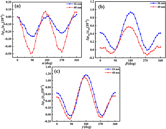
Figure 3. Δρxx/ρxx measurements varying with different thickness of FePS3 flakes at a constant magnetic field of 4 T in (a) α, (b) β, (c) γ sweeps at 5 K for FePS3/Pt nanostructures, respectively.
Download figure:
Standard image High-resolution image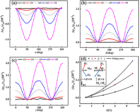
Figure 4. Δρxx/ρxx measurements varying with different magnitudes of measuring magnetic fields from 1 T to 9 T at 5 K in (a) α, (b) β, (c) γ sweeps for van der Waals antiferromagnet FePS3/Pt nanostructures, respectively. (d) Magnetic field dependence of the Δρxx/ρxx measurements with a constant magnetic field of 9 T in three different rotating angles α, β, and γ for van der Waals antiferromagnet FePS3/Pt nanostructures. The solid curve is the fitting with Δρxx/ρxx = aH2 + bH+ c. Inset: The canting local magnetization moment M IP ( H ┴ z ), M a or M a' ( H ||z ) of sublattice A and B into y direction by applied fields.
Download figure:
Standard image High-resolution imageIt has been reported that the SMR in the longitudinal resistance (ρL) of a HM in contact with an AFM with two sublattices A and B reads [11–14]
where ρ0 is approximately equal to the normal resistivity of the metallic Pt layer,  represents the SMR coefficient for the magnetic sublattice X = A, B with
  ⩽ ρ0, and
  denotes the projection of
  on the transverse direction
y
(perpendicular to
j
in the
x-y
plane). Without canting of the sublattice
M
, the direction
on the transverse direction
y
(perpendicular to
j
in the
x-y
plane). Without canting of the sublattice
M
, the direction  and
and  are given by the Néel vector
l =
(
are given by the Néel vector
l =
( –
– )/2 with its projection
l
j and
l
t on
j
and
t
, respectively. For magnetic field larger than the spin-flop field of the AFM,
l
is perpendicular to the external magnetic field, resulting in the negative SMR which exhibits a 90° phase shift with respect to col-linear HM/FM nanostructures [12]. The Δρxx/ρxx oscillations are barely perceptible for
H
⩽ 1 T, as illustrated in figure 4(a), but they become more pronounced for
H
⩾ 2 T and change depending on the magnetic fields intensities. However, the sign of Δρxx/ρxx is always negative, regardless of the strength the magnetic field. The observations are consist with the SMR signature from AFMs [12, 13, 21–24]. Additionally, it has been noted that in conventional AFMs, the SMR amplitudes have a quadratic dependence on field for small magnetic fields range, and then saturate at larger fields, based on the evolution of the antiferromagnetic multi-domain state with the Néel vector of each domain for an applied magnetic field [12]. Instead, in the exfoliated FePS3/Pt nanostructures, a combination of contributions, one with a quadratic increase and one with a linear increase with increasing magnetic field intensity, fits the data in this case more accurately, as shown in figure 4(d). The modulations of the Δρxx/ρxx shows a combination of quadratic and linear trends upon increasing the magnetic field. However, up to an applied magnetic field of 9 T, a saturation for the SMR amplitude has not been achieved, consisting with the previous reports of high saturated magnetic field for FePS3 [25]. As a result, it is reasonable to infer that there are additional signal contributions to the SMR amplitudes in addition to the long-range AFM ordering.
)/2 with its projection
l
j and
l
t on
j
and
t
, respectively. For magnetic field larger than the spin-flop field of the AFM,
l
is perpendicular to the external magnetic field, resulting in the negative SMR which exhibits a 90° phase shift with respect to col-linear HM/FM nanostructures [12]. The Δρxx/ρxx oscillations are barely perceptible for
H
⩽ 1 T, as illustrated in figure 4(a), but they become more pronounced for
H
⩾ 2 T and change depending on the magnetic fields intensities. However, the sign of Δρxx/ρxx is always negative, regardless of the strength the magnetic field. The observations are consist with the SMR signature from AFMs [12, 13, 21–24]. Additionally, it has been noted that in conventional AFMs, the SMR amplitudes have a quadratic dependence on field for small magnetic fields range, and then saturate at larger fields, based on the evolution of the antiferromagnetic multi-domain state with the Néel vector of each domain for an applied magnetic field [12]. Instead, in the exfoliated FePS3/Pt nanostructures, a combination of contributions, one with a quadratic increase and one with a linear increase with increasing magnetic field intensity, fits the data in this case more accurately, as shown in figure 4(d). The modulations of the Δρxx/ρxx shows a combination of quadratic and linear trends upon increasing the magnetic field. However, up to an applied magnetic field of 9 T, a saturation for the SMR amplitude has not been achieved, consisting with the previous reports of high saturated magnetic field for FePS3 [25]. As a result, it is reasonable to infer that there are additional signal contributions to the SMR amplitudes in addition to the long-range AFM ordering.
The schematic response of the magnetic sublattices m A and m B with magnetic fields parallel and perpendicular to the easy axis (z direction) of bulk FePS3 is shown in the inset of figure 4(d). Transverse M ( M IP) is present when the applied magnetic field perpendicular to the easy axis. The applied magnetic field along the easy axis induces an unusual canting of sublattices A and B into the y direction [26, 27]. Given that the canting is brought on by an increase in Zeeman energy, sublattice B must cant more for X = A; as a result, M a > M a'. Therefore, another contribution to the evolution of the SMR in van der Waals FePS3/Pt nanostructures is possible because of the canted local M moment induced by an external magnetic field, while it is mainly the Néel vector that contribute to the SMR resulting in a sole quadratic dependency of SMR amplitude on the magnetic field in conventional AFMs such as NiO and α-Fe2O3 [11, 12, 28].
As mentioned above, the field modulations of SMR exhibit a combination of quadratic and linear trends. Particularly, the ratio of Δρxx/ρxx measured with the magnetic field rotating out of the film plane is significantly higher than that with the rotating angles in the film plane. For conventional FM-based nanostructures, SMR ought to remain constant when M is rotated in the xz plane, since m y and, consequently the reflection of J s, are unchanged [9]. Thus, any resistance variation in this condition can be attributed to AMR. In FM/Pt nanostructures, FM caused by magnetic proximity effects has also been seen, which could make it difficult to employ thin Pt as a detector of pure spin current. However, with compensated AFMs, where a net magnetism may only be observed locally due to uncompensated domain borders, the size of this impact is anticipated to be substantially lower [29]. In this way, it is logical to assume that there are other signal contributions, such as the canted local M moment. On the other hand, AMR should remain constant if M is rotated in the yz plane tracked by angle β, thus any resistance changes when the magnetic field is rotated in yz plane can be attributed to SMR. No matter how strong the magnetic field ( H ⩾ 2 T) is, the sign of Δρxx/ρxx rotated in yz plane is always positive. It agrees with the SMR observed in FM/Pt nanostructures. This demonstrates from a different perspective that a ferromagnetic signal contribution exists and that it may be connected to the canted local M moment. Therefore, in these two cases, the variation in Δρxx/ρxx indicates the origin of two distinct physical processes, which is consistent with the modulations of the in-plane field strength.
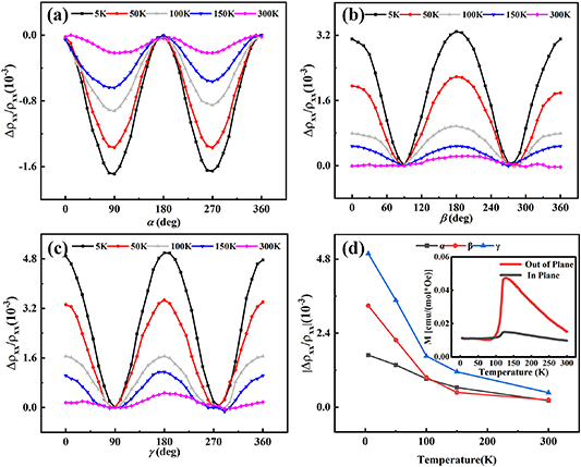
Furthermore, figure 5 depicts the temperature evolution of the Δρxx/ρxx amplitudes at a constant magnetic field of 9 T for the van der Waals FePS3/Pt nanostructures. As can be observed, the modulation of the effect evolves differently with temperatures for measurements in different rotating planes, but the sign of the modulation remains constant across the whole temperature range. When the field rotates in the yz plane, a relatively larger SMR is observed at all temperatures. While the field rotates in the zx plane, however, the modulation is greatest at low temperatures and sharply reduces at higher temperatures. Around 120 K, a steeper slope is observed, which is explained by the ordering of the Néel vectors. A tiny amount of modulation is still discernible in the data above the TN and up to 300 K, but the signal size is now comparable to the noise. The magnetic susceptibilities of bulk FePS3 measured with the in plane and out of plane magnetic fields are sketched in the inset of figure 5(d), respectively. It supports that the easy axis of the FePS3 is perpendicular to the film plane. When the measuring temperature is much lower than the Néel temperatures, the ratio of Δρxx/ρxx measuring with the magnetic field rotating out of the film plane is larger than that of measuring with the rotating angles in the film plane. However, with the increase of the measuring temperatures, the ratio of Δρxx/ρxx gradually approach to the same magnitudes in three mutually orthogonal rotation planes. It is attributed to the variety of the magnetic anisotropy for the van der Waals AFM FePS3 with the increase of the measuring temperatures. Comparison of the MR in three mutually orthogonal rotation planes, a SMR signal with a magnitude (3.3 × 10⁻⁴) several 30 K above the Néel temperature is obviously detected, which is attributed to a field-induced paramagnetic M in FePS3 layers. Hence, the presence of a modulation with both β and γ indicates that both a FM (or para-magnet) component and an AFM component contribute to the SMR.
Figure 5. Δρxx/ρxx measurements varying with various temperatures at a constant magnetic field of 9 T in (a) α, (b) β, (c) γ sweeps for van der Waals antiferromagnet FePS3/Pt nanostructures, respectively. (d) Temperature dependence of the Δρxx/ρxx measurements with a constant magnetic field of 9 T in three different rotating angles α, β, and γ for van der Waals antiferromagnet FePS3/Pt nanostructures. Inset: Temperature dependence of in-plane and out-of-plane susceptibilities of the FePS3 samples.
Download figure:
Standard image High-resolution image
In summary, we have measured the evolution of the ADMR in van der Waals perpendicular AFM FePS3/Pt nanostructures. Two contributions to the SMR are present, one of which corresponds to the negative signature of AFM SMR caused by in-plane field rotations and the other of which is caused by canted spins in perpendicular AFM order. Below the Néel temperature of the exfoliated FePS3 flakes, the SMR exhibits an anisotropic signature. However, above its Néel temperature, the anisotropy characteristic of the SMR signal vanishes. Comparison of the MR in three mutually orthogonal rotation planes, a SMR signal with a magnitude (3.3 × 10⁻⁴) several 30 K above the Néel temperature is obviously detected, which is attributed to a field-induced paramagnetic M in FePS3 layers. Our results provide great guidance for exploring magnetic textures in van der Waals magnets by SMR method and implementing low-dimensional materials in the next-generation spintronic applications.
Acknowledgments
This work is supported by the National Natural Science Foundation of China (No. 6204217), the Fundamental Research Funds for the Central Universities, China university of Geoscience, Wuhan (No. G1323521144), the Project (No. CARCH201911) is supported by the State Key Laboratory of Computer Architecture, ICT, CAS and the Hubei Key Laboratory of Advanced Memories. W N L thanks the support by the Fundamental Research Funds for the Central Universities under Grant No. 20720220035.
Data availability statement
The data generated and/or analysed during the current study are not publicly available for legal/ethical reasons but are available from the corresponding author on reasonable request.