

Abstract
Terahertz sensors are promising for biomedical, environmental and security applications. Challenges in terahertz sensing have been the limited sensitivity and small figure of merit (FOM). Here we propose an ultra-sensitive terahertz sensing platform based on the Rayleigh anomaly (RA) in hyperbolic metamaterial gratings, which are composed of periodic slits patterned in paired metal-dielectric multilayers. Simulation results show that, under normal incidence with transverse-magnetic polarization and designed with proper parameters, the proposed structure has a super-high quality factor of 516, an ultra-high sensitivity of 1.56 THz RIU−1 (or  nm RIU−1), and extremely large FOM of 355 RIU−1 at frequency of 2.272 THz, corresponding to a large normalized sensitivity of 0.69 RIU−1. By comparing with other multilayered gratings, we attribute this exceptionally high sensing performance to the strong local field enhancement over an extremely large area in the sensing region at the RA frequency, which is found to be unique for hyperbolic metamaterial gratings. We further show that the resonance frequency decreases linearly with the grating period, following the RA equation, whereas the large normalized sensitivity keeps constant. We expect this work provides a novel strategy to design extremely sensitive sensors in terahertz as well as other frequency regimes.
Export citation and abstract BibTeX RIS
1. Introduction
Terahertz (THz) wave refers to largely unexplored electromagnetic radiation with a frequency of 0.1– Hz (corresponding to a wavelength of 30 µm–3 mm). Because of the unique properties such as perspective, nonionizing, and spectroscopic fingerprints for many complex molecules, terahertz waves have promised to provide non-contact, non-destructive and label-free sensing in biological, chemical and security applications [1–4]. Compared with the existing sensors in the visible or near-infrared regime, challenges for terahertz sensors have been the limited sensitivity and the small figure of merit (FOM) [1], the latter of which is defined as the ratio of the sensitivity to the linewidth, i.e. the full-with-half-maximum (FWHM) of the resonance in spectra.
In order to address these challenges, great efforts have been put on exploring novel configurations with different physics of terahertz sensors for better performance [5]. Over the years, attenuated total reflection spectroscopy [6], differential terahertz time-domain spectroscopy [7, 8], surface-wave resonance [9], waveguides [10, 11], spoof plasmon surfaces [12–14], antennas [15, 16], metamaterials [17–19], and photonic crystal cavity defect modes [20] have been proposed and developed. Among these configurations, terahertz metamaterials have shown their potentials in sensing applications [18] because these structures significantly improve the sensing performance through great local field enhancement at resonance. To date, most terahertz metamaterial sensors have been realized based on planar split-ring resonators (SRRs) [21–25] or their variations such as double SRRs [26]. However, these planar terahertz metamaterials still suffer from either relatively low sensitivity or low FOM or both [27]. As an example, the sensitivity of a typical SRR-based terahertz sensor is only  's GHz RIU−1.
To further improve the sensitivity, Wang et al [28] proposed and demonstrated superior sensitivity of 788 GHz RIU−1 with vertical SRRs, and Xu et al [29] proposed metamaterial-dielectric-metal structure showing a high sensitivity of 3.5 THz RIU−1. However, the FOMs of these lossy planar metamaterials are still small, thereby demanding for new designs that enable narrower linewidth or higher quality factor. Approaches to tackle this challenge include: (a) to make use of Fano resonances [30–35], of which the maximum reported quality factor can reach 50 [30, 33, 34], the maximum reported sensitivity is 1.9 THz RIU−1 [33], and thus the maximum reported FOM reaches about 6.6 RIU−1 [33]; (b) to make use of lattice resonances in antenna arrays, which leads to a quality factor of Q ≈ 20 but an FOM of 3.8 RIU−1 at  m [36]; (c) to make use of the Rayleigh anomaly (RA) in SRRs, of which the quality factor can reach 104, but the sensitivity is only 0.11 THz RIU−1, corresponding to FOM of 922 [37]; (d) to adopt bound states in the continuum in metasurfaces, of which the quality factor can reach 1016 [38], but the sensitivity is only 0.78 THz RIU−1, corresponding to FOM of 284. In other words, these approaches, suffer from either limited sensitivities or limited FOMs.
In this work, we propose a novel THz sensing configuration with ultra-high sensitivity and meanwhile extremely large FOM based on the RA in hyperbolic metamaterial gratings. The grating is composed of periodic slits patterned in at least two pairs of metal-dielectric multilayers and is illuminated under normal incidence with transverse-magnetic (TM) polarization. Strikingly, we will show that the proposed structure has a high quality factor of 516 at the resonance frequency of 2.272 THz (or the resonance wavelength of 132 µm), an extremely high sensitivity of 1.56 THz RIU−1, and meanwhile an ultra-high FOM value of 355 RIU−1. In order to understand the exceptionally high sensing performance, we will unveil the underlying physics by comparing the hyperbolic metamaterial gratings with other multilayered gratings. By discussing the effects of the grating size, we will also show that the resonance frequency and the sensitivity can be scaled linearly with the grating period, following the RA equation.
2. Results and discussion
2.1. Design and simulation setup
Figure 1 illustrates the proposed THz sensing configuration based on hyperbolic metamaterial grating of width w and period Λ. The hyperbolic metamaterial is composed of four pairs of metal gold and insulator polyimide (PI) multilayers (denoted as 'MIMIMIMI'), of which the heights are  m and
m and  m, respectively. The grating sits on a high-resistivity silicon substrate which is transparent in the terahertz regime, and is immersed in liquid.
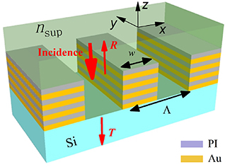
Figure 1. Schematic of the proposed hyperbolic metamaterial grating for THz sensing. The hyperbolic metamaterial is composed of four pairs of metal–insulator multilayers. The grating has width w and period Λ.
Download figure:
Standard image High-resolution imageThe proposed hyperbolic metamaterial grating can be fabricated using state-of-the-art micro-fabrication techniques. The gold film is first deposited on the high-resistivity silicon substrate, followed by the spin-coating of the PI film. By repeating these procedures four times, we can obtain the four pairs of gold-PI multilayers. The periodic slits in the as-deposited multilayers can be fabricated by means of femtosecond laser writing.
All the calculations were performed with a home-built package for rigorous coupled wave analysis method, which is developed following [39, 40], and which is shown to be efficient for calculating the reflectance and transmittance spectra, R and T of periodic structures. The absorbance spectra A is then obtained through  . In the simulations, we adopted 301 retained orders, which are large enough to reach the convergence regime. The relative permittivity of the high-resistivity silicon substrate is set to be
  , the refractive index of the PI is set to be
  , and the relative permittivity of gold is modeled using the Drude model with the plasma frequency
  rad s−1 and the damping coefficient
  s−1 [41]. Unless otherwise specified, the terahertz plane wave has TM polarization (polarized along x direction) and unitary amplitude (
 ), and normally impinges onto the hyperbolic metamaterial from the liquid superstrate side, and the grating has ridge width
  m and period
  m, and is immersed in liquid with refractive index of
  . As references, the same-sized gratings in other multilayered films, including a single layer metal film (denoted as 'M'), a bi-layered metal-dielectric film ('MI'), a metal–insulator–metal film ('MIM'), and similarly 'MIMI', 'MIMIM', 'MIMIMI' and 'MIMIMIM' films will also be investigated.
2.2. Reflectance, transmittance and absorbance spectra
Figure 2 shows the reflectance, transmittance and absorbance spectra for various multilayered gratings. Figure 2(a) shows that for the M grating, both the reflectance and transmittance spectra exhibit abrupt changes around the (1,0) order RA frequency, which is expressed as

and which is calculated to be  THz for
  m with c the speed of light in vacuum. The absorbance spectrum is negligible, indicating little absorption loss due to the metal absorption. For the MI grating, figure 2(b) shows that there exists a small peak locating at
  in the absorbance spectrum. This absorbance peak becomes pronounced for the MIM grating, and meanwhile a narrow and shallow Fano-type dip appears at
  within the broad resonance peak of the reflectance spectrum, as shown by figure 2(c). For the MIMI grating, the absorbance peak and the reflectance dip, both of which locate at
  , become sharp with large modulation depths and narrow linewidths, as shown by figure 2(d).
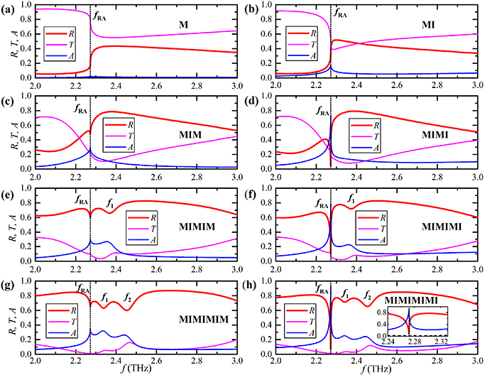
Figure 2. Calculated reflectance, transmittance and absorbance spectra for various multilayered gratings: (a) metal ('M'), (b) metal–insulator ('MI'), (c) metal–insulator–metal ('MIM'), (d) 'MIMI', (e) 'MIMIM', (f) 'MIMIMI', (g) 'MIMIMIM', (h) 'MIMIMIMI'.  is the RA frequency, as indicated by the vertical dotted lines, and f1 and f2 are the other two resonance frequencies.
Download figure:
Standard image High-resolution imageHowever, by adding a metal grating on top, i.e. for the MIMIM grating, the absorbance peak and reflectance dip locating at  are greatly suppressed, whereas a new resonance with broad linewidth appears around
  THz, as shown by figure 2(e). By further adding an insulator grating, i.e. for the MIMIMI grating, figure 2(f) shows that the resonance at
  becomes sharp again, whereas the resonance at f1 is almost unchanged. Similar behaviors can be found by further adding more metal and insulator gratings on top in sequence. For example, figure 2(g) shows that for the MIMIMIM grating the resonance at
  is suppressed again, and meanwhile another resonance locating at f2 appears; figure 2(h) shows that for the MIMIMIMI grating the resonance at
  becomes sharp again, whereas the resonances at f1 and f2 remain unchanged and broad.
Therefore, we discover that for the resonances at  , the absorbance peak and reflectance dip become sharp only for at least two pairs of MI films. The more pairs of the MI films, the larger modulation depth for the resonance at
  , and the more high-order resonances with broad linewidths. Strikingly, figure 2(h) shows that, for the MIMIMIMI grating, the Fano-shaped reflectance dip locating at
  has an extremely narrow asymmetric linewidth, i.e. FWHM of
  GHz. This corresponds to an exceptionally high quality factor of
  .
.
However, by removing the top insulator grating from the grating in at least two pairs of MI films, the Fano-shaped resonance at  is broadened with smaller modulation depth, whereas the high-order resonances (if applicable) are unchanged; by adding a metal grating on top, the resonance at
  is also broadened, and meanwhile another high-order resonance appears.
We emphasize that the above phenomena can be observed only for the TM polarization under normal incidence. Under oblique incidence or for the TE polarization, although the RA phenomenon also occurs, the FWHM of the resonance is very large (not shown for clarity), corresponding to limited quality factor. This is why we restrict ourselves to TM polarization under normal incidence in this work.
We also note that, replacing gold with silver or aluminum in the multilayered gratings leads to similar results (not shown for clarity). This is because these metals behave similarly in the terahertz regime. Therefore, in fabrications one can replace gold with aluminum, which is cheaper and chemically stable.
2.3. Underlying physics
In order to understand physics underlying the far-field spectral features, we plot the near-fields associated with the resonances at  in figure 3, and with high-order resonances at f1 and f2 in figure 4. From the M grating to the MIMI grating, figures 3(a)–(d) show that the local electric field amplitude
  is gradually enhanced over an increasing area in the liquid region. Correspondingly, the reflectance dip and the absorbance peak at
  in figures 2(a)–(d) become more pronounced and sharper. Remarkably, for the MIMI grating, the electric field amplitude is enhanced by an order of magnitude over an extremely large and long-ear shaped area in the liquid region, as shown by figure 3(d). This greatly enhanced near-field, which is partially confined to the lossy PI layers, can explain the sharp reflectance dip and absorbance peak at
  in figure 2(d).
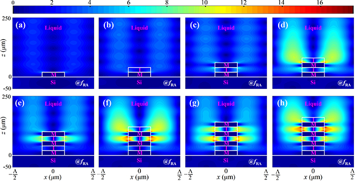
Figure 3. Electric field distributions  for the multilayered gratings at
  THz: (a) M, (b) MI, (c) MIM, (d) MIMI, (e) MIMIM, (f) MIMIMI, (g) MIMIMIM, (h) MIMIMIMI.
Download figure:
Standard image High-resolution image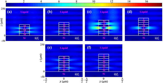
Figure 4. Electric field distributions  for the multilayered gratings at (a)–(d) f1 and (e), (f) f2: (a) MIMIM, (b) MIMIMI, (c) MIMIMIM, (d) MIMIMIMI, (e) MIMIMIM, and (f) MIMIMIMI. Note that f1 and f2 are marked in figures 2(e)–(h).
Download figure:
Standard image High-resolution imageBy adding a metal grating on top, i.e. for the MIMIM grating, figure 3(e) shows that the region of enhanced electric field is reduced from the long-ear-shaped large area to a much smaller area around the top insulator layer. This corresponds to a less sharper resonance at  in figure 2(e). However, by further adding an insulator grating on top, i.e. for the MIMIMI grating, the greatly enhanced electric field changes back to the large and long-eared shape in the liquid, as shown in figure 3(f). Correspondingly, the resonance at
  becomes sharp again in figure 2(f). Similar behaviors in the near-field distributions and far-field spectra can be observed by sequentially adding more metal and insulator gratings on top, as shown by figures 3(g), (h) and 2(g), (h), respectively.
Figures 3(b), (d), (f) and (h) also show that the more pairs of metal-dielectric layers, the larger portion of the electric field is confined to the lossy PI layers. As a result, the absorption peak at  increases with the metal-dielectric layer, as shown by figures 2(b), (d), (f) and (h).
Therefore, we discover that at least two pairs of MI layers with gratings are unique in having a sharp dip (or peak) in the reflectance (or absorbance) spectra at  , and that this unique characteristic originates from the extremely large and long-ear-shaped region of greatly enhanced electric field in the liquid at the RA frequency. Since at least two pairs of MI thin films can be equivalently modeled as hyperbolic metamaterials with effective dielectric tensor parallel (
 ) and perpendicular (
 ) to the x–y plane given by [42]
our results suggest that the sharp reflectance dip and absorbance peak, and the large and long-ear-shaped area of greatly enhanced electric field at the RA frequency are unique characteristics of the hyperbolic metamaterial gratings.
For high-order resonances at f1 and f2 with broad linewidth in figures 2(e)–(h), we find that the corresponding electric field enhancement is very weak or is moderate but over limited area, as shown by figure 4. These results further highlight the strong correlation between the sharp absorbance peak (reflectance dip) and the greatly enhanced near-fields over a large area.
2.4. Terahertz refractive sensing performance
Hereafter, we focus on the MIMIMIMI hyperbolic metamaterial grating. Taking advantage of the exceptionally high quality factors and the associated greatly enhanced near-fields over an extremely large area in the liquid region, we expect that the hyperbolic metamaterial grating can act as an excellent platform for ultra-sensitive terahertz sensing. In order to investigate the changes in the reflectance spectra as the liquid environment is modified, the grating is immersed in various fluids, namely, gasoline ( ), diesel (
 ), and liquid paraffin (
 ).
).
Figure 5(a) shows that, as the refractive index of the liquid nsup increases, the reflectance dip with smaller modulation depth shifts to lower resonance frequency, which locates exactly at the RA frequency determined by equation (1), as indicated by the vertical dotted lines. As a result, the resonance frequency decreases linearly as nsup increases, as shown by figure 5(b). The sensitivity, defined as  , is calculated to be S = 1.56 THz RIU−1, or
  nm RIU−1. In order to compare the sensitivity S of various terahertz sensors operating at different resonance frequencies f0, Hu et al [29] recently proposed the concept of normalized sensitivity, which is defined as

With equation (4), the normalized sensitivity of the proposed MIMIMIMI hyperbolic grating is calculated to be  .
.
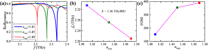
Figure 5. (a) Calculated reflectance spectra for the MIMIMIMI grating immersed in different refractive indices of liquid. (b) Reflectance dip wavelength and (c) FOM versus liquid refractive index. The vertical dotted lines in (a) indicate RA frequencies determined by equation (1).
Download figure:
Standard image High-resolution imageAdditionally, figure 5(a) shows that the linewidth of the reflectance dip  decreases as nsup increases: for
  , 1.45 and 1.49,
  GHz, 4.4 GHz and 4.0 GHz, corresponding to quality factors of Q = 229, 516 and 552, respectively. Therefore, the FOM defined by

are 153, 355 and 390 RIU−1 for  , 1.45 and 1.49, respectively, as shown by figure 5(c).
We summarize the sensing performance of our proposed structure and those of the reported terahertz sensors in table 1. The comparison clearly shows that for different terahertz sensor configurations and even for the same configuration, the operation frequency f0, the quality factor Q, the sensitivity S, the normalized sensitivity  and the FOM are distinct. Among these configurations, we find that the quality factor of the proposed hyperbolic metamaterial grating is one of the largest, reaching Q = 516. In terms of the sensitivity, our proposed structure is among the best with S = 1.56 THz, an order of magnitude larger than most other structures. Remarkably, our structure has the largest normalized sensitivity of
  . With the largest quality factor and the superhigh sensitivity, the proposed structure has very large FOM of
  , which is one or two orders of magnitude larger than most of previously reported structures.
Table 1. Comparison of various terahertz sensors. Superscripts 'a' and 'b' stand for simulation and experiment results, respectively.
| Year | References | f0 (THz) | Q | S (THz RIU−1) |
 (RIU−1) (RIU−1) | FOM (RIU−1) |
|---|---|---|---|---|---|---|
| 2011 | [36]
| 0.77 | 20 | 0.15 | 0.19 | 3.8 |
| 2013 | [12]b | 1.7 | 43 | 0.52 | 0.31 | 13 |
| 2014 | [32]b | 0.5 | 28 | 0.05 | 0.08 | 2.8 |
| 2015 | [43]a | 0.52 | 90 | 0.06 | 0.12 | 10.7 |
| 2015 | [33]a | 11.5 | 39 | 1.91 | 0.17 | 6.6 |
| 2015 | [44]a | 2.89 | 48 | 1.48 | 0.51 | 24.6 |
| 2016 | [45]a | 0.85 | 283 | 0.18 | 0.21 | 59 |
| 2016 | [29]b | 0.7 | 3.6 | 0.22 | 0.31 | 1.2 |
| 2016 | [29]a | 6.4 | 6.3 | 3.5 | 0.55 | 3.3 |
| 2017 | [28]a | 1.5 | 20 | 0.79 | 0.53 | 10.5 |
| 2017 | [35] a | 0.89 | 19 | 0.08 | 0.09 | 1.8 |
| 2019 | [46]b | 1.87 | 5.3 | 0.07 | 0.55 | 0.2 |
| 2021 | [47]a | 4.3 | 3 | 0.99 | 0.23 | 0.69 |
| 2021 | [37]a | 1.816 | 15230 | 0.11 | 0.06 | 922 |
| 2022 | [38]a | 2.46 | 1016 | 0.78 | 0.31 | 284 |
| 2022 | [48]a | 1.49 | 93 | 0.27 | 0.18 | 16.6 |
| – | This worka | 2.272 | 516 | 1.56 | 0.69 | 355 |
By comparing the near-field distributions of all these terahertz sensor structures, we find that our proposed structure is unique in having greatly enhanced local fields over an extremely area in the sensing region. The greatly enhanced near-fields and the extremely large area significantly strengthen the effective light–matter interactions in the sensing region, resulting in exceptionally high sensitivity and FOM.
2.5. Effects of the grating size
According to equation (1), we now show that the resonance frequency of sharp reflectance dip and absorbance peak can be conveniently tuned by varying the grating period. Figure 6(a) shows that for different grating periods, the red-shifted resonance frequencies locate exactly at the RA frequencies determined by equation (1). This red-shift scales linearly with the period, as shown by figure 6(b). Figure 6(c) shows that the quality factor first increases dramatically as the period increases from  m, and then keeps as high as more than Q > 500.
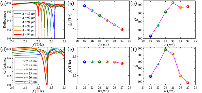
Figure 6. (a), (d) Calculated reflectance spectra, (b), (e) resonance frequency, and (c), (f) Q value of the MIMIMIMI gratings as (a)–(c) the grating period Λ and (b)–(f) grating width vary. The vertical dotted lines in (a), (d) and the horizontal dotted line in (e) indicate RA frequencies determined by equation (1).
Download figure:
Standard image High-resolution imageOn the other hand, figures 6(d)–(f) show that, if the grating width varies whereas the period keeps constant, the resonance frequency keeps almost constant because the RA frequency determined by the period does not change. However, the linewidth first decreases and then increases, corresponding to first increasing and then decreasing quality factor. In other words, the proposed grating is resonant at exactly the RA frequency that is determined by the grating period, and given the grating period, there exists an optimized grating width for achieving the optimal quality factor.
Figure 7 shows three typical optimized sets of grating width and period (w, p) illustrating the tuning of the resonance frequency while keeping high quality factors. For various parameters, the resonance occurs at exactly the RA frequency that is determined by equation (1), as indicated by the vertical dotted lines.By increasing the grating period from 80 µm to 105 µm, the resonance frequency is blueshifted from 2.584 THz to 1.969 THz. By optimizing the grating width, the obtained quality factors can be as high as Q > 400 for these resonances.

Figure 7. Calculated reflectance, transmittance and absorbance spectra of the MIMIMIMI gratings with (a) ( m,
m,  m), (b) (
 m,
m,  m) and (c) (
 m,
m,  m). The vertical dotted lines indicate RA frequencies determined by equation (1).
Download figure:
Standard image High-resolution imageFigure 8 depicts the calculated reflectance spectra of the MIMIMIMI hyperbolic metamaterial grating with different metal or insulator thicknesses while keeping the other parameters fixed. It is clear that there exists a best set of metal–insulator thicknesses,  for achieving the narrowest FWHM and the largest quality factor. For too thin metal or insulator, the RA phenomenon is weak. On the other hand, as the thickness of metal or insulator increases, the resonance is broadened and is slightly shifted to lower frequency.

Figure 8. Calculated reflectance spectra of the MIMIMIMI gratings with (a) different metal thicknesses while keeping  m, and (b) different insulator thicknesses while keeping
  m. The vertical dashed.
Download figure:
Standard image High-resolution image
3. Concluding remarks
In conclusion, we have proposed a novel terahertz sensing platform based on the RA in hyperbolic metamaterial gratings. Both the far-field reflectance/absorbance spectra and the near-field distributions for various multilayered gratings have clearly revealed that hyperbolic metamaterials composed of at least of two pairs of MI multilayers are necessary to achieve the super-high quality factor of Q = 516. We have also shown that this striking performance originates from greatly enhanced electric fields over an extremely large area of the sensing region at the RA frequency. We have shown that the sensitivity reaches 1.56 THz RIU−1 and meanwhile the FOM is up to 355 RIU−1 at the operation wavelength of 2.272 THz. Correspondingly, the normalized sensitivity is as high as 0.69 RIU−1, which is the highest comparing with the reported terahertz sensors based on metamaterials. We have shown that the resonance frequency, which is exactly the RA frequency, can be conveniently scaled by varying the grating period, according to the RA equation. Meanwhile, the quality factor can be as high as Q > 400 if the grating width, the metal and insulator thicknesses are all optimized. Therefore, we expect that high sensing performance can be achieved in other frequency ranges, even in the visible and near-infrared regime by scaling the structure size. As a final remark, we note that although we illustrated our idea with the one-dimensional gratings, similar results are expected to be obtained for two-dimensional gratings [49].
Data availability statement
The data that support the findings of this study are available upon reasonable request from the authors.
Acknowledgment
This work was supported by the Shenzhen Research Foundation (JCYJ20180507182444250), the Shenzhen Institute of Artificial Intelligence and Robotics for Society, and the Natural Science Foundation of Guangdong Province (2022A1515010086).