
Abstract
Transformation optics (TO) has been recognized as an established scheme that can precisely manipulate electromagnetic surface wave propagations. Utilising the advantages of the TO technique, we proposed a TO device which can control the propagation direction of surface waves. The device is based on a generalized Eaton lens and can be realized on curved surfaces. Such a device can be composed of stacked ring layers, where the refractive index of each ring segment can be individually engineered. By engineering the refractive index, the stacked ring structure can guide the propagation direction of the surface wave. It may open a new door to manipulate surface wave propagation on demand.
Export citation and abstract BibTeX RIS
1. Introduction
Transformation optics (TO) establishes the connection between geometry and material properties and has been regarded as a general mathematical method to design optical devices with unusual properties [1–3]. In the last decades, TO have attracted intensive attention because it enables exotic wave propagation. Broad and fascinating applications have been demonstrated, particularly in controlling the direction of electromagnetic (EM) wave propagation, such as cloaking [4–11], metalens [12–15], surface wave guides [16–20], absorbers [21] and whispering gallery mode resonators [22].
In recent years, TO was applied to design surface wave propagation direction controlling devices. One method proposed by Pendry [4] is spatially-varying based on the form-invariance of Maxwell's equations. With the use of the coordinate transformation to the constitutive parameters, the EM field can be manipulated on demand. Such devices usually consist of a metamaterial to fulfill the requirement of anisotropic permittivity and permeability. For example, Huidobro [16] designed a 3D beam shifter to control the propagation of surface waves in which both permittivity and permeability should be anisotropic and constrained precisely. This implies inevitable optical losses and complex nanofabrication techniques which limit the performance of the TO devices. To overcome the requirement of anisotropic materials, one implementation is the quasi-conformal TO proposed by Leonhardt [23]. Quasi-conformal TO has offered an alternative to TO designs using all dielectric materials and has been widely used in numerous applications such as conformal lens [24], Maxwell-fisheye lens [25] and waveguides [26]. However, the quasi-conformal TO method assumes approximations and is limited to omnidirectional sources when directly designing a new lens [3, 27]. Another way, proposed by Hao [6, 19], was based on the Fermat's principle. The required refractive index of the rotationally symmetric curved surface can be calculated by equating the optical path length between a flat plane with homogeneous refractive index and the desired rotationally symmetric curved surface. One of the major advantages of this method is that no simultaneous permittivity and permeability restriction are required. However, an analytical solution is hard to realize in this method which results in the imperfect design of TO devices.
A surface wave is a special type of EM wave and it decays exponentially away from the surface. Guiding surface waves is a classical subject of guided wave theory, which has numerous applications such as antennas and transmission lines [28, 29]. Recently, surface wave direction control devices have been proposed on curved surfaces to avoid complex refractive index distribution [18, 30–34]. However, most of the studies use a numerical approach [30, 34] and full-angle beam-steering devices on curved surfaces have seldom been descried. In this work, we designed a TO device with a rotationally symmetric curved surface to partially control the propagation direction of surface waves. Such a surface wave propagation direction controlling device could be of use in various potential application areas such as waveguides [26] and cloaking [31]. Compared to previous studies [18], the proposed TO device can be realized on multiple curved surfaces, which expands the range of options in application. Analytical solutions for the required refractive index can be achieved on the rotationally symmetric curved surfaces leading to better performance. For experimental realization, we proposed a multi-layer Rinehart surface [35], with discrete refractive index for each designed layer. The proposed devices can bend the surface wave to 45°, 90°, 135° and 180° as a demonstration of full-angle beam bending. This TO method can further increase the design variables with multiple curved surfaces and achieve better performance with analytical solutions.
2. Results and discussion
2.1. The design of surface wave on curved surfaces
Before our simulation work, we assume that all the surfaces considered, as well as their refractive index profile distribution, are rotationally symmetric. Figure 1 illustrates a curved surface generated by rotating the generating curve C, with axis of revolution z in a cylindrical coordinate system. We equate the radial light path L in the flat homogeneous surface with the radial light path in the rotationally symmetric curved surface C [36] as


Figure 1. Illustration of the beam path C (red line) in the rotationally symmetric Rinehart-shaped curved surface which is equated to the beam path L (blue line) in the flat plane.
Download figure:
Standard image High-resolution imagewhere ρ is the distance from the axis z, N(ρ) is the refractive index of the curved surfaces which is a function only of ρ, ![$F\left( \rho \right) = \exp \int_1^\rho {\left[ {{s^{\textrm^^{\prime}}}\left( \rho \right){\textrm{/}}\rho } \right]} {\textrm{ }}d\rho {\textrm{ }}$](https://content.cld.iop.org/journals/0022-3727/54/7/074003/revision4/dabbbb6ieqn1.gif) is the mapping function and s(ρ) is the arc distance measured along C, n[F(ρ)] is the refractive index of the flat surface as a function of F(ρ). By solving equation (1), we can derive the modified index profile N(ρ). Thus, the layered refractive index lens can be mapped onto an arbitrary rotationally symmetric curved surface to manipulate the surface wave on curved surfaces.
is the mapping function and s(ρ) is the arc distance measured along C, n[F(ρ)] is the refractive index of the flat surface as a function of F(ρ). By solving equation (1), we can derive the modified index profile N(ρ). Thus, the layered refractive index lens can be mapped onto an arbitrary rotationally symmetric curved surface to manipulate the surface wave on curved surfaces.
At first, we set angle ϕ as the angle between the reference line i along the incident light and the line o along the output wave propagation, as shown in figure 2(a). Here, we set angle ϕ = 0°, which describes a wave moving forward without bending and ϕ = 180° to represent a retroreflector. A planar surface with refractive index  , which is known as an Eaton lens, can bend the surface wave with an angle ϕ = 180°, where nb
is the background refractive index. An Eaton lens is a typical gradient index lens and offers a general method to control the surface wave. Various applications based on Eaton lens' have been introduced such as an omnidirectional retroreflector [37] and waveguides [38, 39]. Here, we set the background refractive index as air (nb
= 1). This work is simulated with COMSOL, based on the finite element method. In the simulation, we set the radius of the bottom of the curved surface to 1000 nm. A perfect electric conductor boundary is used for the top and bottom of the curved surfaces and the scattering boundary conditions around the edge are used. The input source, polarizing along the z-axis, propagates from the left of the curved surfaces. Based on equation (1), we can bend the surface wave on any rotationally symmetric curved surface. We present four rotationally symmetric curved surfaces, which can bend the surface wave with an angle ϕ = 180°. The simulation, as shown in figure 2(b), is a cone surface which can be described as
, which is known as an Eaton lens, can bend the surface wave with an angle ϕ = 180°, where nb
is the background refractive index. An Eaton lens is a typical gradient index lens and offers a general method to control the surface wave. Various applications based on Eaton lens' have been introduced such as an omnidirectional retroreflector [37] and waveguides [38, 39]. Here, we set the background refractive index as air (nb
= 1). This work is simulated with COMSOL, based on the finite element method. In the simulation, we set the radius of the bottom of the curved surface to 1000 nm. A perfect electric conductor boundary is used for the top and bottom of the curved surfaces and the scattering boundary conditions around the edge are used. The input source, polarizing along the z-axis, propagates from the left of the curved surfaces. Based on equation (1), we can bend the surface wave on any rotationally symmetric curved surface. We present four rotationally symmetric curved surfaces, which can bend the surface wave with an angle ϕ = 180°. The simulation, as shown in figure 2(b), is a cone surface which can be described as  , where kc
is the slope of the cone surface. The analytically solution of equation (1) is
, where kc
is the slope of the cone surface. The analytically solution of equation (1) is
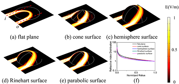
Figure 2. The electric field propagation of Eaton lens with different surfaces, including (a) the flat plane, (b) the cone surface, (c) Rinehart surface, (d) the hemispherical surface, and (e) the parabolic surface. (f) The refractive index distribution of all surfaces mentioned above.
Download figure:
Standard image High-resolution imageand is valid for any slope kc
of the cone surface. Here, we choose kc
= 1.183 to keep the height in the same range as the other surfaces. Although the analytically solution here can perfectly match the refractive index distribution needed to bend the surface wave, the tip of the cone surface results in imperfect propagation. To achieve a better effect of controlling the surface wave, we choose a dome-like top surface for further designs. In figure 2(c), it is a hemisphere surface with arc distance  . The required index for a hemisphere surface can be calculated analytically and is given by
The generalized Rinehart surface is a special type of surface which is hard to describe in a Cartesian coordinate system but easy to express by a generated curve. The arc distance of the generalized Rinehart surface takes the form  , where kr
is a parameter ranging within [0,1]. The generalized Rinehart surface also can be calculated analytically and the refractive index distribution can be expressed as
, where kr
is a parameter ranging within [0,1]. The generalized Rinehart surface also can be calculated analytically and the refractive index distribution can be expressed as

In the simulation shown in figure 2(d), we choose kr
= 1/2 for simple representation. The hemisphere surface is a special situation of the generalized Rinehart surface (kr
= 1). Compared with the generalized Rinehart surface, the parabolic surface with arc length  , where kp
is the parameter of the parabolic surface, can be a more ordinary rotationally symmetric surface. The analytical solution of the parabolic surface to equation (1) is
, where kp
is the parameter of the parabolic surface, can be a more ordinary rotationally symmetric surface. The analytical solution of the parabolic surface to equation (1) is
where  and
and  . To keep the same scale of the models, kp
= 0.63 is chosen in the simulation and the E-field profile is shown in figure 2(e). Even though the parabolic surface is more ordinary, its refractive index expression is complex.
. To keep the same scale of the models, kp
= 0.63 is chosen in the simulation and the E-field profile is shown in figure 2(e). Even though the parabolic surface is more ordinary, its refractive index expression is complex.
To show the propagation direction control of the surface wave, we present simulations of four different curved surfaces which bend the surface wave at different angles ϕ. The general Eaton lens can bend the rays into different angles in the flat plane and can be expressed as [40]

where r is the radius in the polar coordinate system.
For the consideration of the refractive index of the general Eaton lens in a planar surface, we can calculate the refractive index distribution of rotationally symmetric curved surfaces for all angles between 0° to 180°.
Figure 3 shows the simulations with the cone surface, hemisphere surface, Rinehart surface and the parabolic surface which control the propagation direction of the surface wave at angle ϕ = 45°, ϕ = 90° and ϕ = 135°. The incident total electric surface field  from the left is bent though the structure. As can be observed, all simulations with different curved surfaces can control the propagation direction of the surface wave to the specified directions accurately. It is confirmed that the same method can be used for arbitrary rotationally symmetric curved surfaces. Among the simulations above, the structures control the propagation direction of the surface waves at angle ϕ = 90° and ϕ = 180° perfectly, and the output surface waves at angle ϕ = 45° and ϕ = 135° are divergent slightly in figure 3. Based on equation (1), we have the analytical solution of the cone surface, the hemisphere surface, Rinehart surface and the parabolic surface. However, there are no analytical solution to most of the angles in equation (6), and therefore we apply a numerical approach (equation (S1)) to calculate the refractive index distribution N(ρ). The parameters used in equation (S1) are listed in table S1 (available online at stacks.iop.org/JPD/54/074003/mmedia) and the numerical solution of equation (6) and the corresponding fitting results at angle ϕ = 45° and ϕ = 135° are shown in figure S1. Due to the approximate refractive index distribution, the output surface waves at angle ϕ = 45° and ϕ = 135° are not as perfect as the ones at angle ϕ = 90° and ϕ = 180°.
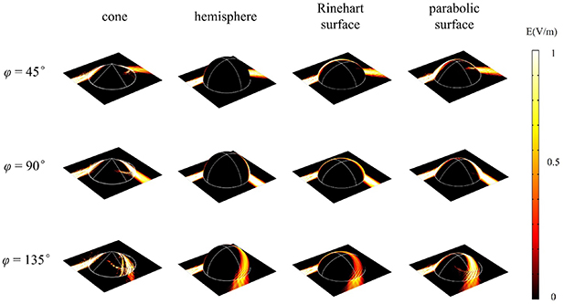
Figure 3. The electric field propagation with continuous cone surface, hemisphere surface, Rinehart surface and parabolic surface which has gradient refractive index distribution. The devices control the propagation direction of the surface wave to different angles including ϕ = 45°, ϕ = 90° and ϕ = 135°.
Download figure:
Standard image High-resolution imageConsidering all the curved surfaces mentioned above, the Rinehart surface has a horizontal tangent plane at ρ = 0, a vertical tangent plane at ρ = 1 and the Rinehart surface is concave down everywhere between ρ= 0 and ρ = 1. The characteristics of the Rinehart surface lead to good performance of direction control of surface wave. The Rinehart surface allows for the balance between the ordinary of the curved surfaces and is convenient for calculation. We take the Rinehart surface for further exploration.
2.2. Multi-layer structure
The corresponding gradient refractive index distribution is hard to realize. For experimental realization of the device, the gradient refractive index distribution is discretized by dividing the Rinehart surface into layers along the z-axis and we set the background refractive index nb = 1 and operation wavelength λ = 500 nm. Every curved layer has equal height in the layered Rinehart surface. Each curved layer in the layered Rinehart surface is given a refractive index according to the gradient refractive index distribution. Comparing the layered Rinehart surface with 10 layers, 20 layers, 30 layers and 40 layers, as shown in figure 4, the layered Rinehart surface needs 40 layers at least to achieve good performance for controlling the propagation directions of the surface waves. However, the 40-layer Rinehart surface is still complex.
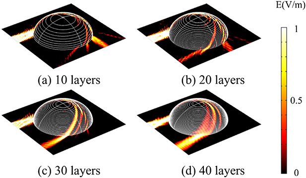
Figure 4. The electric field propagation of an Eaton lens with layered Rinehart surfaces; (a) 10 layers (b) 20 layers (c) 30 layers and (d) 40 layers.
Download figure:
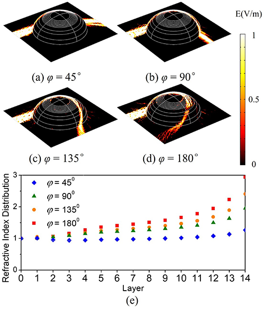
Standard image High-resolution imageConsidering the regularity of the gradient refractive index distribution, we simplify the 40-layer Rinehart surface to 14 layers. The proposed Rinehart surface with 14 layers has fewer layers at the bottom and more layers at the top. As the layers refractive index distribution is stable at the bottom and variable at the top, we combine each 10 layers at the bottom of the 40-layer Rinehart surface into one and each five layers at the middle into one. Each curved layer in the 14-layer Rinehart surface is given a refractive index according to the gradient refractive index distribution. As shown in figures 5(a)–(d), we simulated electric field propagation with the 14-layer Rinehart surface. With a proper refractive index of each layer in the 14-layer Rinehart surface, the devices control the propagation direction of the surface wave at angles ϕ = 0°, ϕ = 45°, ϕ = 90° and ϕ = 135°. The corresponding refractive index of each layer in the 14-layer Rinehart surface used in the simulation are shown in figure 5(e). Compared with the 40-layer Rinehart surface, the 14-layer Rinehart surface is sufficient to achieve the proposed functionalities.
Figure 5. The electrical field propagation with 14-layer Rinehart surface which has distinct refractive index for each layer. The devices control the propagation direction of the surface wave to different angles including (a) ϕ= 45°, (b) ϕ= 90°, (c) ϕ= 135° and (d) ϕ= 180°. (e) The corresponding refractive index of each layer in the 14-layer Rinehart surface. Layer 0 indicates the background (set nb = 1). Layer 1 and Layer 14 indicate the bottom layer and top layer, respectively.
Download figure:
Standard image High-resolution image
3. Conclusion
In summary, we adopted a TO technique to modify the propagation direction of the surface wave on rotationally symmetric curved surfaces. Different types of curved surfaces were investigated. Comparing all the curved surfaces discussed, the Rinehart surface shows good performance of controlling the surface wave in combination with being convenient to calculate. The full angle propagation control has been demonstrated on the Rinehart surface in the visible region. We also proposed a multilayer structure with a dispersed refractive index instead of a continuous gradient refractive index for experimental realization of these devices. The propagation direction of the surface waves can be shifted to 45°, 90° 135° and 180° as a demonstration of full-angle beam-steering. This method provides a useful approach to control the direction of surface waves.
Acknowledgments
This work was supported by National Key Research and Development Program of China (2019YFA0709100) and LiaoNing Revitalization Talents Program (XLYC1807237).
Supporting information
Approximate functions of refractive index distribution for generalized Eaton lens with ϕ = 45°, 135°. The parameters used in the approximate functions and the comparison between numerical solution and fitting result are shown in supporting information. Please see the supplementary material document, available online.