

Abstract
An electrostatic precipitator (ESP) without using corona discharge was investigated herein. The ESP employed a two-stage configuration, consisting of an induction charging-based particle charger and a parallel plate type particle collector. By applying a high voltage of several kV, under which no corona discharge was generated in the charger, particles were charged by induction due to contact with charger electrodes. The amount of charge on the charged particles increased with the applied voltage and turbulent air flow in the charger. Performance of the ESP equipped with the induction charger was investigated using ambient air. The removal efficiency for particles ranging 0.3 µm to 5 µm in diameter increased with applied voltage and turbulence intensity of gas flow in the charger when the applied voltage was sufficiently low not to generate corona discharge. This suggests that induction charging can be used for electrostatic precipitation, which can reduce ozone generation and power consumption significantly.
Export citation and abstract BibTeX RIS
1. Introduction
An electrostatic precipitator (ESP) is a device used to collect particles suspended in air, by utilizing an electrostatic force [1–3]. The ESP was first introduced into the industry about 100 years ago, and is now widely used in many areas, including coal-burning thermal power plants, cement kilns, and steel plants. Further, electrostatic precipitation has been studied for many new applications such as diesel exhaust cleaning and cleaning of indoor air in houses, hospitals, food factories, etc, because it can remove nano- to micro-sized fine particles very effectively with very low pressure drop. Various experimental and numerical works on the application and fundamental phenomena of electrostatic precipitation have been carried out [4–13].
ESP normally uses corona discharge to charge particles. Corona charging is a well-established technique and is widely used in ESP, but it inevitably generates ozone. For some applications of the ESP, such as indoor air cleaning, corona discharge is not preferred because of the ozone generation, which is harmful to human physiology. Another problem with corona charging is the ion utilization factor. The corona charging efficiency is not high enough because not all ions generated by corona discharge are used to charge particles. Most of them simply travel to the collecting electrode without contributing to the charging of particles. Therefore, the energy efficiency of electrostatic precipitation can be improved significantly.
To address these problems, we have studied an alternative method of charging particles based on induction charging [14–17]. It is shown in [18] that induction charging occurs when the surface of a material comes in contact with a charged metal plate. We have studied a two-stage ESP equipped with an induction charger, and showed that particles were removed, whereas corona discharge was not generated in the charger; however, the removal rate was lower than that of a conventional ESP using a particle charger based on corona discharge [19, 20]. The amount of the charge given to the particle is influenced by the electric field. Because induction charging under a higher electric field should give a higher amount of charge [17], to enhance charging characteristics, we examined the use of very fine conductive fibers affixed to the electrode, which concentrates the electrostatic field to the end of the fiber.
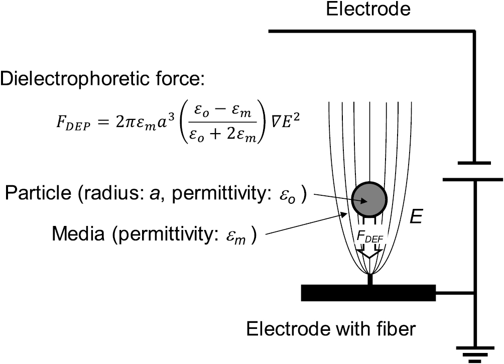
In addition, when an object is placed in a non-uniform electric field, a dielectrophoretic (DEP) force or gradient force is exerted on the object [21, 22]. The DEP force FDEP on a spherical object of radius a and dielectric permittivity εo is
where εm is the dielectric permittivity of the medium and E is the electric field strength [22]. When the dielectric permittivity of the object is larger than that of the medium, the DEP force is exerted on the object in the direction in which the electric field becomes higher. Thus, in this case, particles near the fiber are attracted in the direction of the fiber due to the DEP force [23, 24], which will increase the particle-electrode impact. The fine fibers introduced on the induction charger electrode are effective for yielding high DEP force due to very high  . The electrodes with fibers are also advantageous for particle chargers because the DEP force can act on neutral particles. For these reasons, newly developed particle chargers equipped with charger electrodes with fine fibers should improve charging characteristics, and thus improve collection efficiency of the ESP, not only because of the intense electric field but also because of the DEP force. The effect of DEP force should be more significant for larger particles, as
  increases with particle diameter. From the theory of air filtration, fine fibers fixed on the electrode increase the chance of particles' collision with (or attachment to) the fiber due to inertia, interception, and diffusion compared with an electrode without fibers, which also helps in particle charging. An ESP equipped with the induction charger developed in this study was examined.
2. Experimental
To evaluate the effect of the electric field and particle collision with electrodes on the characteristics of induction charging, a rotating electrode particle charger was used. Figure 1 shows a schematic of the entire experimental setup, which employs a so-called two-stage ESP, in which the particle charger and particle collector were arranged in series. An air blower was used as a charger after modification as follows: a conductive double-faced adhesive tape was applied on the surface of a rotating blade and grounded, to make the blade serve as a grounded electrode. Very thin carbon fibers (approximately 20 µm in diameter) were taped at the furthermost edge of the rotating blade to develop the DEP force in the vicinity of the fibers' edge. The ends of carbon fibers were trimmed, to ensure that the protruding length was 1 mm. As shown in figure 2, particles suspended in air are attracted to the fiber due to the DEP force when a high DC voltage is applied to the charger. As a high voltage electrode, an aluminum tape was applied on the inner surface of the air blower, where the edge of the rotating blade faces. The gap between the high voltage and grounded electrode was approximately 11 mm. The fan speed and throttle valve were controlled to adjust air flow rate and charger rotation speed independently. A microammeter was used to detect corona discharge generation with a significant current value. By applying a high voltage to the housing, a high electric field is induced in the space between the rotating blade and the housing, where air flows. When particles come in contact with either the high voltage or grounded electrode, particles are charged by induction charging.

Figure 1. Schematic diagram of experimental setup.
Download figure:
Standard image High-resolution image
Figure 2. Dielectrophoretic force acting in non-uniform electric field.
Download figure:
Standard image High-resolution imageCharged particles were then introduced to a collector placed downstream. The collector consisted of 25 stainless steel (SUS 304) square plates (320 mm × 120 mm) arranged in parallel, with 6 mm separation. From the top, the plates were grounded and were connected to a DC high voltage power supply altenately. The opening area of the collector was 320 mm × 180 mm. A microammeter was used for the detection of corona discharge in the collector. The ESP experiment was carried out in a room with constant temperature and humidity, which were 20 °C and 50%, respectively. Particles suspended in the air in the room were used to evaluate the collection efficiency of the ESP. The number and concentration of the particles with diameter between 0.3 µm and 5 µm were measured with a particle counter (Model 3905, KANOMAX JAPAN Inc.).
The particle charging characteristics of the newly developed particle charger were estimated in an indirect manner, as shown in figure 3. The air flow from the charger was used to impact the particles suspended in air on an electrically insulated metal plate. When the charged particles reach the plate, the charge should be transferred from the particles to the plate. As a result, the potential of the plate will increase with time and reach a steady state. The saturated value of the potential depends on the amount of charge transferred from the particles. More significantly charged particles will result in a higher potential. The potential of the metal plate was measured with a digital surface potential meter (KSD-2000, KASUGA DENKI INC.), which facilitates non-contact and high impedance potential measurement, to minimize the interference. This charger experiment was also carried out in the same experimental room and under the same conditions as the ESP experiment.
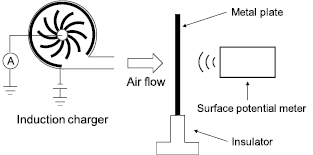
Figure 3. Experimental setup for measuring induction charging characteristics.
Download figure:
Standard image High-resolution image3. Results
Figure 4 shows the electric current of the rotating electrode type particle charger measured for various applied voltages. No significant current was observed regardless of the polarity of the applied voltage when the applied voltage was 4 kV or smaller. When the applied voltage exceeded 4 kV, the current increased with applied voltage, suggesting that application of a voltage larger than 4 kV generated corona discharge.
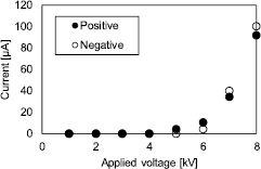
Figure 4. I–V characteristics of the rotating electrode type induction charger.
Download figure:
Standard image High-resolution imageThe particle charging characteristics of the newly developed induction charger were investigated. Figure 5(a) shows the correlation between the measured potential and voltage applied to the charger. The air flow velocity was 1.5 m s−1 at charger outlet, and electrode rotating speed was 3300 rpm. From figures 5(a) and (b), it can be seen that the potential on the metal plate increased with voltage applied to the charger, even when the applied voltage was smaller than 4 kV, where no corona discharge was generated. This suggests that particles were charged by induction charging without corona discharge, and that charged particles passed out of the charger, which means that the induction charger can be used for two-stage ESPs. The polarity of the applied voltage did not affect induction charging characteristics significantly. The measured potential increased nearly proportionally to the applied voltage for both positive and negative voltage applications. This is advantageous because it means that the induction charger works even when the applied voltage is lower than the corona onset voltage. The potential increased with applied voltage in similar manner, independent of the occurrence of corona discharge, suggesting that ions were not emitted from the charger.

Figure 5. Characteristics of induction charging (a) potential versus applied voltage, (b) potential versus rotating speed.
Download figure:
Standard image High-resolution imageFigure 5(b) shows the effect of the rotating speed of the charger electrode on the charging characteristics, when both applied voltage and air flow were maintained at the same value. The measurement was taken with a constant applied voltage of 4 kV. The electrode rotation speed was changed, but air flow velocity at the charger outlet was kept constant at 1.5 m s−1 by adjusting a throttle valve located at the charger inlet. On the whole, the measured potential increased with rotating speed. The measured potential was 0 V for negative voltage application at a rotating speed of 1500 rpm. This is probably because of the round-off error, as the minimum scale value of the potential meter was 0.1 kV. An increase in the rotating speed of the electrode with the air flowing at the same velocity means an increase in the electrode to particle relative velocity. As a result, the number of electrode–particle impacts should increase with the rotating speed. Turbulence, which is also affected by the electrode rotating speed, can be another factor that affects the induction charging. In conclusion, from the results in figure 5, it is highly probable that the particles were charged by induction charging when the applied voltage was smaller than the corona onset voltage.
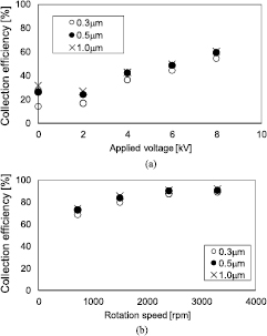
Figure 6 shows the particle collection efficiency when the same charger as above was used. Figure 6(a) shows the collection efficiency when the electrode rotating speed was 720 rpm and the air flow velocity was 2.0 m s−1 at the charger outlet and 2.8 cm s−1 in the collector. The particle residence time in the collector was approximately 4.3 s. The voltage applied to the collector was 4 kV, with which no corona discharge was generated in the collector because no current was detected by a microammeter. The collection efficiency increased nearly linearly with the applied voltage in the low voltage region (where no corona discharge was generated) and the high voltage region (where corona discharge was generated). This result agrees with the above-mentioned results that particles were charged by induction charging without corona discharge. Larger particles showed slightly higher collection efficiency. This could be because larger particles are more likely to collide with electrodes due to larger inertia. Another reason for the slightly higher collection efficiency for larger particles could be larger DEP force for larger particles (equation (1)).
Figure 6. Collection efficiency of electrostatic precipitator using induction charging. (a) Collection efficiency versus applied voltage, (b) collection efficiency versus rotating speed.
Download figure:
Standard image High-resolution image
Figure 6(b) shows the collection efficiency when the charger voltage was +4.5 kV and air flow velocity was 1.5 m s−1 at the charger outlet and 2.3 cm s−1 in the collector. The particle residence time in the collector was approximately 5.2 s. The voltage applied to the collector was 4 kV. Under these conditions, corona discharge was not generated in the charger or in the collector because the current was below the measurable limit of the microammeter (<0.1 µA). Collection efficiency increased with increasing electrode rotating speed, which is qualitatively in agreement with the result of the charging characteristics in figure 5(b). However, while the collection efficiency when the charger voltage was 4.5 kV and air flow velocity was 1.5 m s−1 was approximately 70% (from figure 6(b)), charging was very weak when the charger voltage was 4 kV and the air flow velocity was 1.5 m s−1 (from figure 5(b)). This discrepancy of charging characteristics and collection efficiency could be accounted for by bipolar charging. If we assume that induction charger is applied with a positive high voltage, the particles are charged positively and negatively by colliding with the high voltage electrode and grounded electrode, respectively. Both positively and negatively charged particles can be collected by the collector, resulting in high collection efficiency. On the other hand, the above-mentioned estimation of the charging characteristics is valid for net charge. Therefore, a large discrepancy between the estimated charging characteristics and collection efficiency suggests that the induction charger used in this study works as a bipolar charger with a relatively good charge balance.
4. Discussion
Induction charging is a process wherein electrons are added to or removed from an object when the object comes into contact with an electrode where an electric field is present. The added charge moves into the object and accumulates on its surface as charging current flows. The amount of charge on the object increases with time and saturates. The amount of saturated charge is determined only by the electric field and particle diameter [16, 17]. Nader et al carried out numerical simulations on induction charging of a core–shell type spherical particle to study the effect of various parameters such as contact area, conductivity of the surface layer, particle permittivity, and surface layer thickness. Charging time significantly decreased with the contact area and conductivity of the surface layer. When the conductivity of the surface layer is higher than that of bulk, which is often true in practical situations due to the humidity in air, charging time decreases with surface layer thickness [16].
As a result, the charging time decreased with decreasing the total resistance of the circuit, consisting of the surface resistance of a particle and contact resistance between the electrode and particle. It is difficult to discuss the results obtained in this study in relation to the electrical properties of the particles because particles in the laboratory air were used for the experiment, and detailed properties of the particles were unknown; however, it is probable that charging time was short enough to charge the particles because high removal efficiency was obtained by electrostatic precipitation. It is also reasonable that the particles were sufficiently conductive because more conductive particles can be charged faster by induction, and thus, for the same contact time, the amount of charge on the particle should be larger when the particle is more conductive.
In principle, the particles move along a streamline. However, because the air flow in the charger is highly turbulent, the particle's motion is affected by inertia, resulting in deviation from the gas streamline, which increases the impact of the particles on the electrode. Electrostatic forces such as Coulomb's force and the DEP force should be considered as well. When a particle is charged, Coulomb's force toward the electrode having the opposite polarity is exerted on the particle. As described earlier, the DEP force in the direction of the fiber is exerted on particles. Both electrostatic forces increase the particles' impact on the electrodes in the charger leading to higher charging of the particles. The DEP force is especially effective for charging airborne particles, which are normally neutral, because the DEP force can act on uncharged particles.
In addition to induction charging and corona charging, particles can be charged by triboelectric processes. Triboelectric charging takes place when an object comes in contact with another object and is then detached assuming that the two objects have different work functions. Theoretically, it is possible that particles are triboelectrically charged by friction with air, the electrode, and the fiber, but in the experimental conditions in this study, the effect of triboelectric charging was probably negligible because the collection efficiency was very low when the voltage applied to the induction charger was zero.
Particles probably collide with the high voltage and grounded electrodes repeatedly because once a particle is positively or negatively charged, it drifts towards the cathode or anode, respectively. The highly turbulent nature of the air flow in the charger will further increase the particle's impact on the electrodes. As a consequence, the amount of charge in a particle, along with its polarity, is primarily determined by the last collision the particle makes in the charger. Therefore, it is preferable that the full electrode surface should be modified with fibers, which enhances the probability of collision hydrodynamically and electrostatically (DEP force), as well as increases the amount of induced charge due to the highly converged electric field.
5. Conclusion
This paper describes the feasibility of induction charging for charging particles suspended in air, with the intention of application to electrostatic precipitation by examining the experimental parameters and construction of the induction charger. Airborne particles were able to be charged by induction charging without corona discharge generation. The charging characteristics were significantly affected by electric field strength and air flow in the induction charger. Fine particles, ranging from 0.3 µm to 5 µm in diameter, were successfully collected by a two-stage ESP equipped with the induction charger in place of a particle charger, based on corona discharge widely used in conventional ESPs. Although the potential use of the induction charging as a particle charger for the ESP was shown, further study is required to improve energy efficiency and charging characteristics under high air flow conditions.
Acknowledgment
The authors are grateful to Mr Hiroshi Hosono, Mr Hikaru Murata, Mr Yuki Iizuka, Mr Hiroshi Yahata, and other members of Engineering Department of Tunnel Ventilation Systems, Panasonic Ecology Systems Co., Ltd Japan. This work was partly supported by JAPS KAKENHI Grant No. JP 15K13928 and JP15H03929.