

Abstract
This paper proposed a rapid fabrication process for polymethylmethacrylate (PMMA) microfluidic mixer chip by non-isothermal method based on resistance heating principle, and the prepared microfluidic mixer chip was successfully applied to the portable pesticide residue detection device. Firstly, the creep test of PMMA was carried out and the six units Maxwell constitutive model was fitted by Prony series. Secondly, the resistance heating device was designed, the influence of current on heating temperature and heating time was investigated, the effect of current on energy consumption was analyzed. Thirdly, the non-isothermal molding simulation and experiment of PMMA were carried out, the quality of PMMA microfluidic mixer chip fabricated by non-isothermal molding was investigated. Finally, the microfluidic mixer chip was adopted to the designed pesticide residue detection device, and the detection sensitivity of the device is 0.0375 mol−1. The research results provide a reference for the efficient preparation of microchannels and the development of portable detection equipment.
Export citation and abstract BibTeX RIS
1. Introduction
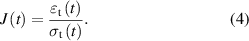
Recently, food safety has become a public safety issue that has been widely concerned, pesticide residue in food is one of the main factors affecting food safety [1–3]. Exploring efficient and sensitive portable pesticide residue methods has become a research hotspot. The portable pesticide residue detection device based on microfluidic mixer chip and photoelectric detection principle is a feasible agricultural residue detection scheme. Particularly, microfluidic mixer chip can greatly improve the mixing efficiency during detection process and greatly reduce the consumption of detection reagents. Compared with paper-based microfluidic mixer chip, the polymethylmethacrylate (PMMA) material has the advantages of high strength, good light transmittance, good heat dissipation and good insulation, which promoted the reliable detection accuracy [4]. The traditional fabrication methods for microfluidic chips mainly include material removal methods represented by cutting, the forming method represented by injection molding and compression molding, special processing technology represented by photolithography and plasma etching processing, and additive manufacturing technology. The above four processing methods have their own advantages and disadvantages in preparing microfluidic chips [5–7]. It has been proved that the injection and molding methods are the ideal choices for the fabrication of microfluidic chips [8]. However, the above processing methods need to fabricate the PMMA preform above the melting or conversion temperature, which consumes a lot of energy. In addition, the increase of temperature also brings challenges to the durability of the mold. Therefore, it is necessary to develop a new microfluidic mixer chip preparation method with high efficiency, low resource consumption and low equipment requirements.
Microfluidic mixer technology has made some progress in the pesticide residue detection field. Yang et al [9–12] proposed a photoelectric detection method of pesticide residue detection based on paper-based microfluidic mixer chip, and studied the influence of light source, chip placement angle and temperature on the detection effect, which provided a basis for the portability and generalization of pesticide residue detection. Ye et al [13] developed a disposable centrifugal microfluidic mixer chip for rapid pesticide residue detection based on the principle of enzyme inhibition and photometric analysis. The microfluidic chip was solidified by polydimethylsiloxane, which improved the detection precision and speed. Microfluidic chips for pesticide detection should not only have good consistency, but also have excellent light transmission performance. Its high-efficiency and low-cost processing is the focus of current research. Zhang et al [14] proposed a pesticide residue detection device, the microfluidic mixer chip adopted on the device was prepared by 3D printing, the reagent mixing speed was accelerated by the microfluidic mixer chip, but the optical performance of the printed chip limited the improvement of the accuracy of the device. Qin et al [15] proposed a microfluidic mixer chip manufacturing method based on laser cutter, which greatly accelerated the preparation efficiency. Liu et al [16, 17] conducted intensive research on the rapid heating molding method and provided ideas for the rapid molding preparation of microfluidic mixer chips, which included that the finite element method simulation method was used to explain the temperature change of graphene coating and the heat transfer between graphene and PMMA under the condition of local rapid heating, as well as the use of precision steel ball and diamond slurry on silicon mold to create microlens with precise geometry combined with flapping method and rapid prototyping method. The above analysis proved that the combination of microfluidic technology and photoelectric detection technology can greatly improve the detection accuracy of pesticide residues, but the high-precision and efficient processing of microfluidic chip still needs to be paid attention to. In addition, high optical performance is the premise to ensure the detection accuracy of the device.
Based on the above analysis, this research proposed a resistance heating method to realize the non-isothermal molding of PMMA microfluidic mixer chip, and the microfluidic mixer chip has been successfully applied in the portable pesticide residue detection device. The resistance heating device reduced the requirements for equipment and was friendly to small batch processing. The non-isothermal heating method means that the heat affected zone of the PMMA preform was only the area to be deformed, which greatly reduced the heating and cooling time, while the thermal impact on the mold as well as the energy consumption was decreased, correspondingly. Firstly, the creep test of PMMA was carried out and the Maxwell constitutive model was fitted by Prony series to simulate the non-isothermal molding process of PMMA. Secondly, the resistance heating device was designed, and the influence of current on heating temperature and heating time was investigated through calculation, simulation and experiment, respectively. The effect of current on energy consumption was analyzed. Thirdly, the non-isothermal molding simulation and experiment of PMMA were carried out, the precision of microchannel contour obtained by molding was compared. Finally, the microfluidic mixer chip was applied to the designed pesticide residue detection device, and the detection sensitivity of the device was investigated. The research results provide a reference for the efficient preparation of microchannels and the development of portable detection equipment.
2. Experimental section
2.1. Viscoelastic model construction of PMMA material
The Maxwell model is the most suitable model to describe the deformation law of PMMA at high temperature, which has been discussed many times in our previous studies [18–22]. In order to accurately fit the parameters in the model, it is necessary to carry out creep test to obtain the creep curve of PMMA with time under constant pressure.
The cylindrical compression method was used to test the creep curve of PMMA. The radius  and height
  of the designed PMMA cylinder are 6.9 mm and 2.6 mm, respectively. The schematic diagram of PMMA change before and after molding is shown in figure 1. The roughness of mold surface and PMMA surface was controlled within 10 nm, and the change of contact area caused by friction between contact surfaces can be ignored. Therefore, the change of contact area during creep test mainly comes from the change of compression. According to the principle of constant volume, assuming that the height of the PMMA sample is H(t) at time t, the real strain and real stress can be expressed as,
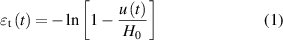
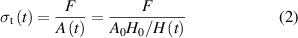

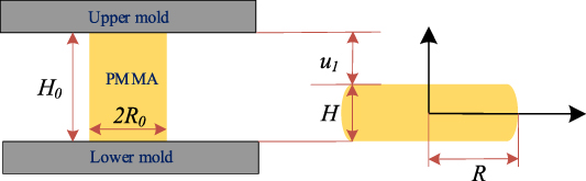
Figure 1. The schematic diagram of PMMA change during creep test.
Download figure:
Standard image High-resolution imagewhere,  is the uniaxial compression displacement recorded by the test equipment,
  is the average contact area of the sample.
The creep compliance of the PMMA  can be obtained,
By Laplace transform, the creep compliance in the complex domain can be obtained as follows,
where, s is a complex variable.
After Laplace transform, the uniaxial relaxation modulus in the complex domain can be deduced as,
Further, it is deduced that the shear relaxation modulus of glass in the complex domain is,
The inverse Laplace transform was performed on equation (7) to obtain the shear relaxation modulus G(t) in the time domain. The relaxation modulus is usually represented by Prony series in commercial finite element software. The five-branch generalized Maxwell model was adopted to fit the shear relaxation modulus to obtain the shear relaxation modulus G(t) in the form of Prony series. The shear relaxation modulus G(t) in the form of Prony series was obtained as follows,
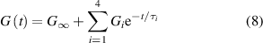
where, G∞ is the long-term shear modulus of PMMA, Gi, βi and τi represent the shear modulus, shear viscosity and shear relaxation time of the Maxwell unit, respectively.
In addition, the Williams-Landel-Ferry (WLF) equation was adopted to describe the deformation behavior of PMMA in non-isothermal state [23],
where,  is a translation factor, which describes the time–temperature equivalent characteristics of PMMA,
  and
and  are constants of PMMA material at a given reference temperature
  , respectively.
2.2. Design and calculation of heating device based on resistance heating principle
In order to improve the preparation efficiency of microfluidic mixer chips and reduce the preparation energy consumption, a non-isothermal molding equipment based on resistance heating principle was developed. As shown in figure 2(a), the designed resistance heating device includes aluminum alloy mold, resistance heating sheet, thermocouple temperature sensor, temperature testing device and DC control power supply. Due to the excellent thermal conductivity of the aluminum alloy mold, the heat generated by the resistance heating sheet will be quickly transmitted to the PMMA surface. In order to improve efficiency, two rows with six resistance heating sheets were arranged on the mold. The thermocouple on the mold surface was used to monitor the heating temperature of the mold, while the current of the DC control power supply can be adjusted to meet different heating requirements, the developed device is shown in figure 2(b).
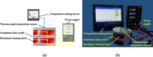
Figure 2. Schematic diagram of resistance heating device (a) and the developed device (b).
Download figure:
Standard image High-resolution imageThe heat  generated by the resistance heating sheet can be expressed as [24],

where,  is the input current, R is the resistance value of the electric heater, and t is the heating time, λ is the heat transfer coefficient between the resistance heating sheet and the aluminum alloy mold.
The heat  transferred to the aluminum alloy can be expressed as,

where,  is the specific heat capacity of the mold and
  is the quality of the mold.
So, the relationship between input current and mold temperature increment  can be expressed as the following formula,
where,  is the heat transfer efficiency.
The diameter and height of the aluminum alloy cylinder mold are 80 mm and 50 mm, and the weight of the mold is 0.6875 kg. The resistance heating sheet was composed of a resistance heating wire and a mica sheet. The resistance heating wire was wrapped by the mica sheet. The heating power was determined by the resistance of the resistance heating sheet and the input current. When energized, the resistance heating wire generated heat due to the electrothermal effect and transferred it to the bonded mold. The size of the resistance heating sheet is 49 mm × 19 mm, and its thickness is 0.2 mm. The thermophysical parameters of mold and resistance heating sheet are shown in table 1. By substituting the data into the formulas (10)–(12), the maximum temperature that can be obtained with different input currents and the heating time under steady state can be estimated.
Table 1. The thermophysical parameters of mold and resistance heating sheet.
Specific heat capacity of aluminum alloy ( ) ) | Heat transfer coefficient of aluminum alloy mold ( ) ) | Resistance of resistance heating sheet (Ω) | Maximum power of resistance heating sheet (W) | Input current (A) |
|---|---|---|---|---|
| 896 | 0.30 | 7.2 | 20 | 1/1.3/1.5/1.8 |
2.3. Simulation and experiment of non-isothermal molding process of microfluidic mixer chip
The traditional isothermal heating and the non-isothermal heating process based on electrothermal resistance effect were simulated. The temperature displacement coupling method was applied in the traditional isothermal heating simulation of molding. A 6061 aluminum alloy metal block with a diameter of 80 mm and a height of 50 mm was adopted to the experiments. The upper and lower mold sizes kept the same. The microfluidic chip is a PMMA sample with a length of 68 mm, a width of 19 mm and a height of 1.5 mm. The PMMA microfluidic chip was placed between the upper and lower mold, and heated to 120 °C, the heating pressure was 250 N. During the non-isothermal process, only the lower mold was heated. When the heat affected zone was larger than the microchannel depth, the microfluidic chip can be fabricated by molding process. Except that the heating method is inconsistent, other molding parameters of non-isothermal molding method was consistent with isothermal heating method.
The detailed structure of the designed microfluidic mixer chip is shown in supplied figure 1 in the supplied material. The microfluidic mixer chip includes two inlets, mixing channel, liquid storage tank and outlet. The color reaction was based on the Ellman method [25–28]. Under the catalysis of acetylcholinesterase (AChE), the thioacetylcholine iodide was hydrolyzed into thiocholine and acetic acid. The thiocholine reacted with 5, 5'‐dithiobis (2‐nitrobenzoicacid) to form a yellow product. The higher the AChE activity, the darker the color of the reagent after reaction. By contrast, AChE activity was inhibited and the color of reagent was lighter. The two inlets were respectively filled with the liquid to be tested and the test reagent. The simulation results of fluid mixing concentration in microchannels is shown in supplied figure 2, the fluid was uniformly mixed in the microchannel. After the samples were continuously mixed in the microchannels, the chromogenic liquid was obtained in the liquid storage tank. The mold of microfluidic chip was machined by milling with a micromilling cutter tool, the front angle of the tool is 10°, the back angle is 5°, and the arc radius of the tool tip is 6 μm. The cutting thickness is 0.5 mm and the cutting speed is 0.5 m s−1. Figure 3(a) is the overall structure of fabricated microfluidic mixer chip mold and the figures 3(b)–(d) show the microscopic structure of microchannels in different parts on the mold surface. The observation results indicate that the prepared mold has high surface quality and consistency.
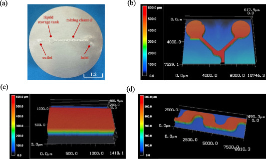
Figure 3. The fabricated microfluidic chip mold (a) and the microchannels on the mold surface at different position (b)–(d).
Download figure:
Standard image High-resolution image2.4. Construction and test of pesticide residue detection device
A pesticide residue detection device based on microfluidic chip was designed, and the light reflection principle was adopted to reflect the concentration of pesticide residue, the schematic diagram of the pesticide residue device is shown in figure 4(a), the device was composed of light‐emitting diode (LED) light source (Jinxin Photoelectric Technology Co., Ltd, Guangzhou, China), precision current source (Shenzhen wave particle Technology Co., Ltd, Shenzhen, China), precision voltage source (Shenzhen wave particle Technology Co., Ltd, Shenzhen, China), silicon photodetector (Shanghai Bose Intelligent Technology Co., Ltd, Shanghai, China) and multimeter. Figure 4(b) is the developed device, the shell of the device was made of opaque black resin fabricated by a 3D printing machine to reduce the influence of external light on the detection accuracy. The LED light source controlled by the precision current source irradiated the liquid storage tank of the microfluidic chip through the optical channel. The light was reflected by the reagent after the color reaction, and was guided by the optical channel and emitted to the silicon photodetector controlled by the precision voltage source. The silicon photodetector converted the light intensity into voltage information and reflected it on the multimeter. When the pesticide concentration is high, the color reaction is shallow and the light reflection is low, resulting in a lower voltage value. On the contrary, the multimeter displays a higher voltage value. Therefore, the pesticide concentration can be obtained indirectly by obtaining the voltage.
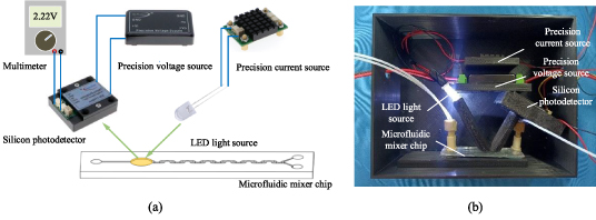
Figure 4. Schematic diagram of the pesticide residue detection device (a) and the developed device (b).
Download figure:
Standard image High-resolution imageThe phosphorus pesticides account for 85% of the domestic market and are the main components of pesticide residues on the epidermis of vegetables and fruits [29, 30]. Therefore, the detection of phosphorus pesticides is particularly important. In addition, there are corresponding standards for the detection limits of various phosphorus containing pesticides. Generally, according to GB 2763-2021, the residue standard in fruits and vegetables is 0.05 mg kg−1 [31].
The detection limit of the pesticide residue detection device  is determined by the following formula [32],
where,  is the confidence factor, usually taken as 3 [33–35],
  is standard deviation of data obtained from multiple measurements,
  is the standard voltage corresponding to a given concentration,
  is the average value of data obtained from multiple measurements.
2.5. Characterizations
In the experiment, the two solvents were pushed into the microfluidic mixer chip channel through the syringes driven by a micro injection pump (XFP02‐B, Suzhou iFLYTEK Scientific Instrument Co., Ltd, Suzhou, China), the liquid flow rate was controlled by micro injection pump. The three‐dimensional structure of the chip was designed by SOLIDWORKS (Dassault Systèmes Corp, Massachusetts, USA) software. The MATLAB 2018 (Mathworks Inc. Natick, Massachusetts, USA) software was used to obtain the viscoelastic constitutive model parameters. The dynamic temperature-displacement module and dynamic implicit module in ABAQUS (Dassault Systèmes Corp, Massachusetts, USA) software were adopted to predict the temperature rise of mold and the deformation law of PMMA during non-isothermal molding process, respectively. The resistance heating sheets (Dongtai Zhenglong Electrical Technology Co., Ltd, Jiangsu, China) were uniformly bonded along the circumference of the mold. In order to analyze the deformation law of resin under non-isothermal conditions, the variation curve of PMMA elastic modulus with temperature was measured by impulse excitation technique with a high temperature elastic modulus tester (IET-1600VP, Beijing Tongde venture Technology Co., Ltd, China). The change curve of PMMA modulus with temperature was obtained by impulse excitation method with a high temperature dynamic elastic modulus testing machine (IET-1600P, Luoyang Zhuosheng Testing Instrument Co., Ltd, China). A laser confocal microscope (KEYENCE Corp, Osaka, Japan) was adopted to measure the 3D profile of the mold and the microfluidic mixer chip fabricated by the non-isothermal molding.
3. Results and discussion
3.1. Parameter fitting of viscoelastic constitutive model
The PMMA exhibits viscoelastic mechanical behavior when heated above the conversion temperature (Tg), and the creep rate is closely related to the temperature change. So, the purpose of testing the creep rate is to accurately predict the deformation law of the PMMA under non-isothermal conditions. The creep test of the PMMA at the temperatures of 120 °C, 125 °C and 130 °C were carried out, and the applied pressure was 250 N. In order to fully heat the PMMA, the holding time was set to 15 min to ensure that the heating softening zone of the PMMA was larger than the microchannel height of the microfluidic mixer chip. The creep curves at three temperatures were obtained, and the six units generalized Maxwell constitutive model was fitted, the fitted Maxwell constitutive model parameters are listed in table 2. The WLF equation parameters  and
and  is 9.3 and 95.9, respectively.
Table 2. The fitted Maxwell constitutive model parameters.

|

|
|---|---|
| 0.1036 | 1.412 |
| 0.000 7447 | 1.304 |
| 0.005 53 | 19.39 |
| 0.8853 | 0.2485 |
| 0.022 64 | 0.022 |
Figure 5 is the PMMA sample obtained before and after the test. It can be found that the increase of temperature increases the creep velocity of the PMMA, and the PMMA diameter is larger at higher temperature. Figure 6 is the comparison of creep curves and fitted curves at different temperatures, the curve fitting is based on the principle of least square method. The results show that the fitting accuracy is high, and the fitting standard deviation reaches 98.5%.

Figure 5. The PMMA sample obtained before and after creep test at different temperatures.
Download figure:
Standard image High-resolution image
Figure 6. Comparison of creep curves and fitted curves at different temperatures.
Download figure:
Standard image High-resolution image3.2. Influence of input current on mold heating time
Figure 7 shows the response curve of input current on mold temperature rising. The length, width and height of PMMA preform are 68 mm, 20 mm, 1.5 mm, respectively. It can be found that with the increase of current, the time for the mold to reach the stable temperature gradually shortens. When the current is 1.5 A, the stable temperature obtained by driving the resistance heating sheet has reached the molding temperature of the PMMA. Furthermore, the results show that the simulation and test results are close to each other, which verifies the accuracy of the simulation. The simulation results lay a foundation for the follow-up study of the deformation law of PMMA under non-isothermal state.
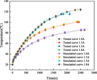
Figure 7. Schematic diagram of influence of input current on heating time.
Download figure:
Standard image High-resolution imageAfter calculation, the energy consumption of molding at 120 °C for 1 h with the traditional molding method is 3.6 × 10³ kJ, while the 1 h energy consumption of the self-developed resistance heating device is only 564 kJ with an input current of 1.5 A, the energy consumption at the input current of 1.8 A is 784 kJ. Therefore, the overall working energy consumption of the resistance heating device is significantly lower than that of the traditional molding processing equipment, the energy used is only 15.67% of the traditional way, and the working current at 1.5 A is the most energy-saving scheme.
Figure 8 shows the effect of temperature rise on elastic modulus of PMMA obtained by impulse excitation technique. When the resin temperature is greater than 100 °C, the instantaneous elastic modulus is lower than 1000 MPa, which can keep the corresponding molding stress at a low value to protect the mold from damage.

Figure 8. The effect of temperature rise on elastic modulus of PMMA.
Download figure:
Standard image High-resolution imageThe superiority of non-isothermal molding was to heat the temperature of the deformation zone to a predetermined temperature, while the non-deformation zone can maintain a relatively low temperature. In order to improve the molding efficiency and reduce energy consumption, heating simulation was implemented, which aims to accurately control the deformation zone of the PMMA preform during the non-isothermal process to fabricate the microchannels. Figure 9(a) is the temperature distribution inside the PMMA in height direction during non-isothermal heating process. The distance in the figure 9(a) represents the distance from the resin to the surface of the heating mold. In the direction away from the heating mold, the temperature decreases continuously, and the depth range suitable for molding is 0.3 mm, which is greater than the height of chip microchannel.
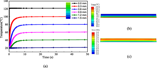
Figure 9. The temperature distribution inside the PMMA in height direction (a) and the compression deformation response of resin in non-isothermal state (b) and (c) during non-isothermal heating process.
Download figure:
Standard image High-resolution image3.3. Influence of molding process on fabricated microfluidic mixer chip accuracy
The microfluidic mixer chip prepared by the electric heating device is shown in figure 10(a). It can be found that the microchannel structure on the mold surface was uniformly copied to PMMA surface, no cracks were observed on the molded PMMA material. The contour comparison of microchannel on the surface of mold and chip is shown in figure 10(b), the results show that the developed non-isothermal molding based on resistance heating method has achieved high replication accuracy.
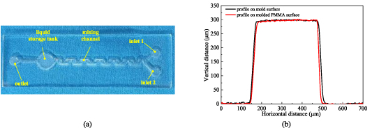
Figure 10. The microfluidic mixer chip fabricated by the developed non-isothermal molding (a) and the contour comparison of microchannel on the surface of mold and microfluidic chip (b).
Download figure:
Standard image High-resolution image3.4. Detection accuracy of pesticide residue device
Figure 11 shows the relationship between induced voltage and pesticide concentration in pesticide residue detection. The average value of three pesticide tests of each concentration was linearly fitted as y = −0.278x + 2.778. The correlation coefficient reached 0.997. The derived evaluation sensitivity is 0.0375 mol−1, which is lower than our previous studies [22]. The reason for this result is considered that PMMA has better optical performance. The fitted results show that the experimental data have a strong linear relationship, which indicates that the microfluidic mixer chip prepared by the electric heating device has the characteristics of high precision, high transparency and high transmittance.

Figure 11. Relationship between induced voltage and pesticide concentration.
Download figure:
Standard image High-resolution image
4. Conclusions
This research proposed a rapid fabrication process for PMMA microfluidic mixer chip by non-isothermal method based on resistance heating principle, and the prepared microfluidic mixer chip was successfully applied to the portable pesticide residue detection device. Here are some conclusions,
(a) The creep behavior of PMMA was tested, and the constitutive model was successfully fitted, which realized the accurate prediction of non-isothermal deformation of PMMA.
(b) Based on the principle of resistance heating, the mold can be heated and the microfluidic mixer chip can be non-isothermally prepared. Compared with the traditional heating method, the energy-saving efficiency reaches 84.33%, and the green environmental protection benefit is improved.
(c) The pesticide residue detection device has been developed, and the detection sensitivity of the device is 0.0375 mol−1. The detection accuracy and sensitivity are effectively guaranteed.
Acknowledgments
This work has been financed by the China Postdoctoral Science Foundation (2019M653761), Provincial Innovation and Entrepreneurship Training Program of Northwest A&F University (S201910712099), the Fundamental Research Funds for the Central Universities (2452018091), Shaanxi Province Science Foundation for Youths (2022JQ-4l7), Shaanxi Province Science Foundation for High-level Talents (f20221008).
Data availability statement
The data that support the findings of this study are openly available at the following URL/DOI: 0000-0002-0025-4356.
Supplementary data (0.1 MB DOCX)