
Abstract
A novel electromagnetic pendulum energy harvester with mechanical motion rectifier (MMR) is proposed and investigated in this paper. MMR is a mechanism which rectifies the bidirectional swing motion of the pendulum into unidirectional rotation of the generator by using two one-way clutches in the gear system. In this paper, two prototypes of pendulum energy harvester with MMR and without MMR are designed and fabricated. The dynamic model of the proposed MMR pendulum energy harvester is established by considering the engagement and disengagement of the one way clutches. The simulation results show that the proposed MMR pendulum energy harvester has a larger output power at high frequencies comparing with non-MMR pendulum energy harvester which benefits from the disengagement of one-way clutch during pendulum vibration. Moreover, the proposed MMR pendulum energy harvester is broadband compare with non-MMR pendulum energy harvester, especially when the equivalent inertia is large. An experiment is also conducted to compare the energy harvesting performance of these two prototypes. A flywheel is attached at the end of the generator to make the disengagement more significant. The experiment results also verify that MMR pendulum energy harvester is broadband and has a larger output power at high frequency over the non-MMR pendulum energy harvester.
Export citation and abstract BibTeX RIS
1. Introduction
Energy harvesting from ambient vibration has been investigated intensively in recent years. One of the most popular ways to harvest vibration energy is using piezoelectric materials [1, 2]. The piezoelectric material has been widely used to harvest energy from various vibration source [3–5] and studied both by theory and experiment [6–8]. Another popular way to harness vibration energy is to drive an electromagnetic generator by designing different motion conversion system. This type of design can be either single degree of freedom [9–11] system or multi-degree of freedom system [12]. Most vibration energy harvesters are designed as linear resonators to achieve optimal performance by matching their resonance frequencies with the excitation frequency [9, 10]. An electromechanical power generator to convert vibrations to electrical energy with electromagnetic transducer is proposed by Marioli et al [13]. Rahimi et al [14] proposed a compact energy harvesting system with an electromagnetic generator and AC–DC converter with frequency up-conversion technique. Zuo et al [15] designed a retrofit regenerative shock absorber which uses electromagnetic effect to convert mechanical energy into electrical energy. An electromagnetic energy harvester to harvest energy from vibration induced by Kármán vortex street is demonstrated by Wang et al [16].
Besides utilizing the translation for energy harvesting, there are also many studies exploring the energy harvesting from rotation. A well-weighted pendulum for energy harvesting from a rotating wheel, consisted of a pendulum and one or more weights, is able to adjust its natural frequency to meet the wheel rotation frequency [17]. Cottone et al [18] investigated a piezoelectric inverted pendulum energy harvester, where on top of the pendulum, a small magnet is added. The excitation is generated by a properly designed magnetic excitation on two small magnets attached near the base of the pendulum. While the pendulum oscillates, the piezoelectric beam is bended and thus generates electrical energy. Mitcheson et al [19] presented a power electronic interface that is capable of continual adjustment of the damping and resonant frequency of a pendulum energy harvester, which is designed for harvesting energy from the rocking motion in a small boat.
In this paper, we proposed and designed two pendulum energy harvesters extracting energy from ambient vibration. The first one is mechanical motion rectifier (MMR) based pendulum energy harvester and the second one is a pendulum energy harvester without MMR. MMR has the capability of converting the bidirectional input motion into unidirectional output rotation. It has been used in several projects [20–23] and proved to be able to improve the efficiency of energy harvester system [23]. The first objective of this paper is to present the design and fabrication of a pendulum energy harvester with MMR. We also designed and fabricated a pendulum energy harvester without MMR as a comparison. The second objective is to investigate the energy harvesting performance of MMR pendulum energy harvester. The dynamic model of MMR pendulum energy harvester is established by considering the engagement and disengagement of one-way clutches in the gear system. The output power of the MMR pendulum energy harvester and non-MMR pendulum energy harvester are studied and compared both numerically and experimentally.
The rest of this paper is organized as follows. In section 2, the design and working principle of MMR pendulum energy harvester and non-MMR pendulum energy harvester are described. In section 3, the dynamic modeling of MMR pendulum energy harvester is established by considering the engagement and disengagement of one-way clutches in the gear system. Simulation results of the MMR pendulum energy harvester and non-MMR pendulum energy harvester are presented in section 4. Experiment verification is demonstrated in section 5. The conclusions are presented in section 6.
2. Design of pendulum energy harvester
In this paper, two pendulum energy harvesters are designed. One is the proposed pendulum energy harvester with an MMR system, and the other one is a traditional pendulum energy harvester without an MMR system. Figure 1(a) shows the design of the non-MMR pendulum energy harvester. A DC planetary generator is connected to a central shaft with a frame. Combined frame and DC generator make a pendulum which rotates along the central shaft under external excitation. A significant advantage of this type of pendulum energy harvester is that it makes full use of the generator weight, and therefore, it is more compact as compared with other pendulum energy harvester designs [24]. To convert motion, two gears are used, one bevel gear is mounted on the central shaft while another is fixed on the motor shaft with set screws. The relative rotational motion between the central shaft and the pendulum body is converted into bidirectional rotation of the generator through engagement between these two bevel gears. One should notice that the generator rotates in two directions during the pendulum motion in non-MMR pendulum energy harvester.

Figure 1. (a) Pendulum energy harvester without mechanical motion rectifier. (b) Proposed pendulum energy harvester with mechanical motion rectifier. (c) Detailed schematic of the mechanical motion rectifier (1. thrust bearing, 2. roller clutch, 3. miter gear, 4. mounting plate, 5. ball bearing, 6. motor shaft, 7. planetary gear heads). (d) Motion of the pendulum under external excitation.
Download figure:
Standard image High-resolution imageFigure 1(b) shows the proposed pendulum energy harvester with an MMR system. The overall design of this MMR pendulum energy harvester is same as non-MMR pendulum energy harvester except for the motion conversion on the central shaft, in which an MMR system is implemented. A detailed schematic of the MMR is shown in figure 1(c). Different from the non-MMR pendulum energy harvester, three bevel gears are used to convert the vibration of the pendulum into generator rotation. Two bevel gears are mounted on the central shaft with two one-way clutches. A one-way clutch is unique in the fact that it transmits torque in one direction only. Here, the two one-way clutches are mounted in opposite directions, meaning that no matter the direction of motion of the pendulum, at most one one-way clutch is engaged at any instant. In this way, the bidirectional motion of pendulum is converted into unidirectional rotation of generator. An important characteristic of this MMR to note is the fact that when the rotational speed of the lower bevel gear, and thus the generator, is larger than that of the bevel gears mounted on the central shaft, both one-way clutches disengage, and no torque is transmitted.
Such an MMR is analogous to an electrical voltage rectifier, where the one-way clutches function as semi-conductor diode, and a fly wheel (generator inertia) acts as the smoothing capacitor. Presented in the simulation and experimental results in sections 4 and 5, the MMR based pendulum has the advantage of high power output at high frequencies as compared to the non-MMR pendulum energy harvester. The natural frequency is also less sensitive to the variation of flywheel mass. Furthermore, the backlash in the gear system is also small since the generator and bevel gears engages in one direction.
3. Model of MMR based pendulum energy harvester
Here, the equation of motion of the proposed MMR pendulum energy harvester in section 2 is derived using the Lagrange method. The equation of motion of the non-MMR pendulum energy harvester is also presented as a comparison. It is known from section 2 that the MMR pendulum energy harvester experiences engagement and disengagement during vibration. Here, we consider the engagement scenario first. A coordinate system is defined in figure 2(b), where the: x-axis is horizontal, y-axis is located on the central axis of the pendulum, and z-axis is perpendicular with x–y plane in a right handed coordinate system. When the overall pendulum is rotating along z-axis, the generator and flywheel rotate along y-axis as well. A harmonic moment  is applied on the MMR pendulum energy harvester as an external excitation. In the engagement scenario, assuming the angular displacement and velocity of the pendulum system are
  and
and  respectively, the angular displacement and angular velocity of the gearhead (input side) and generator along y-axis can be obtained as

where,  are the angular displacement and velocity of the gearhead at the input side, respectively.
  are the angular displacement and velocity of the generator, respectively.
  is the gear ratio from the bevel gear system. ng is the gear ratio of the gearhead.
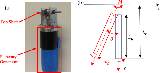
Figure 2. Prototype (a) and schematic (b) of MMR pendulum energy harvester.
Download figure:
Standard image High-resolution imageThe kinetic energy of the engaged system is

where,  is the total rotational inertia of the pendulum system with respect to z-axis;
  and
and  are the rotational inertia of the gearhead and generator with respect to y-axis, respectively.
  is the total length of the pendulum system.
  is the length from the gearhead to the generator (figure 2(b)). One should notice that the kinetic energy of the shaft and the bevel gears has been neglected while deriving equation (2) since they are small compared to that of gearhead and generator.
The total potential energy of the pendulum is

where,  is the mass of the pendulum system.
  is the distance from center of mass of pendulum to central shaft.
  is the gravitational coefficient. Assuming the pendulum has a virtual displacement
  the virtual angular displacement and velocity of the pendulum system are

The back electromotive voltage  of the electrical generator is proportional to the rotation speed
  with a voltage constant ke [25]

The torque of the generator is proportional to the electrical current Ige with a torque constant  [25]
[25]

where  and
and  are the internal and external resistance of the generator. The virtual work done by the generalized force is

One should notice that equation (4) is used when obtained equation (7). The generalized Moment  is
is

Defining the Lagrange function, and substituting
  and
and  into the following Lagrange equation

The equation of motion of the MMR pendulum energy harvester in the engaged scenario is
Now, let

where,  and
and  are defined as the equivalent rotational inertia and equivalent damping of MMR pendulum energy harvester. Here it is assumed the rotational displacement of the pendulum system is small so that
  .
.
In the disengagement scenario, the pendulum and the generator become two decoupled systems. The equation of motion of these two decoupled systems are as follows


One should notice that the mechanical damping in the system has not been considered here. If a linearized mechanical damping is considered, the dynamic equations of the MMR pendulum energy harvester is concluded as follows,when  (the rotation speed of bottom bevel gear
  is equal to the rotation speed of driving gears), the equation of motion of the engaged system is:

when  (the rotation speed of bottom bevel gear
  is larger than the rotation speed of driving gears), the equations of motion becomes two decoupled systems:

where,  and
and  are defined in equation (11);
  is the linearized damping coefficient considering the mechanical damping in the bevel gears and frame;
  is the linearized damping coefficient considering the mechanical damping in the planetary generator. The equation of motion of the non-MMR pendulum energy harvester under harmonic excitation is

where,  is the linearized damping coefficient of the whole system since there is no disengagement in the non-MMR pendulum energy harvester.
4. Simulation results
The equation of motion of the MMR pendulum energy harvester (equations (14) and (15)) are rewritten into non-dimensional form as follows

where, 


 is a non-dimensional time constant.
  is the differential respect to
  For the non-MMR pendulum energy harvester, the non-dimensional equation of motion is

The non-MMR pendulum energy harvester under harmonic excitation in equation (19) is a classical single degree of freedom energy harvesting system and has been investigated in many works [11, 12]. The average output power of the non-MMR pendulum energy harvester is
Taking derivative of  with respect to
  the maximum output power of non-MMR pendulum energy harvester at each frequency is
The corresponding optimal electrical damping is

The non-dimensional equation of motion of MMR pendulum energy harvester is a piece-wise linear system and the average output power is calculated with the following equation

where,  is obtained by solving equations (17) and (18).
Figure 3 shows the non-dimensional maximum output power and corresponding optimal electrical damping for MMR pendulum energy harvester and non-MMR pendulum energy harvester. In figure 3(a), when the equivalent mass  is increased from 0.2 to 0.6, the natural frequency of the non-MMR pendulum energy harvester decreases from 0.91 to 0.79
  Due to the disengagement of one-way clutches in the MMR pendulum energy harvester, the variation of the natural frequency in the MMR pendulum energy harvester is smaller than that of the non-MMR pendulum energy harvester. In addition, the output power of the MMR pendulum energy harvester is higher than that of the non-MMR pendulum energy harvester at high frequencies. Moreover, the bandwidth of MMR pendulum energy harvester is larger than that of non-MMR pendulum energy harvester, especially for large
  When
When  the bandwidth of MMR pendulum energy harvester (which is 0.58 in figure 3(a)) is 48% higher than the bandwidth of non-MMR pendulum energy harvester (which is 0.39 in figure 3(b)). Here, we define the bandwidth as the frequency difference between two points where the power is half of the peak power, as shown in figure 3(a). The corresponding optimal electrical damping in the MMR pendulum energy harvester is larger than the non-MMR pendulum energy harvester at low frequency and smaller at high frequency. The time domain response of MMR pendulum energy harvester is also plotted in figure 4 to illustrate the mechanism of the MMR pendulum energy harvester. The input and output speed relationship of MMR pendulum energy harvester in figure 4(a) clearly shows the engagement and disengagement transition during the pendulum vibration. Due to the disengagement of one-way clutches in the MMR pendulum energy harvester, the output power is always larger than zero, as is seen in figure 4(b).

Figure 3. Non-dimensional plot of maximum output power and corresponding optimal electrical damping for the MMR pendulum energy harvester and non-MMR pendulum energy harvester under different excitation frequency. For the MMR pendulum energy harvester plotted in this figure,  ;
;
 for the non-MMR pendulum energy harvester plotted in this figure,
 .
.
Download figure:
Standard image High-resolution image
Figure 4. Time domain plot of MMR pendulum energy harvester. (a) Input speed and output speed of MMR pendulum energy harvester (b) output power of MMR pendulum energy harvester and non-MMR pendulum energy harvester. For the results plotted in this figure, 
 ;
;

 the electrical damping is chosen as the optimal damping in figure 3(b), which is
  for MMR pendulum energy harvester and
  for non-MMR pendulum energy harvester.
Download figure:
Standard image High-resolution image5. Experimental results
5.1. Experimental setup
The experimental setup for both the MMR pendulum energy harvester and non-MMR pendulum energy harvester is shown in figure 5(a). The setup consists of a Coco-80 vibration data collector, a function generator, a power amplifier, an APS 113 long stroke shaker, an accelerometer and a resistor box. The function generator generates a sinusoidal signal with a specified frequency and amplitude and this signal is used to drive the APS 113 shaker through a power amplifier. The energy harvester is fixed on a u-frame. The u-frame is fixed on the shaker through an adapter. The acceleration of the frame is measured with an accelerometer which is attached on the adapter. The output voltage across an external resistor is measured as an output of the pendulum system. The acceleration and voltage is recorded with Coco-80 vibration data collector. The shaker used here is an APS 113 long stroke shaker (stroke length is 6.5 inches). The prototypes of the MMR pendulum energy harvester and non-MMR pendulum energy harvester used in this experiment are shown in figure 5(b).
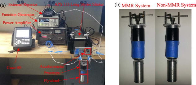
Figure 5. (a) Experiment setup (b) prototypes of MMR pendulum energy harvester and non-MMR pendulum energy harvester with flywheel.
Download figure:
Standard image High-resolution image5.2. Experimental results and discussions
It is known from section 4 that the output power of the MMR pendulum energy harvester is expected to be higher than that of the non-MMR pendulum energy harvester at high frequencies due to disengagement, especially when the equivalent mass in the pendulum system is large. In order to observe the disengagement in the experiment, a flywheel was attached at the end of the generator (figure 5(b)) to increase the equivalent mass since the mechanical damping in the pendulum and gear system is large and nonlinear. The angular displacement of the pendulum was constrained in  during the experiment by tuning the excitation amplitude at different frequencies. Figures 6 and 7 show the measured acceleration and voltage at 3 Hz and 4 Hz. For the non-MMR pendulum energy harvester system, the bevel gear mounted on the top shaft is fixed during pendulum vibration. As a result, the output voltage is periodic. The two bevel gears mounted on the top shaft in the MMR pendulum energy harvester are in rotation and the driving gear switches from one to the other during pendulum vibration. This makes the output voltage irregular since it is impossible to make these two gears have the same engagement performance. As a result, the mechanical damping in the MMR pendulum energy harvester is expected to be larger than that in non-MMR pendulum energy harvester. Nevertheless, the overall performance of the MMR pendulum energy harvester is still better than non-MMR pendulum energy harvester due to the disengagement, as is apparent from the measured voltage in figures 6 and 7.

Figure 6. Measured acceleration of the shaker and output voltage of the MMR pendulum energy harvester and the non-MMR pendulum energy harvester at 3 Hz. The external resistor is 200 Ω. The rotational inertia of the flywheel is four times of the rotational inertia of the generator.
Download figure:
Standard image High-resolution image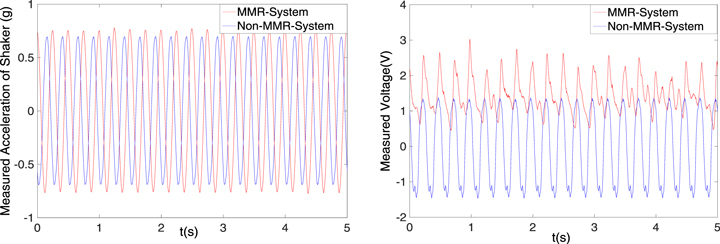
Figure 7. Measured acceleration of the shaker and output voltage of the MMR pendulum energy harvester and non-MMR pendulum energy harvester at 4 Hz. The external resistor is 200 Ω. The rotational inertia of the flywheel is four times of the rotational inertia of the generator.
Download figure:
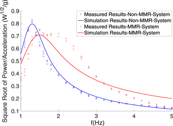
Standard image High-resolution imageFigure 8 compares the performance of the MMR pendulum energy harvester and non-MMR pendulum energy harvester at different frequencies. The x-axis is the excitation frequency while y-axis is the ratio of measured voltage (root mean square value) and acceleration (root mean square value). In figure 8, multiple groups of data were taken for different excitation amplitudes (the measured acceleration is different) at each frequency. The parameters of the prototypes can be found in table 1. Not included are the mechanical damping  and center of mass
  values in equations (14)–(16), these parameters are estimated with the established model in section 3 by minimizing the least squares of the errors between the measured data and simulation results. The simulation results of non-MMR pendulum energy harvester matches well with the experiment results except for those frequencies around peak. The uncertainty is caused by the uncertainty of estimated mechanical damping around resonance. The response of MMR pendulum energy harvester is sensitive to damping around resonance and any small uncertainty in the mechanical damping results in an amplified difference in the response.
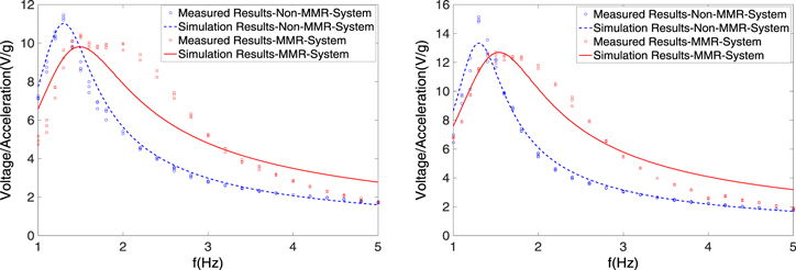
Figure 8. Comparison of the experimental results for the MMR pendulum energy harvester and non-MMR pendulum energy harvester. A fitted curve is also plotted with the model established in section 3. The mechanical damping  and center of mass
  in equations (14)–(16) are calculated by minimizing the least squares of the errors between the measured data and simulation results. The external resistor is 1 MΩ in the left figure and 200 Ω in the right figure.
Download figure:
Standard image High-resolution imageTable 1. Parameters and descriptions of the MMR pendulum energy harvester and non-MMR pendulum energy harvester.
| Symbol | Description | Value |
|---|---|---|

|
Mass of the pendulum system | 0.355 kg |

|
Length of the pendulum system | 0.085 m |

|
Total Length of the pendulum system | 0.11 m |

|
Gear ratio of the bevel gear | 1 |

|
Gear ratio of the gear head | 14 |

|
Rotation inertia of pendulum | 1.5 × 10⁻³ kg m2 |

|
Rotation inertia of generator | 1.3 × 10⁻⁶ kg m2 |

|
Rotation inertia of gear box (input side) | 0.8 × 10⁻⁷ kg m2 |

|
Voltage constant of the generator | 0.053 
|

|
Torque constant of the generator | 0.053 N m A−1 |

|
Internal resistor of the generator | 9.24 Ω |

|
External resistor of the generator | 1 MΩ, 200 Ω |

|
Mass of the flywheel | 0.07 kg |

|
Rotation inertia of flywheel | 5.2 × 10⁻⁶ kg m2 |
Since there are three gears involved during the pendulum vibration for MMR pendulum energy harvester and the driving gear switches from one to another, the simulation results of the MMR pendulum energy harvester do not fit as well as the non-MMR pendulum energy harvester. However the performance of the MMR pendulum energy harvester is still better than the non-MMR pendulum energy harvester at high frequencies and the bandwidth of MMR pendulum energy harvester is larger than that of non-MMR pendulum energy harvester, as expected from the simulation results in section 4. In addition, the natural frequency of the MMR pendulum energy harvester is higher than that of the non-MMR pendulum energy harvester in figure 8, which is consistent with the results in figure 3. For the results plotted in figure 8, the estimated values of mechanical damping and center of mass are cm1 = 0.0186 N m s, cm2 = 0.0019 N m s, cm = 0.1682 N m s, Lc = 0.0725 m. It is found that the estimated mechanical damping in MMR pendulum energy harvester is larger than that in non-MMR pendulum energy harvester, which is in our expectation since the engaged gear switches during pendulum vibration. As a result, the peak response of MMR pendulum energy harvester is smaller than that of non-MMR pendulum energy harvester since the response is sensitive to damping at resonance frequency. The output power of the proposed MMR system and non-MMR system is plotted in figure 9 and the results is consistent with figure 8.
Figure 9. Comparison of the averaged output power for MMR system and non-MMR system. A fitted curve is also plotted with the model established in section 3. The mechanical damping  and center of mass
  in equations (14)–(16) are calculated by minimizing the least squares of the errors between the measured data and simulation results. The external resistor is 200 Ω in this figure.
Download figure:
Standard image High-resolution image
6. Conclusion
In this paper, a pendulum energy harvester with an MMR system was proposed. A pendulum energy harvester without an MMR system was also designed and fabricated for a comparison. The dynamic equation of the MMR pendulum energy harvester is a piecewise linear system due to the engagement and disengagement of one-way clutches used in the gear system. A non-dimensional analysis of these two systems shows that the natural frequency of the MMR pendulum energy harvester is less sensitive to the variation of equivalent mass than the non-MMR pendulum energy harvester. In addition, the output power of the MMR pendulum energy harvester is higher than that of the non-MMR pendulum energy harvester at high frequencies. Moreover, the bandwidth of MMR pendulum energy harvester is larger than that of non-MMR pendulum energy harvester due to the disengagement of one-way clutches in MMR system. Based on the simulation results, the bandwidth of MMR pendulum energy harvester is 48% higher than that of non-MMR pendulum energy harvester when the equivalent inertial is 0.6 times of the pendulum mass, and a higher bandwidth is expected when the equivalent inertial is increased. The disengagement of the MMR system is observed in the experiment and the experimental results verify that both the bandwidth and high frequency output power of MMR pendulum energy harvester are larger than the non-MMR pendulum energy harvester.