

Abstract
Acoustic emission (AE) is a nondestructive evaluation technique that is capable of monitoring the damage evolution of concrete structures in real time. Conventionally, AE sensors are surface mounted on the host structures, however, the AE signals attenuate quickly due to the high attenuation properties of concrete structures. This study conducts a feasibility study of using smart aggregates (SAs), which are a type of embedded piezoceramic transducers, as embedded AE sensors for the health monitoring of concrete structures. A plain concrete beam with two surface mounted AE sensors and two embedded SAs was fabricated in laboratory and loaded under a designed three-point-bending test. The performance of embedded SAs were compared with the traditional surface mounted AE sensors in their ability to detect and evaluate the damage to the concrete structure. The results verified the feasibility of using smart aggregates as embedded AE sensors for monitoring structural damage in concrete. Potentially, the low cost smart aggregates could function as embedded AE sensors, providing great sensitivity and high reliability in applications for the structural health monitoring of concrete structures.
Export citation and abstract BibTeX RIS
1. Introduction
Concrete is the most widely used construction material worldwide. Deterioration of concrete structure results in human injuries and economic losses. Nondestructive evaluation of concrete structures has long been an engineering challenge and a popular research topic. Among various nondestructive evaluation techniques, acoustic emission (AE) has attracted increasing attention, since it is a promising tool for long-term monitoring and evaluation of the damage evolution of concrete structures. An AE sensor detects the stress waves that are generated by the rapid release of energy from a source within a structure undergoing deformation, crack initiation or propagation. The AE signals offer rich damage-related information on the host structure, and so are well-suited for damage detection and assessment of concrete structures (Colombo et al 2003, Ohno and Ohtsu 2010, Zitto et al 2015). Conventionally, AE sensors are mounted on the surface of a structure to capture the AE signals generated from the structure. The coupling between the AE sensors and the structure is achieved using a couplant such as oil or grease. However, it is difficult to maintain stable coupling over time therefore the measurement accuracy decreases in cases of in situ and long-term monitoring of concrete structures. Additionally, the AE signal will be dramatically attenuated as it travels through the concrete due to the high attenuation properties of concrete material, which makes traditional AE techniques inappropriate for health monitoring of a large-scale concrete structure. Moreover, traditional AE sensors cannot be applied to the structures that are difficult to access, for example underground structures.
To avoid the disadvantages of externally mounted AE sensors, the concept of direct embedment of the AE sensors into the structures was proposed. The method of sensor embedment provides excellent coupling between AE sensors and host materials, eliminating the measurement bias due to decoupling between the AE sensor and the host structure over time. These sensors can be installed in locations where accessibility is a serious problem after the structure is built and in service. Over the last few years, some advances have been achieved in developing embedded piezoelectric sensors, such as AE sensors for the health monitoring of concrete structures. In 2010, Qin et al (Qin et al 2010) introduced a novel embedded AE sensor based on 0–3 (the first and second digits represent the dimension of the piezoelectric particles and the matrix, respectively) cement-based piezoelectric composites. The sensor was fabricated by compacting mixed cement-piezoelectric powder into a thin plate patch and higher sensitivity was achieved through a four point bending test of a concrete beam. Similarly, in 2011, Lu et al (Lu et al 2011) devised a 0–3 cement-based piezoelectric composite and it was employed as an embedded AE sensor in monitoring the damage process of reinforced concrete frames subjected to seismic loading. In 2014, however, in addition to the 0–3 type, Qin et al (Qin et al 2014) investigated the practicality of 1–3 type cement-based piezoelectric composites as embedded AE sensors. The characteristic of the broadband frequency response of the sensors was validated through concrete hydration and thermal cracking experiments. However, the fabrication procedures of these piezoelectric composite AE sensors are complicated, requiring a specialized mixing ratio. Although extensive work has been done in developing the embedded AE sensors, a desirable embedded AE sensor has not yet been discovered.
Smart aggregate (SA), as a piezoceramic based embeddable transducer, is made of a thin PZT (lead zirconate titanate) patch that is protected by a concrete or marble case (Gu et al 2006). SAs can act as both actuators that generate high-frequency stress waves and sensors that receive the waves. Most applications of SAs are focussed on a transmitter–receiver configuration for structural health monitoring of concrete structures, such as early age concrete characterization (Song et al 2008, Kong et al 2013), damage detection of concrete columns (Moslehy et al 2010) and crack propagation monitoring for reinforced concrete beam structures (Dumoulin et al 2015). The suitability of SAs as embedded AE sensors has not been investigated. Compared to the embedded cement-based piezoelectric composites, SAs are low cost, without the need for complicated fabrication procedures as in piezoelectric composites.
In this paper, we report on a feasibility study of using SAs as embedded AE sensors for the structural health monitoring of concrete structures. The performance of SAs was compared with traditional surface mounted AE sensors in their ability to detect and evaluate the damage of concrete structures. The frequency response of traditional embedded AE sensors is calibrated using the Hsu–Nielsen method. A concrete beam specimen with two embedded SAs and two surface mounted AE sensors was fabricated in the laboratory. In the experimental study, the concrete beam specimen was loaded under a three-point-bending test. The crack evolution during the loading test was monitored by using the two types of sensors and the experimental results were compared.
2. Embedded PZT-based SAs
PZT is a piezoelectric material which can function as both a sensor and an actuator. As a sensor, the PZT produces a voltage when subjected to stress or strain. Conversely, as an actuator, the PZT generates a stress wave when an electric field is applied. The SA was fabricated by sandwiching a PZT patch between two marble blocks with epoxy, as illustrated in figure 1. The dimensions of the PZT patch are 15 mm × 15 mm and thickness 0.3 mm. The SA had a diameter of 25 mm and a height of 20 mm. The SA was interfaced to the instruments via a Bayonet Neill–Concelman connector. The properties of the PZT are listed in table 1. The marble protection of the SA served two purposes. First, the structure protects the fragile PZT patch from external disturbance or water damage. Second, the structure maximizes the energy transmission between the PZT patch and the test specimen, which is also known as acoustic impedance matching (Dumoulin et al 2015).

Figure 1. Illustration and photo of the SA.
Download figure:
Standard image High-resolution imageTable 1. Typical properties of the PZT patch.
| Property (unit) | Magnitude |
|---|---|
| Young's Modulus (GPa) | 46 |
| Density (103 kg m−3) | 7.45 |
 (pC N−1) (pC N−1) |
−186 |
 (pC N−1) (pC N−1) |
670 |
 (pC N−1) (pC N−1) |
660 |
Since SAs have similar size to aggregates in concrete mix, they can provide excellent embeddability and compatibility when used as an embeddable sensor. The nondestructive evaluation of concrete structures will be enhanced when the SAs are incorporated within the structure. In such a case the structure becomes an integrated smart system that can perform both AE sensing and active-sensing based health monitoring (i.e. a transmitter–receiver configuration and impedance approach) of the concrete structures.
3. Experimental setup
To study the suitability of the SAs as embedded AE sensors, a plain concrete beam was constructed with pre-embedded SAs in the laboratory. The concrete had a cross-section of 100 mm × 100 mm and a length of 400 mm, as shown in figure 2. The expected compressive strength of the concrete is 27 MPa after 28 days' curing. Two SAs were used, located at the left and right quarter points of the longitudinal axis of the concrete beam, respectively, as shown in figure 2. For comparison, two AE sensors were mounted on the front surface of the concrete beam, which shared the same cross-sections with the SAs. The AE sensors used were wideband sensors (Physical Acoustic Corporation, PAC) which have very good frequency response over the range of 100 kHz to 900 kHz. The AE sensors were coupled to the concrete surface using brown grease and tightly attached using hot glue. The left-hand sides of the SA and AE sensors were labeled as SA-1 and AE-1, and the right-hand sides of the two sensorss were labeled as SA-2 and AE-2.

Figure 2. Dimensions of the concrete beam with embedded SAs and surface mounted AE sensors.
Download figure:
Standard image High-resolution imageA three-point-bending test was adopted to induce cracking damage to the concrete specimen. The support conditions are shown in figure 2. The upper load bar was centered between the two supports. The distance between the two supports was 300 mm. Figure 3 shows the three-point-bending test setup using an INSTRON 5969 testing machine with 50 kN capacity. The testing machine was set at displacement control mode at a rate of 0.05 mm min−1. The load–displacement relationship at the mid-span of the beam was automatically registered by the testing machine. The machine automatically stopped after a drop of 40% in the maximum load to ensure safe operation. The AE data acquisition system used was the Micro-II Digital AE System from PAC. Both the SAs and the AE sensors were connected to pre-amplifiers before feeding to the AE system. The sampling frequency for the recording AE waveforms was 5 MHz. The threshold level was set at 40 dB, which was calibrated using a pencil lead break test. The threshold was sensitive enough to capture significant AE signals while rejecting noise from the testing environment. The signals were amplified with 40 dB gain by the pre-amplifiers. The AE waveforms and parameters, such as hits, amplitude, counts and energy were recorded on the computer, and could be exported as text files for further processing.
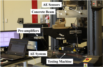
Figure 3. AE system setup and three-point-bending test.
Download figure:
Standard image High-resolution imagePrior to the three-point-bending test, the frequency response of the SAs was examined using the Hsu–Nielsen method. The Hsu–Nielsen source was generated by breaking a 0.5 mm pencil lead against the concrete specimen (E976, A 2005). The pencil lead break source is a flat and broadband acoustic source, which is very suitable for frequency response calibration of AE sensors. The pencil lead break locations were along the longitudinal center line on the top surface, from left end to the right end with a spacing of 50 mm. There were nine locations in total and the test was repeated three times.
4. Results and discussion
4.1. Frequency response of SA
The amplitude of the sensors along the center line on the top surface at different pencil lead break locations is plotted in figure 4. As can be seen, all of the amplitudes reach around 80 dB, which is a typical value for a pencil lead break acoustic source. From a sensitivity point of view, the SAs share the same sensitivity as the surface mounted traditional AE sensors. Normally, the sensitivity of the SA is directional, which means that the SA receives stronger signals when a wave hits the SA along its axial direction and weaker signals when a wave is received from the radial direction of the SA. Note that, at a location 100 mm for SA-1 and 300 mm for SA-2, these pencil lead break locations are along the radial planes of SA-1 and SA-2 respectively, as shown in figure 2. At these locations, the AE sources reach the SAs from the radial direction, which should have the lowest sensitivity since the PZT patch is under compressive mode. From figure 4, no significant signal attenuation along the radial direction can be found. This experimental verification shows that SAs can be good candidates for AE sensors. The directionality of the SA is negligible in our study.

Figure 4. Amplitude plot of the sensors at different locations.
Download figure:
Standard image High-resolution imageFigure 5 shows the response of the SAs and the traditional AE sensors due to pencil lead break tests, including time domain and frequency domain. It is clearly shown in the figures that the frequency response of SAs tend to show higher magnitude in the low frequency band, which ranges from 20 kHz to about 200 kHz. For the traditional AE sensors, their frequency response tends to peak in frequency bands from 20 kHz to 50 kHz and around 100 kHz.

Figure 5. Frequency response of the SAs and the traditional AE sensors due to pencil lead break.
Download figure:
Standard image High-resolution image4.2. Results of the concrete beam test
Figure 6 shows the load curve and the AE activity evolution. When the load was low, say less than 2 kN, very limited AE events were detected by both SAs and AE sensors. As the applied load increased, the concrete beam began to be damaged in the form of micro-cracking within the structure. The progression of the micro-cracking damage of the concrete beam was indicated by a constant evolution of AE hits before the ultimate failure of the concrete beam. As the concrete beam failed, marked by a sudden drop of load capacity and macro-cracking on the surface, a sudden increase in the AE hits was detected by all the sensors, as shown in figure 6. As can be seen, the developing trend of the AE events recorded by these four sensors follow the same pattern. All sensors except AE-1, recorded about 1000 AE events. The reason that AE-1 registered more AE events maybe related to a tighter coupling condition during the coupling process as compared to the AE-2 sensor.

Figure 6. Load curve and accumulated AE hits plot.
Download figure:
Standard image High-resolution imageAE parameters, such as amplitude, counts, energy, duration and rise time in time domain and peak frequency and average frequency in frequency domain, provide useful information for the source identification and determination of the severity of damage of the structure. During the process of the deterioration of the concrete structure, types of cracks (micro-cracks and macro-cracks) are closely related to the AE amplitude distribution. The micro-cracking usually generates a large amount of events of small amplitude, while macro-cracking generates fewer events but of larger amplitude. The amplitude plots of AE events recorded by these four sensors are shown in figure 7. As can be seen, most of the events show low amplitude across the time frame of the test, which are related to the initiation and propagation of micro-cracks. When the concrete approaches the ultimate failure state (around 720 s), strong and dense events were detected, which were generated from the macro-cracking of the concrete specimen. It is evident that the amplitude plots of SAs share a similar trend with that of AE sensors. Therefore, the feasibility of SAs as embedded AE sensors were further validated. The counts plots are shown in figure 8, which also present the same indication as amplitude plots. There are strong signals at the moment when the concrete totally failed. All other AE parameters in the time domain also showed the same indication since these parameters are closely correlated to each other.

Figure 7. Amplitude plots of AE signals from the four AE sensors.
Download figure:
Standard image High-resolution image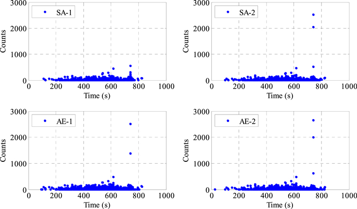
Figure 8. Count plots of AE signals from the four AE sensors.
Download figure:
Standard image High-resolution image
From a sensitivity point of view, the embedded SAs did not show superiority over the conventional surface mounted AE sensors since the dimensions of the concrete sample were quite small. The location of the SAs and AE sensors are very close to each other in this case. It should be noted that the high-frequency acoustic emission waves are rapidly attenuated in concrete structures. The attenuation rate of the AE wave propagation in concrete structures can go up to 29 dB m−1 (Farhidzadeh et al 2012). The attenuation of AE signals will significantly affect the value of AE signal parameters such as amplitude, duration and energy, which are the most important parameters in evaluating the damage severity of the structure. The application of conventional surface mounted AE sensors usually requires a stringent sensor placement scheme for each individual tested structure to ensure the adequate coverage of the structure under test (Golaski et al 2002). However, as a type of embedded AE sensor, the SAs can be easily be embedded at the location of interest that is more prone to be damaged. In this way the SAs are more sensitive to detect the damage of a structure, and more information will be registered in evaluating the integrity of the tested structures.
Another important issue that needs pointing out is the effect of temperature on the AE properties of the structure since such an issue will be faced in certain applications. This is not an issue in most environments, but may be important in very hot or very cold climates (Ziehl and Pollock 2012), and in some engineering structures affected by high temperatures such as in a gas explosion, nuclear reactor shielding layers, tunnels, mine fires, etc (Geng et al 2016). In low or in high temperature, the properties of the concrete structure become complicated, and the physical and mechanical properties of the concrete will change with temperature, as do the AE characteristics of the structure. Geng et al detailed the property changes of concrete structures at different temperatures (Geng et al 2016). According to their findings on the effects of temperature on the strength and real-time acoustic emission signals of concrete, the number of AE events were fewer at high temperatures than that at lower temperatures. The concrete at low temperatures tends to be more compact and has higher bonding strength, and thus will release more energy in the course of loading. As a result, more AE events will be generated. By contrast, when the concrete is treated in high temperatures, the concrete becomes loose. Under the effect of loading, the concrete will release less energy and there will be fewer AE events. The properties of the AE waveforms and the propagation of the waves will also be modified due to the physical and mechanical properties changes in the concrete. These properties include the AE wave velocity, amplitude, resonant frequency and so forth. In general, the effect of temperature on the AE characteristics of concrete structures is a complicated problem and requires in-depth study.
5. Conclusions
In the present study, the feasibility of using SAs as embedded AE sensors for damage characterization of concrete structures has been experimentally investigated. A pre-experimental verification using a standard pencil lead break test was conducted to compare the frequency response of SAs and traditional AE sensors. The results showed that the SAs tend to be more sensitive in the low frequency band, ranging from 20 kHz to 200 kHz. Further, in order to study the functionality of SAs being used as AE sensors in concrete health monitoring, a plain concrete beam with two embedded SAs and two surface mounted AE sensors was investigated under a three-point-bending test. The AE parameters that were used to describe the damage progression of the tested concrete structures, such as hits, amplitude and counts, from both the SAs and traditional AE sensors showed similar characteristics. The results confirmed the feasibility of using SAs as embedded AE sensors for the structural health monitoring of concrete structures. The use of SAs as embedded AE sensors possesses several advantages. Firstly, the structure and the fabrication process of SAs are simple and low cost. Secondly, the embedded SAs are capable of serving in situ and long-term monitoring of concrete structures, without addition manual check for coupling between the sensor and the structure. Finally, the SAs can be pre-embedded into a structure, which makes them more suitable for monitoring of large-scale structures and structures with accessibility issues. While the results from laboratory tests are encouraging, the efficacy of the SAs as embedded AE sensors has never been tested for practical applications. In the future, SAs will be deployed in large-scale concrete structures, and a further feasibility study on practical applications of using SAs as embedded AE sensors will be conducted.
Acknowledgments
This research reported in this paper was partially supported by the Major State Basic Research Development Program of China (973 Program, No. 2015CB057704) and the China Scholarship Council (No. 201306060086).