
Abstract
Currently, flapping wing unmanned aerial vehicles (a.k.a., ornithopters or robotic birds) sustain very short duration flight due to limited on-board energy storage capacity. Therefore, energy harvesting elements, such as flexible solar cells, need to be used as materials in critical components, such as wing structures, to increase operational performance. In this paper, we describe a layered fabrication method that was developed for realizing multifunctional composite wings for a unique robotic bird we developed, known as Robo Raven, by creating compliant wing structure from flexible solar cells. The deformed wing shape and aerodynamic lift/thrust loads were characterized throughout the flapping cycle to understand wing mechanics. A multifunctional performance analysis was developed to understand how integration of solar cells into the wings influences flight performance under two different operating conditions: (1) directly powering wings to increase operation time, and (2) recharging batteries to eliminate need for external charging sources. The experimental data is then used in the analysis to identify a performance index for assessing benefits of multifunctional compliant wing structures. The resulting platform, Robo Raven III, was the first demonstration of a robotic bird that flew using energy harvested from solar cells. We developed three different versions of the wing design to validate the multifunctional performance analysis. It was also determined that residual thrust correlated to shear deformation of the wing induced by torsional twist, while biaxial strain related to change in aerodynamic shape correlated to lift. It was also found that shear deformation of the solar cells induced changes in power output directly correlating to thrust generation associated with torsional deformation. Thus, it was determined that multifunctional solar cell wings may be capable of three functions: (1) lightweight and flexible structure to generate aerodynamic forces, (2) energy harvesting to extend operational time and autonomy, and (3) sensing of an aerodynamic force associated with wing deformation.
Export citation and abstract BibTeX RIS
1. Introduction
Unmanned aerial vehicles (UAVs) are emerging as an important tool in a wide variety of defense and civilian applications [1–3]. Flapping wing UAVs have the potential to combine the positive aspects of both fixed-wing and rotary flight, while eliminating many of the negative aspects. Inspiration for flapping has been derived from bats, insects, and birds, and many different platforms have been constructed, characterized and modeled [2–22]. For example, the robotic birds, Small Bird and Big Bird, constructed at the University of Maryland, as well as the ornithopter constructed at the University of Delaware [22–25]. Though the size and chassis of each of these UAVs may differ, the wings were all similar in nature. They were constructed using stiff lightweight rods as structural materials and a thin Mylar-based film as the wing surface.
As a part of previous work, we have developed a highly maneuverable robotic bird named Robo Raven [26, 27]. Robotic birds are vehicles that rely on flapping wings and their deformation to generate the aerodynamic forces necessary for flight. The size of these vehicles are comparable to the size of an actual bird found in nature. This platform features independently controlled programmable wings. In robotic birds such as Robo Raven, flight endurance is one of the primary concerns. To perform missions in remote regions, the UAV cannot charge batteries using electrical outlets. A possible way to overcome this challenge would be to charge batteries using on-board solar cells. Since Robo Raven has a large wing area, solar cells can be integrated into the wings. The resulting compliant wing structure with integrated solar cells can be considered both multifunctional and smart because it not only provides lift and thrust, but also acts as a method of harvesting energy and sensing changes in deformation caused by aerodynamic loading, which can be used to determine changes in the flapping profile to improve flight control. This combination allows for increased flight time while decreasing the payload contribution of a large power source, thus potentially allowing for either: (1) size reduction with the same performance capability, or (2) an increase in overall payload capacity. It also introduces new capabilities for control schemes through new sensing capabilities. Successful development of multifunctional compliant wing structures through the integration of multiple functions can be expanded to other aspects of all UAVs, including fixed wing and rotary craft.
Multi-functional structures combine multiple functional requirements into a single structural component to create better efficiency in the overall design [28, 29]. For example, a micro air vehicle (MAV) constructed with MEMS technology has a membrane made of a PVDF skin, allowing it to act as a real time load sensor to directly analyze flight performance [13, 14]. Ma et al developed another MEMS-based insect-inspired flapping wing platform known as RoboBee uses artificial muscles to achieve novel controlled flight dynamics [30]. Thomas et al described the combination of structure and battery in the design of an electric-propelled UAV as an example of a multi-functional material system [29, 31]. More recently at the University of Maryland, elastomeric strain gauges were placed on the wings of a flapping wing MAV [32]. These sensors captured deformations caused by flapping. The outputs from these sensors were directly correlated to thrust production which essentially made the wing into a skin-like structure. For remote applications, endurance will be an important performance metric as evidenced through flight time for UAVs. Flight time is directly related to the energy supplied by the battery, the weight of each component of the UAV, and aerodynamic parameters. The ability to harvest energy and sense changes in wing deformation increases endurance and improves system efficiency, which directly impacts all areas of the flight envelope.
Integrating solar cells in the wings present the following three challenges. First, a new manufacturing process is needed to integrate solar cells into wings without substantially increasing weight. Second, we need to ensure that wings with integrated solar cells maintain the appropriate deformation during the flapping cycle to ensure production of adequate aerodynamic lift and thrust. Finally, we need to make sure the modified version of Robo Raven with multifunctional wings produces enough thrust and lift to compensate for the heavier wings and enable flight.
In this paper, we describe a new layered fabrication method for integrating commercial off-the-shelf solar cells into wings for a new solar-powered FWAV (flapping wing aerial vehicle): Robo Raven III. Different wing designs were tested to observe how adding different quantities of solar cells affects flight performance through wing deformation, and how this leads to changes in power output that can be measured for potential onboard sensing and control. A new multifunctional performance analysis is also developed to quantify the effects of solar cell integration on recharge time and flight time to determine trade-offs from the multifunctional effects of solar cell integration to be considered by examining the impact of lift and thrust on power requirements versus the gains from recharging by harvesting solar energy.
2. Design and layered manufacturing process for compliant multifunctional wings
2.1. Design of compliant multifunctional wing
Multifunctional wings were created for Robo Raven III (figure 1). The design of the multifunctional wing, also seen in figure 1, was adapted from a design we used previously for successfully realizing flapping wing UAVs, which has been shown to be effective in generating lift and thrust forces across a variety of applications and size scales [23–26]. The parameters of the wing are as follows: S is the semi-span, C is the chord, and  are the diameters of carbon fiber stiffening rods. Table 1 presents values of the wing parameter used in the design reported in this paper. The wing membrane is a 0.001'' thick film of biaxially-oriented polyethylene terephthalate (Mylar) which provides flexibility and toughness while remaining lightweight. Table 2 lists the properties of the base Robo Raven platform with batteries.
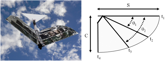
Figure 1. (left) Robo Raven III, the first solar powered robotic bird using multifunctional wings, and (right) parameters for the multifunctional wing design: S is the semi-span, C is the chord, and  are the diameters of carbon fiber stiffening rods. Youtube video: https://www.youtube.com/watch?v=t1_mPe8Y0V4.
Download figure:
Standard image High-resolution imageTable 1. Parameters for multifunctional wing design.
| Parameter | Value | Units |
|---|---|---|
| S | 605.8 | mm |
| C | 362.0 | mm |
| t1 | 3.18 | mm |
| t2 | 1.63 | mm |
| t3 | 1.63 | mm |
| t4 | 1.63 | mm |
| θ1 | 0.358 | Rad |
| θ2 | 0.750 | Rad |
Table 2. Properties of Robo Raven. Youtube video: https://www.youtube.com/watch?v=mjOWpwbnmTw.
| Parameter | Robo Raven | Unit |
|---|---|---|
| Total mass | 0.29 | kg |
| Length | 0.554 | m |
| Wingspan | 1.168 | m |
| Average chord | 0.248 | m |
| Aspect ratio | 2.01 | |
| Flight speed | 6.7 | m s−1 |
2.2. Multifunctional wing fabrication
To produce appropriate aerodynamic lift and thrust forces, many ornithopters rely on large deformations using compliant wings at lower flapping frequencies to achieve airfoil shapes [26]. The basic compliant wing structure weighs 16.8 g with a total area of 1420 cm2. To maintain compliance when creating a multifunctional wing with a similar structure, Powerfilm's© MPT6-75 flexible solar cell modules were chosen. These flexible 7.3 × 11.4 cm solar cell modules are reported by the manufacturer to produce 50 mA of current at 6 V at 100% sunlight flux, which represents their maximum power point. However, the bending stiffness and mass of the solar cells as packaged and was much higher than the Mylar, and therefore would not allow the wing to deform enough to maintain flight. Therefore, modifications had to be made to the solar cells to reduce the mass and bending stiffness to be more compatible with the Mylar. By heating and peeling off the protective encapsulation on the solar cells, the bending stiffness of the solar cells and mass was substantially reduced. Then, solar modules were glued and soldered together in parallel to produce more current. Creating the multifunctional wings from the de-encapsulated solar cells modules involved a layered manufacturing process (figure 2), and the completed multifunctional wing structure integrated into Robo Raven III can be seen in figure 3.
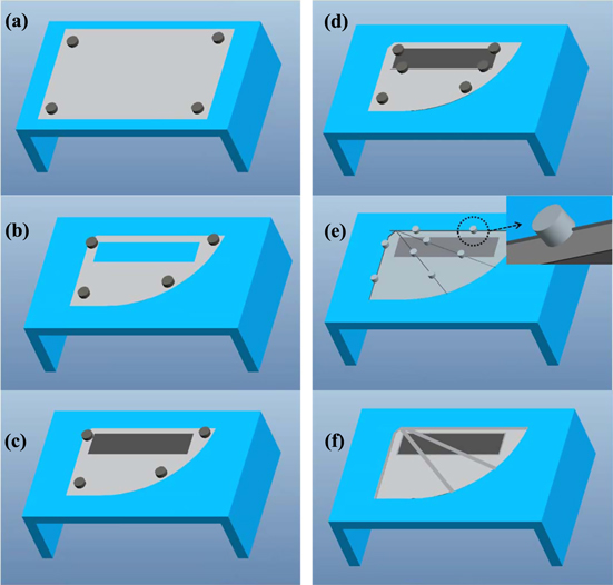
Figure 2. Layered manufacturing process for multifunctional solar cells wings (bottom side of wing is shown).
Download figure:
Standard image High-resolution image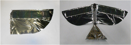
Figure 3. (Left) Assembled multifunctional wing with 6 solar cell modules, (right) multifunctional wings integrated into Robo Raven III.
Download figure:
Standard image High-resolution imageTo fabricate the wing, a layered manufacturing process was developed to provide precise control over the location of each element of the wing (figure 2). The layered manufacturing process consisted of the following steps:
- (a)A sheet of Mylar is secured to a work table with the use of magnets.
- (b)The wing shape including the hole for the solar modules is cut from the secured sheet of Mylar.
- (c)The solar modules are applied to the wing.
- (d)A Mylar frame is adhered around the solar modules that holds the solar cells in place.
- (e)The spars are held in place using magnetic holders with notches while they are adhered to the wing.
Once Robo Raven III was completed, a flight test was conducted and it was determined that the platform could achieve flight. The first version of Robo Raven III used 6 solar cell modules in each wing to generate 300 mA at 6 V, so a second row of solar cells consisting of 5 modules were used to replace as much of the original wing material as possible (figure 4). This version of Robo Raven III was also flight tested, and it was determined that the new wing design was incapable of continuous flight for more than 10 s due to increase in mass and decrease in thrust and lift force generation. Based on our previous experience, additional compliance at the trailing edge of the wing can compensate for the increase in stiffness over the area of the wing when solar modules are integrated, so the wing was redesigned accordingly. The modified wing design compared to the original wing design can also be seen in figure 4. There are three main differences between the new design and the previous. The first two involve extending carbon fiber tubes in the inside part of the wings to permit increase in wing area and compliance of the wing at the trailing edge. The final modification involved changing the shape of the Mylar skin into a 'teardrop'. It was determined that the modified wing design was capable of restoring flight capability to Robo Raven III (see https://www.youtube.com/watch?v=a8x8P5F3qTI).
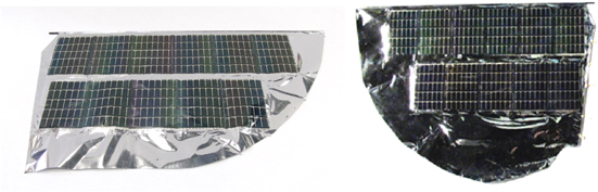
Figure 4. (Left) original Robo Raven III wing design with 11 solar cell modules, and (right) the modified wing design.
Download figure:
Standard image High-resolution image2.3. Integrating multifunctional wings into Robo Raven for energy harvesting
Robo Raven uses a two-cell lithium polymer battery rated at 7.4 V and 370 mAh. To maintain the balance of the battery cells when charging with the multifunctional wings, a charging circuit was design as seen in figure 5. Each module produces 50 mA at 6 V at 100% sunlight flux with the voltage from each wing depicted in figure 5 as V1 and V2. A zener diode with a breakdown voltage of 4.3 V is used to regulate the voltage so it does not exceed the maximum of 4.2 V for each cell. The resistor in the circuit was chosen to achieve the appropriate voltage drop from the modules based on their current, reducing the power generation by 25%.
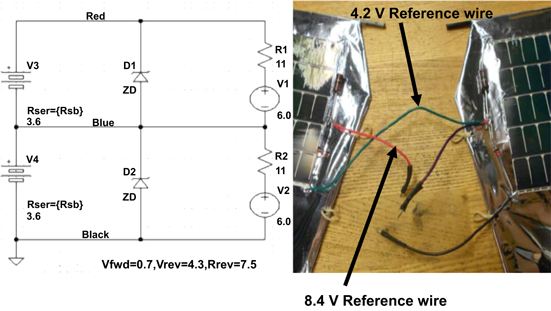
Figure 5. (Left) Schematic of battery charging circuit used for multifunctional wing structures, and (right) the actual wiring of the solar cells for the circuit.
Download figure:
Standard image High-resolution imageFor direct powering of the servomotors, the solar cells can be directly connected to the servomotors instead of the battery. This is possible since servos can operate at up to 7.2 V and the solar cell output has been measured up to 7.8 V. This would optimize performance of the solar cells for powering the UAV in series with the battery pack, as opposed to the 25% reduction in power experienced when utilizing the recharge circuit for the battery. This has an additional benefit of prolonging the life of the battery by allowing the solar cells to assist the battery in powering the UAV, thereby reducing the current draw on the battery and extending the discharge time.
3. Experimental characterization of wing mechanics
3.1. Measurement of lift and residual thrust forces
Since existing computational models are inadequate for accurately predicting aerodynamic loads acting on compliant flapping wings, direct measurement of these loads during the flapping cycle was selected as the method for gaining insight into the effects of wing design parameters on the wing mechanics. For this study, we used a new test stand we developed with a 6 DOF ATI Mini40 load cell mounted on a wood and Delrin frame for measuring aerodynamic lift and thrust loads simultaneously, as well as the moments generated (figure 6). The test stand also allowed the UAV to be set to any angle of attack from 0° to 20°, which was the angle of the bird body relative to the wind direction. To simulate the actual flight conditions, the test stand is placed at the end of a wind tunnel operating at 6 m s−1, which is near the actual flight speed.
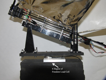
Figure 6. Test stand used in wind tunnel to characterize aerodynamic lift and thrust loads on the compliant multifunctional wings.
Download figure:
Standard image High-resolution imageThe wings were testing at a flapping frequency of 4 Hz and a range of 60°. The wings flapped symmetrically orthogonal to the body of the UAV. Time resolved load profiles for wings with and without solar cells can be seen in figure 7 for Robo Raven. These thrust and lift profiles are consistent with previous measurements and models of flapping wings where the lift produces a sinusoidal profile consistent with aerodynamic drag while the residual thrust exhibits a double peak consistent with a 'blowback' effect from the rear of the wing during the flapping cycle [33]. As a result, the peaks appear 180° out-of-phase when they overlap on the time-resolved plot.

Figure 7. Time resolved load cell results for all four wing designs: (top left) regular, (top right) 6 module, (bottom left) 11 module, (bottom right) modified 11 module.
Download figure:
Standard image High-resolution imageComparing these profiles for each wing design, it can be seen that there is a slight change in performance caused by the addition of solar cells on the wings. Because the solar cells stiffen the wings and reduce compliance in sections of the wing structure, it was predicted that the solar cell wings would underperform the regular wings. However, from the profiles it seems that the 6 module wings actually have slightly larger values for lift compared to the regular wings. For the 11 module wings, the values for thrust decreased significantly compared to the original wings with only a slight increase in lift, which was consistent with the observed loss of flight capability. The modified wing design had an increase in lift force generation compared to the original wings, consistent with the observed restoration of flight capability. The average values of lift and residual thrust load for each trial can be seen in table 3.
Table 3. Lift and residual thrust loads generated by each wing design.
| Robo Raven | 12 module Robo Raven III | 22 module Robo Raven III | Modified 22 Robo Raven III | |||||
|---|---|---|---|---|---|---|---|---|
| Residual thrust (g) | Lift (g) | Residual thrust (g) | Lift (g) | Residual thrust (g) | Lift (g) | Residual thrust (g) | Lift (g) | |
| Trial 1 | 111 | 218 | 105 | 201 | 70.6 | 240 | 77.4 | 247 |
| Trial 2 | 104 | 220 | 98 | 219 | 75.2 | 242 | 101 | 229 |
| Trial 3 | 109 | 221 | 98 | 218 | 91.9 | 237 | 74.8 | 268 |
| Average | 108 | 220 | 100 | 212 | 79.2 | 240 | 84.5 | 248 |
| Std. Dev. | 3.36 | 1.79 | 3.86 | 10.1 | 11.2 | 2.53 | 14.7 | 19.5 |
In a wind tunnel, a residual thrust value of 0 g would correlate to steady-state flight conditions. However, our low speed wind tunnel has a maximum velocity of ∼6 m s−1, while the actual flight velocity for Robo Raven is 6.7 m s−1. Since this meant the aerodynamic force would be approximately 25% greater during flight, a scaling factor of 1.4 X was determined using this value combined with a measured maximum payload of 40 g for Robo Raven. Thus, this scaling factor made it possible to predict the corresponding payload capacity of Robo Raven from the wind tunnel data. The corresponding results, seen in table 4, clearly explain why the original 22 module UAV did not fly given the predicted payload of −4 g, which was recovered to 21 g with the modified wing design.
Table 4. Weight and payload characteristics for each UAV design.
| Robo Raven | 12 module Robo Raven III | 22 module Robo Raven III | Modified 22 module Robo Raven III | |
|---|---|---|---|---|
| Weight of UAV (g) | 290 | 317 | 331 | 346 |
| Force magnitude (g) | 234 | 235 | 232 | 260.1 |
| Total flight weight (g) | 330 | 332 | 327 | 367 |
| Payload (g) | 40 | 15 | −4 | 21 |
3.2. 3D digital image correlation (DIC) characterization of wing shape
Previously, Stanford et al used 3D DIC to study wing deformations in fixed membrane wings for MAVs to optimize their design for aerodynamic forces [34]. Therefore, 3D DIC was used to study the effects of deformation on the different multifunctional wing designs by quantifying differences in shapes and strain and relating it to the aerodynamic loads generated during flapping. For our 3D DIC investigation, two Flea3 FL3-FW-03S1M cameras were used to acquire stereoscopic high speed images at 80 HZ while the wings were flapping at 4 Hz. Speckle patterns were applied to the surface of the wings, and the software package VIC-3D (Correlated Solutions, Inc.) was used to obtain deformation measurements at 20 different angles during a single flapping cycle.
Representative DIC data associated with wing shape be seen in figure 8, which was obtained by taking the out-of-plane displacement (W) in the z-direction normal to the wing while it is in a horizontal position while flapping downwards. For these measurements, the x-axis and corresponding U displacements were chosen to run along the leading spar of the wings, while the y-axis and V displacements runs along the body of the UAV. At the horizontal position, wings are generating the most aerodynamic lift and exhibit the greatest deformation. It is clear that the regular wing has greater deformation towards the trailing edge of the wing than the 6 module wing or the 11 module wing, where the deformations are more indicative of bending on the leading edge. These larger deformations are intuitive since the wings are not stiffened by the addition of solar cells.

Figure 8. Comparison of out-of-plane displacement (W) for each wing at the horizontal position while flapping downward, which was found to be most representative of the relative deformations between the wing designs for the 20 different wing positions that were measured during a single flapping cycle. (Top left) regular, (top right) 6 module, (bottom left) 11 module, (bottom right) modified 11 module. Dashed lines indicate approximate location of the modules.
Download figure:
Standard image High-resolution imageA comparison was also made between the four wings and the time-resolved resolved thrust and aerodynamic lift loads versus the average shear strain and biaxial strain respectively of the entire surface of the wing throughout the flapping cycle (figures 9 and 10). The aerodynamic lift and thrust correlate strongly with the biaxial strain and shear deformation from the DIC results. The correlation between the lift and thrust forces to the biaxial and shear strains have been measured using the correlation coefficient, and are shown in table 5. Since we are interested in the change in biaxial strain, the mean strain was subtracted from the strain observed throughout the flapping cycle to compare the differences. The correlation of lift with biaxial strain is consistent with the aerodynamic shape change responsible for lift that is caused by out-of-plane bending deformation and induces in-plane biaxial strain, while the correlation of thrust to shear strain is consistent with the out-of-plane torsional deformation responsible for thrust that induces in-plane shear strain.

Figure 9. Comparison of time resolved residual thrust and shear strain: (top left) regular, (top right) 6 module, (bottom left) 11 module, (bottom right) modified 11 module.
Download figure:
Standard image High-resolution image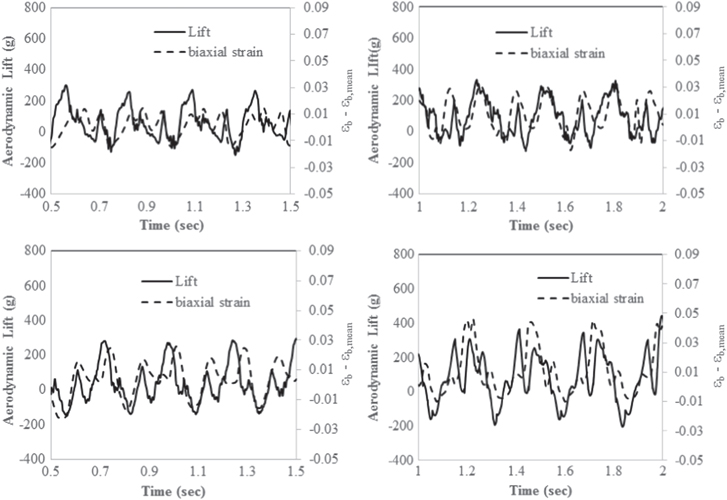
Figure 10. Comparison of time resolved aerodynamic lift and biaxial strain relative to mean biaxial strain for the entire wing: (top left) regular, (top right) 6 module, (bottom left) 11 module, (bottom right) modified 11 module.
Download figure:
Standard image High-resolution imageTable 5. Correlation coefficient of thrust and shear strain and correlation coefficient of lift and biaxial strain for each wing design.
| Robo Raven | 12 module Robo Raven III | 22 module Robo Raven III | Modified 22 module Robo Raven III | |
|---|---|---|---|---|
| Thrust/shear strain correlation coefficient | 0.45 | 0.43 | 0.65 | 0.66 |
| Lift/biaxial strain correlation coefficient | 0.56 | 0.35 | 0.58 | 0.77 |
As mentioned earlier, it is clear that the integration of solar cells has an effect on the wing shape during the flapping cycle due to the increased stiffness of the solar cell material relative to Mylar. This in turn reduces the amount of thrust and lift as the solar cells are integrated into the regular wing design. However, by increasing the wing area in the modified 11 module wing design, residual thrust and lift could be recovered, although greater deformation was also observed that could influence performance. The 17% increase in wing area provided an additional 7% of thrust force and 4% of lift force.
As the majority of the wing becomes covered in solar cells, the deformation of the wing decreases. By observing the time resolved results from the 6 module and 11 module wings, it is clear that the shear strain slightly decreases as solar cells are added. Where the 6 module wing achieved a strain of 2% the 11 module wing remains under 2%. By increasing the wing size and allowing for more deformation, a large increase in shear strain in the modified 11 module wing is observed. These results are also mirrored in the cyclic results. The shear strain for the 6 module wing and 11 module wings have a much lower value than the regular wings. However, the modified 11 module wings have a much higher shear strain value. This increase in deformation is the difference between the original 11 cell wing and the modified 11 cell wing. The increase in compliance is what allows the modified 22 module UAV to maintain flight. The increase stiffness and weight of the solar cells is counteracted by the increase in overall wing deformation.
4. Multifunctional performance modeling of wings
A new model was developed to characterize the multifunctional performance of the wings based on the aerodynamics of flapping wing UAVs. Let Ft be the thrust generated by the flapping wings, V be the flight velocity due to Ft, and Fl be the aerodynamic lift at flight velocity V for the baseline UAV. Let Mm be the mass of the baseline UAV, and Mb be the mass of battery on the baseline UAV. To maximize the flight time, the largest possible battery permitted by the lift can be used, leading to the following condition:

or

Let U be the energy capacity of battery on the baseline UAV. In general, U is proportional to the mass of the battery Mb. So

where, kb is battery coefficient. The flight time for this baseline configuration will therefore be:

where P is the power consumed by the UAV during flight.
For multifunctional wings, Ms is the mass of solar cells in the wings. The solar cells have the following effects:
- they are expected to alter the thrust due to stiffening of the wings. The changed thrust leads to a different flight velocity, V', due to a relative change in drag force, k1 = V'/V = (F't/Ft)0.5
- they also change the aerodynamic lift coefficient by a ratio, k2, resulting in a total aerodynamic lift k1k2Fl.
Equation (1) becomes

where M'b is the mass of battery on the UAV with solar cell integrated wings. So

Flight time for the multifunctional wings will therefore be as follows when directly providing power during flight:

In this expression, the power produced by the solar cells is assumed proportional to the mass of the solar cell, and ks is the solar coefficient influenced by factors such as the conversion efficiency of the solar cell and the solar energy flux. Flight time for the multifunctional would be as follows if the solar cells do not provide power during the flight (i.e., baseline flight time):

Using equation (6), we can determine the flight time when the solar cells provide power as follows:

Provided the current output of the solar cells does not exceed the recharge limit of the battery, the battery recharge time for an UAV with integrated solar cells can also be determined as follows:

Where fc is the fraction of the battery charge that was consumed before recharging.
For most situations, flight time is considered a system design problem, resulting in a constraint on the minimum value of flight time

If T ≥ Tmin, then there is no benefit in integrating solar cells into the wings such (i.e., T' = Tmin). Therefore, the objective in that case would be to select Ms such that Tr is minimized without T' exceeding Tmin. Since there are complex interactions between the baseline wings and solar cells, solar cells should be placed such that k1 and k2 are maximized in order to maximize T'.
Equation (7) enables the multifunctional criterion ks to be determined that allows for the mass of the solar cells to generate the same amount of current as consumed by the UAV (i.e., infinite flight time), and can be considered a critical multifunctional criteria, ks*, under the following condition,

Therefore, a comparison between the multifunctional criterion for the solar cells, ks*, and the mass of the UAV, Mm, can also be made for design purposes based on: (1) area of solar cell coverage, and (2) power consumed by the UAV.
5. Experimental results for multifunctional performance
Inputs for the multifunctional performance model were obtained from experimental results. Battery energy storage is typically stated as Ampere-hour. Hence for the power calculations, energy storage is multiplied by the operating voltage of the battery and get power in terms of Watt-hour. The value kb is obtained by dividing battery capacity by battery mass, resulting in 106.54 W h kg−1. To determine flight time, a fully charged battery was used to power the UAV until depleted by flapping, resulting in 4.53 min. Using this in equation (8), the average current draw from the batteries was found to be 4.9 A. The UAV mass, battery mass, and solar cell module mass were determined using a DigiWeigh model DWP-1001 scale with 0.1 g resolution, resulting in 263.3 g for the UAV, 25.7 g for the battery, and 1.7 g per module. Therefore, the minimum total mass without solar cells is 289 g, and the Fl is 2.83 N.
Due to the change in wing design for the modified 22 module UAV, the Mm increases to 278.3 g, resulting in a Fl of 2.98 N. The actual lift force generated by the UAV was previously measured to be 3.23 N. To compare the aerodynamic lift changes caused by the integration of solar cells, the raw lift forces were compared for all wing designs. Thus, the k2 was found to be 1.023 for the 12 solar cell UAV, 1.029 for the original 22 module UAV, and 1.194 for the modified 22 module UAV. Similarly, k1 had to be calculated for each of the new wing designs since a change in thrust production was observed on the load cell. Using the thrust forces observed on the load cell, k1 was 0.970 for the 12 solar cell UAV, 0.912 for the 22 module UAV, and 0.859 for the modified 22 module UAV.
5.1. Direct powering of motors
To calculate T', ks must be found first. Since ksMs gets subtracted from P, ksMs is equal to the power being supplied by the solar panels, which was measured to be 4.10 W for the 12 module UAV. Therefore, using the previously reported mass of the solar cells of 27 g, ks equals 0.152 W g−1. This makes the new predicted maximum flight time 5.05 min. This represents an 11.5% increase in operation time using the solar cell wings. Thus, the overall effect of using the solar cell wings on flight time turns out to be positive despite the additional mass and rigidity that it adds to the wings.
The calculation is slightly different for the 22 module UAV. Since the body of the UAV was modified to accommodate the new wing design, a different flight time can be expected since the weights of the UAVs are different. To lift the difference in weight, the servos must pull more power from the battery, shortening the flight time. The new flight time for this wing was 4.32 min, which is consistent with the increased weight and area requiring more energy to power the wings at the same frequency and amplitude. The average current draw was calculated to be 5.14 A, which results in an average power consumption of 37 W. Next, the new ks for the modified 22 module UAV must be calculated. The solar cells add an additional 42 g to the UAV and were found to generate 7.41 W, making ks a value of 0.176 W g−1. Using these numbers, we can predict the new maximum time of flight of the 22 module UAV using equation (9). The new time was calculated to be 5.23 min. This is 12.5 s more than the 12 module UAV and a 15.4% increase in operational time compared to the original Robo Raven design.
The prediction of the multifunctional performance model demonstrates the potential gain from the solar cells. However, it does not take into account the power generation variations introduced by flapping the UAV. While flapping we expect a deviation from perfect conditions because the solar cells are constantly changing their position relative to the Sun. We experimentally measured the increase on the operation time by using both battery and solar cells to power motors. The actual operation time for the 12 solar cell UAV increased by 10.2% (flight time of 5.00 min) which was close to predicted. The same test was done for the modified 22 module UAV. The actual operational time for the 22 module UAV was 5.17 min, representing a 14.1% increase in operational time, which was also close to the prediction. Results for changes in power and flight time are summarized in table 6.
Table 6. Comparison of predicted and measured flight time for regular and multifunctional wings (dnf denotes 'did not fly').
| Power consumption | Solar power generation | Predicted increase in flight time | Measured increase in flight time | |||
|---|---|---|---|---|---|---|
| W | W | Time (s) | % | Time (s) | % | |
| Regular UAV | 35.8 | n/a | n/a | n/a | n/a | n/a |
| 12 module UAV | 36.4 | 4.10 | 29.4 | 10.8 | 27.6 | 10.2 |
| 22 module UAV | 36.8 | 7.41 | dnf | dnf | dnf | dnf |
| 22 module UAV (modified wings) | 37.0 | 7.41 | 41.9 | 15.4 | 38.1 | 14.1 |
It is important to note that while increasing the modules from 12 to 22 on the UAV only increased the operational time by 3.9%, the low increase was primarily due to the extra power required for the new wing design that reduced some of the solar cell benefit. This further reinforces the trade-off that is assessed when using more solar cells. Therefore, in addition to the time of flight, we also determined the critical ks* according to equation (12) which would require improving the solar cell production output instead of adding more solar cells or redesigning the wing. Given Ms and P for the 12 module UAV, ks* equals 1.34 W g−1. Given the value of 0.152 W g−1 for the flexible solar cells used in this investigation, we are at only 11.3% of the value needed for infinite flight. Thus, ∼8.8X improvement is needed to reach infinite flight time. Doing the same calculation for the Modified 22 module UAV, ks* equals 0.787 W g−1. With a ks value of 0.176 W g−1, we are generating 22.4% of the power necessary for infinite flight. Only ∼4.5X improvement is needed for infinite flight. Since the efficiency of the flexible solar cells we are using is only 5%, infinite flight time would only require increasing the efficiency to 22.5%, which would obviate the need for batteries and render them a secondary power source.
5.2. Recharging of batteries
To determine recharge performance to compare with the multifunctional performance model, the UAV was placed in sunlight, and measurements were taken to see how long it would take to completely recharge a depleted battery. The 2 cell lithium polymer battery is completely recharged when it reads 8.4 V. The results for both the 12 solar cell and 22 module UAV are shown in figure 11. It took 149 min for the 12 solar cell UAV to completely recharge the battery and 90 min for the 22 module UAV. These results are compared to the fastest theoretical results in table 7 below. Differences can be attributed to the passive recharge circuit that minimized weight and power consumption. A more active circuit using maximum power point tracking could optimize recharge time, but at the expense of adding more weight and increasing the power requirements for the UAV.
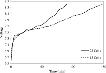
Figure 11. Recharging time profiles for the 12 and 22 module UAVs.
Download figure:
Standard image High-resolution imageTable 7. Comparison of theoretical charging to actual charging results.
| Theoretical fastest recharging time (min) | Actual recharging time (min) | |
|---|---|---|
| 12 module UAV | 74.0 | 149 |
| 22 module UAV | 40.4 | 90 |
5.3. Impact of aerodynamic forces of power output solar cells for sensing
The time-resolved power generated by the multifunctional wings was determined by measuring the voltage and current during flapping. In figure 12(a), results for the 22 module UAV, generating an average of 7.42 W, are compared with the 12 module UAV, generating 4.10 W. The power output was expected to change sinusoidally while flapping, due to its position relative to the Sun. However, the response is not sinusoidal, which indicates the deformation of the wings must have an effect on power output as well. In figures 12(b) and (c), it was found that changes in the power output appear to directly correlate with the thrust generation of the wing, as indicated by the correlation coefficients in table 8. Since it was previously determined that the thrust correlates with in-plane shear strain attributed to the out-of-plane torsional deformations of the wing responsible for the thrust, it is postulated that the change in power output is due to out-of-plane rotation associated with torsional deformations that can reorient cells to increase or decrease their angle of incidence relative to the Sun. The expected relationship is also verified by directly comparing the shear strain with the change in power output for each wing design, as seen in figure 13 along with their correlation coefficients that have been added to table 8. Therefore, the solar cells wings are not only multifunctional in being able to harvest solar energy and serve as skin to generate aerodynamic force during flapping, but it can also be used to sense those forces.
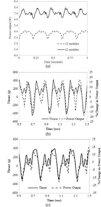
Figure 12. (a) Electrical power generated by the 12 and 22 module UAVs while flapping, and thrust versus % change in power output for (b) 22 module and (c) 12 module UAVs indicating that the solar cells can be used to sense aerodynamic forces.
Download figure:
Standard image High-resolution imageTable 8. Correlation coefficient of the thrust and % change in power output and of the shar strain and % change in power output for the 12 module and 22 module UAVs.
| 12 module UAV | 22 module UAV | |
|---|---|---|
| Thrust/% change in power output correlation coefficient | 0.87 | 0.79 |
| Shear Strain/% change in power output correlation coefficient | 0.69 | 0.67 |

Figure 13. Shear strain versus % change in power output for (a) 22 module and (b) 12 module UAVs directly verifying the expected relationship.
Download figure:
Standard image High-resolution image
The implications of sensing thrust using solar cells has many applications going forward. Gusts of winds can be detected during flights using the same structure that is used to help power the UAV. Thus, this information can be used to change the flapping profile in reaction to the changes in aerodynamic loads. These changes can be potentially automated to allow for correction while it is being piloted or flown autonomously, in which case the wings would be used as smart structures. Because the solar cells are being used to achieve longer flights, being able to adjust to flight conditions using solar cell sensing can be a very powerful new tool for further increasing flight time.
6. Conclusions
This paper investigates the mechanics that affect the potential benefits of introducing multifunctional structures to harvest solar energy on the wings of a flapping wing UAV. We used Robo Raven as our base platform for this investigation. Three different wing designs were initially observed: (1) the regular wings without solar cells, (2) wings with 6 solar cell modules that constitute a 12 module UAV, and (3) wings with 11 solar cell modules that constitute a 22 module UAV. Immediately, a deterioration in flight performance was observed when solar cells were added. The 12 module UAV was still able to fly, but the wings of the 22 module UAV were too stiff and heavy to generate enough aerodynamic lift, resulting in a calculated negative payload capacity. Knowing that deformation plays a major role in force production, the wing design for the 11 module wings was altered, and a modified wing design was developed for the 22 module UAV to recover aerodynamic forces.
With these four wing designs, the force production of each wing design was compared to understand the mechanical effects the solar cells had on the aerodynamic performance of the wing. Therefore, the lift and thrust forces generated by each wing design were quantified. Next, the deformation of each wing surface was quantified while flapping using 3D DIC to determine the specific effects of the mechanical properties of the solar cells as the wing design was varied. There was a clear correlation between the measured DIC deformations and the aerodynamic forces, in particular the correlation biaxial strain associated with the change in aerodynamic shape to the lift force and the correlation of shear strain associated with torsional deformation to the thrust force responsible for providing the forward velocity necessary to generate the aerodynamic lift that enables the UAV to achieve flight. It was also found that changes in power output directly correlated to the thrust, indicating that the multifunctionality of the solar cell wings was not limited to just harvesting solar energy and serving as skin to generate aerodynamic forces, but that they could also be used to sense those forces. Since thrust correlated to shear strain associated with torsional deformation of the wings, it was postulated that these deformations induce out-of-plane rotations that increase or decrease the angle of incidence of the cells relative to the Sun causing the change in power output.
Next, the electrical benefits of adding solar cells were determined. A charging circuit was developed so that the UAV can be charged by the solar cells. The solar cells were also directly integrated to the electrical power of the UAV to extend the operating time of the UAV. A performance model was developed to model the change in operating time due to the integration of solar cells. It was determined that it takes 149 min to completely recharge the battery with 12 solar cells and 90 min to recharge with 22 modules. Theoretically we could have a maximum 13.9% increase in flight time with the 12 module UAV and a 21.2% increase for the 22 module UAV. Unfortunately the model does not take into account the flapping motion of the solar cells nor the heat of running these tests outdoors. We observed a 10.2 and 18.7% increase in operational time for the 12 module and 22 module UAVs respectively. The current solar cells have an efficiency of 5%; however, with recent developments in flexible PV solar cell technology provide more efficient solar cells can be integrated to provide for a longer and maybe infinite flight time. We found we would need a flexible PV solar cell that is 22.5% efficient to achieve infinite flight, and there are flexible PV solar cells that are more than 24% efficient commercially available.
In summary, the fundamental mechanics of adding solar cells to flapping wing UAVs has been established. The added stiffness of the solar cells prevents the wings from deforming resulting in a loss in aerodynamic force generation. The shear and biaxial strains on the surface on the wing were directly correlated to the thrust and lift generated by the wings. This new information is utilized in developing a multifunctional performance model to predict the effects on the flight time of the UAV. Although the stiffness and weight of the solar cells were quantified and determined to have a negative effect on the aerodynamic force production, this was offset by the power generation of the solar cells to result in significant gains in the flight time. From this model, further addition of solar cells to larger wings, the body, or the tail of a UAV can be expected to result in increased flight time. However, the greatest benefit to flight time is expected to result from higher efficiency flexible solar cells, such as thin film GaAs multi-junction solar cells, where a 4.5X improvement in efficiency will theoretically result in infinite flight time and obviate the need for batteries other than as a secondary power source. Finally, it was determined that multifunctional solar cell wings may be capable of three functions: (1) lightweight flexible structure to generate aerodynamic forces, (2) energy harvesting to extend operational time, and (3) sensing of an aerodynamic force associated with wing deformation.
Acknowledgments
This work was sponsored by AFOSR grant FA9550-12-1-0158 with Dr Byung-Lip 'Les' Lee program manager. Opinions expressed are those of the authors and do not necessarily reflect opinions of the sponsors.