
Abstract
We study the transverse magnetic (TM) electromagnetic cavity mode wave functions for an ideal equilateral triangular microstrip antenna (MSA) exhibiting C3v point group symmetry. When the C3v operations are imposed upon the antenna, the TM(m,n) modes with wave vectors  are much less dense than commonly thought. The R3 operations restrict the integral n and m to satisfy
  , where
  and
and  for the modes even and odd under reflections about the three mirror planes, respectively. We calculate the forms of representative wave functions and the angular dependence of the output power when these modes are excited by the uniform and non-uniform ac Josephson current sources in thin, ideally equilateral triangular MSAs employing the intrinsic Josephson junctions in the high transition temperature Tc superconductor Bi2Sr2CaCu2
 , and fit the emissions data from an earlier sample for which the C3v symmetry was apparently broken.
Export citation and abstract BibTeX RIS

Original content from this work may be used under the terms of the Creative Commons Attribution 3.0 licence. Any further distribution of this work must maintain attribution to the author(s) and the title of the work, journal citation and DOI.
1. Introduction
Until very recently, there has been a region in the electromagnetic (EM) spectrum from about 0.1 to 10 THz over which compact coherent sources have been difficult to produce, due mainly to output power P values below 1 mW, the approximate value desired for many applications. This has been especially true in the more limited region 0.3 to 2.0 THz known as the 'terahertz gap' [1, 2]. For emission frequencies f > 2.0 THz, quantum cascade lasers (QCLs) are operational at the desired power values without cryogenic cooling [3–5]. Schottky diode frequency mixers, backward-wave oscillators, and frequency multiplier chains are operable for  THz [6, 7], and intracavity difference frequency generators operate over the f range of 2.6–4.2 THz [8]. Resonant tunneling diodes (RTDs) have been able to operate with sufficient power for f < 1.4 THz at room temperature [9, 10], but recently were shown to emit up to 2.0 THz, albeit at P values around 1 μW [11, 12].
A completely different type of source operating in the sub-THz to THz range is due to the ac Josephson effect [13, 14]. The extremely anisotropic, layered, high-transition temperature Tc superconductor Bi2Sr2CaCu2 (Bi2212) consists of regularly alternating superconducting and insulating layers [15–17], each of which acts as an intrinsic Josephson junction (IJJ). The best samples of Bi2212 are grown by a modified travelling-solvent floating zone technique [18, 19]. When a dc voltage V is applied across the stack of N active IJJs, it gives rise to an ac current and the emission of a photon at the frequency
  due to the ac Josephson effect, where e and h are the electronic charge and Planck's constant, respectively [13]. In addition, a Bi2Sr2CaCu2
 mesa structure fabricated from the top of a single crystal behaves as an electromagnetic (EM) cavity, the modes of which depend upon the geometric shape of the mesa [20]. By varying the bias V, the output f changes until it locks onto a standing wave mode of that EM cavity, resulting in coherent emission from the stack of IJJs at f = fc(m, n), where fc(m, n) is the frequency of the EM cavity mode indexed by the two integers (m, n) for the particular cavity geometry, enhancing the output power at that f value [20–37]. Two reviews of this phenomenon were recently published [38, 39].
However, the introduction of a dc current I into the mesa has also led to severe Joule heating problems, resulting in the formation of inhomogeneous hot spots over which the local temperature  [40–56]. This Joule heating also caused the restrictions V < 1.5 V, f < 1.0 THz, and
  W from a single mesa [57–60], although a three-mesa array was reported to have a combined emission P of 0.6 mW [61].
Direct competition with the latest RTD devices [11, 12] has arisen from the construction of 'stand-alone mesa sandwich structures'. These are fabricated from a Bi2212 mesa by cleavage from its Bi2212 substrate, depositing Au films on both its top and bottom, and then sandwiching it between two insulating plates [62–65]. These sandwich structures allow for much more efficient Joule heat removal in the IJJ emitter devices, allowing bias V values up to 7 V and f values up to 2.4 THz, with strong emissions at particular frequencies above 1 THz [62–67]. Strong enhancement of the output power at particular (probably EM cavity) frequencies was also seen in a non-sandwiched rectangular stand-alone mesa [58]. Emission from mesas with slightly different heat removal designs while immersed in liquid nitrogen has also been observed [68, 69]. Although the local  maps of these stand-alone mesa sandwich devices have not yet been measured, the IV characteristics have been shown to exhibit far fewer features associated with heating effects [65], so the best stand-alone mesa sandwich devices are likely to be considerably more thermally homogeneous than were the previous 'conventional' ones. However, we note that since the Bi2212 sample is removed from its Bi2212 substrate, the IJJ emitter is no longer a mesa, but is instead a microstrip antenna (MSA), so a more accurate name for the device is 'thermally-managed IJJ MSA'.
The important question of the sample homogeneity was raised by comparing the results of thin cylindrical (disk) conventional mesa IJJ emitters and thermally-managed IJJ disk MSAs [49, 55, 64, 70, 71]. In three conventional disk mesas, the strongest emission was observed at that of the lowest frequency TM(1,1) disk mode, the wave function of which has a line node passing through the disk center at some angle. Since the angular dependence of the output was only measured in two perpendicular planes normal to the mesa, the question of the possible azimuthal emission anisotropy was left unanswered [70]. Moreover, in a more recent thermally-managed IJJ disk MSA using sapphire as the insulating plates, only very weak emission was observed at that TM(1,1) mode frequency [64]. Instead, the strongest emission was observed at about 1.0 THz, which is intermediate between the expected emission frequencies from the TM(0,1) and TM(2,1) disk modes, and a secondary strong peak was observed at 1.6 THz, near to the expected TM(1,2) and TM(4,1) disk mode emission frequencies [64]. The disk TM(0,1) wave function exhibits the full rotational symmetry of the  point group appropriate for a perfectly homogeneous disk, whereas the disk TM(1,1) and TM(2,1) wave functions do not [72, 73]. Although experiments to measure the angular distribution of the radiation at 1.0 THz and 1.6 THz have not yet been made in that or related samples due to the presence of a surrounding copper holder containing a Si lens [65], a possible explanation consistent with the reduced heating effects in the present samples could be that the inhomogeneous heating in the earlier conventional mesas broke the
  rotational symmetry of ideal disk MSAs, but the thermally-managed disk IJJ MSAs are thermally much more homogeneous, and are more likely to exhibit
  symmetry [65]. As noted above, the Au top and bottom layers also appear to amplify the emission power at the particular EM cavity mode frequencies [58], making the study of EM cavity mode emissions very important for the development of useful devices.
With regard to the emissions from thin IJJ emitters with shapes other than disks or rectangles, there have been studies of the emissions from thin equilateral, right isosceles, and acute isosceles triangular conventional Bi2212 mesas [74–76]. Three equilateral triangular (ET) mesas all showed strong emissions at the frequency of the ET cavity TM(0,1) mode, which is six-fold degenerate, with three even and three odd parity modes about each of the mirror planes bisecting one of the angles. However, as indicated in figure 1 and table 1, a perfectly homogeneous equilateral triangle has C3v point group symmetry, and the actual wave function must not only satisfy the Helmholtz (or wave) equation and the appropriate transverse magnetic boundary conditions, it must also satisfy either even or odd parity about all three of the mirror planes, and invariance under R3 and  , or respective rotations by
  and
and  about the axis perpendicular to the ET plane passing through its geometric center. For an odd number of R3 rotations for all points to return to their original positions (the identity operation), only the +1 eigenvalue of the R3 operation is allowed. As shown in the following, the wave functions of the three even nominally fundamental ET TM(0,1) modes and the three odd nominally fundamental ET TM(0,1) modes both sum to zero at every point inside the triangle! Hence, the only reason one might have observed strong emission at the frequency corresponding to that TM(0,1) mode would be that the C3v point group symmetry was broken in those samples. If the symmetry-breaking operation were inhomogeneous heating, then removal of these heating inhomogeneities might allow us to probe higher frequency modes, as occurred recently in thermally-managed IJJ disk MSAs [64]. This could enable us to produce arrays of thermally-managed IJJ ET MSAs that might emit at the fundamental C3v-symmetric ET TM(1,1) mode frequency and at higher group-symmetric ET mode frequencies, potentially at output powers strong enough for practical devices.

Figure 1. Sketch of an equilateral triangle of side a, with the center of gravity at the origin O, the intersections of the  mirror planes with the triangular plane, and one of the R3 rotation operations [84].
Download figure:
Standard image High-resolution imageTable 1. C3v point group symmetry table.
| Representation | I |  |
R3 |
|---|---|---|---|
| A1 | +1 | +1 | +1 |
| A2 | +1 | −1 | +1 |
Note: I is the identity operation. The  are the three mirror planes perpendicular to the triangle surface that bisect one of the angles and its opposite side. R3 is the rotation operation by
  about the perpendicular axis passing through the geometric center.
2. Wave functions with C3v point group symmetry
The case of C4v point group symmetry for a square planar lattice was studied in detail with regard to the orbital symmetry of the superconducting order parameter in the cuprates such as Bi2212 [77]. In that case, the group symmetry operations were the identity, the  and
and  mirror planes normal to the x and y axes, the diagonal
  and
and  mirror planes, and the R4 rotation of
  about the geometric center. There were four spin-singlet even symmetry orbital pair states that were allowed, those having s-wave,
  , dxy, and
  symmetries. Breaking the C4v symmetry by a transformation from the tetragonal structure to an orthonormal structure of either the
  (appropriate for YBa2Cu3
 ) or
) or  type (approximately appropriate for Bi2212) allowing unlimited mixing of s and
  and of dxy and
  order parameters in the former case, and unlimited mixing of s and dxy and of
  and of
  in the latter case. Further mixing could only arise with a second phase transition [77], which could be either a structural transition or a second superconducting phase transition, neither one of which was ever observed in either material, although charge-density waves are likely to exist above Tc in both materials [78]. This broken C4v point group symmetry of the superconducting orbital order parameter would lock onto the crystal lattice, so that if the superconducting gap were anisotropic, its expected anisotropy would be compatible with some rectangular or disk cavity modes, but would be incompatible with C3v-symmetric ET cavity modes.
2.1. Equilateral triangular mesa wave functions
The equilateral triangle has been of general interest for at least two millenia, but the first paper to study the wave functions for it with Dirichlet and von Neumann boundary conditions was by Lamé in 1833 [79]. In such a high-symmetry structure, separation of variables was shown to lead to trigonometric functions of the two variables, and the boundary conditions could be applied on all boundaries [79]. However, it was difficult to plot the wave functions without the use of modern computers, and the development of symbolic manipulation software has greatly facilitated our ability to study and to produce plots of them.
A sketch of a thin equilateral triangular mesa of side a is shown in figure 1. The origin is taken to be the center of gravity O, and hence the corners are at  ,
,  ,
,  [80–86]. For a perfect equilateral triangular patch antenna, the wave functions must obey all of the C3v point group operations, which are summarized in table 1 and also indicated in figure 1. A
  table of the group operations (including the
  ) is given in textbooks [87, 88].
In the modern era, Helszajn and James [80] first wrote down the general form for the wave function satisfying von Neumann boundary conditions, which is appropriate for the magnetic vector potential Az produced by the Josephson current normal to the layers of Bi2212. The wave function  represents Az, from which the electric field Ez is calculated, and the relevant von Neumann boundary conditions are the transverse magnetic ones, for which the normal derivative of the wave function must vanish on all portions of the boundary of the object, which in this case is an equilateral triangular (ET) microstrip antenna (MSA). They assumed one contribution
  to the magnetic vector potential Az(x, y) (i.e. the wave function) to have the form [80]
where  and n are integers. This form exhibiting elementary separation of the variables x and y is an even function under group operation
  , which intersects the ET plane with the line passing between the origin and the corner at A, as sketched in figure 1. Although each of these three terms satisfies the Helmholtz (wave) equation by inspection, it is necessary to include all three to satisfy the TM boundary conditions on all three sides of the triangle [80–84]. In addition to
  , there is another form exhibiting elementary separation of spatial variables,
which is odd about  [84]. Although this form was not discussed by Helszajn and James [80], an example of this odd function was sketched by Overfelt and White [81]. We note that the action of the rotation operator R3 on
  is equivalent to counterclockwise cyclic permutation of the indices:
  .
.
Since each term in either of these wave function forms must independently satisfy the wave equation, we obtain three equations for the same wave vector k. Setting them equal to one another, we obtain the equation  , so we can eliminate
  by setting
  from the wave functions without ambiguity [80, 84], as the only alternative solution which is consistent with the wave equation, m = n, has been shown to provide no new eigenfunctions [82, 83, 85, 86]. Then,
and
where we have introduced the normalisation constants  .
.
In order to simplify these normalisation and subsequent surface current integrals, we use the notation  and
and  .
.
We may normalise  by direct integration [82, 86], requiring that

where  indicates that the integration region is over the interior of the ET area. We thus obtain
From figure 2, we can also construct 
![${{R}_{3}}\left[\psi _{mn}^{(e,o),(1)}(x,y)\right]$](https://content.cld.iop.org/journals/0953-8984/29/1/015601/revision1/cmaa40a7ieqn061.gif) and
and ![$\psi _{mn}^{(e,o),(3)}(x,y)={{R}_{3}}\left[\psi _{mn}^{(e,o),(2)}(x,y)\right]$](https://content.cld.iop.org/journals/0953-8984/29/1/015601/revision1/cmaa40a7ieqn062.gif) by successive 120° rotations about the origin of the spatial variables. These functions will be respectively even and odd about mirror planes
by successive 120° rotations about the origin of the spatial variables. These functions will be respectively even and odd about mirror planes  and
and  . It is shown in [84] that both even and odd
  also satisfy the boundary conditions, necessitating a superposition of these three degenerate wave functions for each even and odd TM(m, n) mode in order to satisfy the R3 symmetry of the group,

where the  are constants. This general form for a TM cavity mode can be used to model the symmetry breaking effects of hot spots and local defects (e.g. a linear mixture of the degenerate TM(1, 0) odd and even modes pictured in figure 2. For an ideal mesa, however, the cavity mode wave functions must also satisfy the R3 symmetry operations of the group in order to be an orthonormal set [85], requiring
  . It is easy to show using symbolic manipulation software that


Figure 2. Colour-coded contour plots of the normalised (a) TMe,(1)(10) even and (b) TMo,(1)(1, 0) odd mode wave functions  and
and  , respectively, of an equilateral triangular mesa, which are two of the six degenerate ground state wave functions in the case of broken C3v symmetry.
Download figure:
Standard image High-resolution imageThis is pictured graphically for  in figure 3. In fact, this is true for most of the wave functions. Examining this C3v symmetric superposition, we find that the only modes that do not vanish identically inside the triangle are those for which


Figure 3. Colour-coded contour map illustration of equation (8) for the normalised TMe(10) modes, 
 at every point inside the triangle.
Download figure:
Standard image High-resolution imageThus, only the even wave functions can have m = n. In fact, the only  satisfying equation (9) are those for which
  itself possesses R3 symmetry, i.e.
  .
.
Therefore, the ground state of an ideal ET mesa or any other ET microstrip antenna (MSA) for TM boundary conditions is the TMe(1, 1) mode pictured in figure 4. The degenerate first excited state TMe(0,3) and TMo(0,3) mode wave functions are shown in figure 5, the non-degenerate second excited state TMe(2,2) mode is shown in figure 6, and the degenerate TMe(1,4) and TMo(1,4) modes are shown in figure 7. These functions were plotted from the appropriate  , and the reflection and rotation C3v group symmetry operations are immediately obvious to the observer. The next 21 highest frequency wave function plots are given in the supplementary material (stacks.iop.org/JPhysCM/29/015601/mmedia) to illustrate the behavior of the higher modes which satisfy the C3v group symmetry. When the R3 C3v point group symmetry operation is broken, the three odd and three even TM(1, 0) modes become the degenerate ground states, and all of the wave functions for arbitrary n, m can be excited.
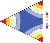
Figure 4. Colour-coded contour plot of the normalised TMe(1, 1) mode wave function, the ground state of an ideal (i.e. C3v symmetric) equilateral triangular mesa.
Download figure:
Standard image High-resolution image
Figure 5. Contour plots of the normalised degenerate TMe(0, 3) even (left) and TMo(0, 3) odd (right) first excited state mode wave functions of an ideal equilateral triangular mesa.
Download figure:
Standard image High-resolution image
Figure 6. Colour-coded contour plot of the normalised TMe(2, 2) even mode wave function, the second excited state of an ideal equilateral triangular mesa.
Download figure:
Standard image High-resolution image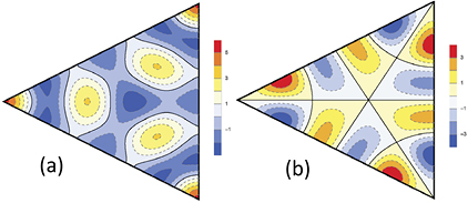
Figure 7. Colour-coded contour plots of the normalised degenerate TMe(1, 4) even (left) and TMo(1, 4) odd (right) third excited state mode wave functions of an ideal equilateral triangular mesa.
Download figure:
Standard image High-resolution image3. Radiation from ET mesas
As first discussed with regard to rectangular and disk mesas [71–73] for the emission from the intrinsic Josephson junctions in Bi2Sr2CaCu2 , there are two radiation sources [89]. The primary radiation source is the uniform ac Josephson current source, and the secondary source is due to the excitation of an electromagnetic cavity mode [71–73, 89]. In both cases, the Love equivalence principles allow one to replace the magnetic fields inside the MSA by surface integrations of the equivalent uniform electric and magnetic current surface currents [89]. For a thermally-managed IJJ MSA structure, the gold layers on top and bottom of the thin Bi2212 crystal force the emissions to occur from the sample edges, so that these Love equivalence principle approximations are expected to be highly accurate.
3.1. Primary ac Josephson radiation source
For the uniform current source, the magnetic vector potential is obtained from the uniform part JJ of the ac Josephson current integrated around the surface of the MSA [73, 89], which at the emission frequency fnm of the TM(n, m) cavity mode(s) becomes

In the surface integral  , we make an integration around the circumference of the ET MSA, and assume the thickness h of the antenna is vanishingly small. Thus, this becomes a line integral around the circumference of the equilateral triangle of the phase factor
  . We choose to start at the point C in figure 1, and make a counterclockwise path on the ET MSA circumference. Thus, in this configuration, the integration path vectors
  ,
,  , and
, and  are
are
However, in order to ensure that the three unit segments have equal lengths, it is useful to take the  path by rotating the triangle clockwise by 30°, going horizontally from right to left from
  to
to  , and for the
  path, we rotate the triangle counterclockwise by 30°, going horizontally from left to right from
  to
to  , as shown in figure 3 of [84]. In these rotated coordinates, we have
and inverting these equations, we obtain the necessary transformations,
In the integrations over the phase factors  , we write
  in spherical coordinates relevant to the far-field regime. Thus, the three integrations may be written as

For the TM(m,n) mode, we have outside the source that

where  is the index of refraction of Bi2212 in the appropriate emission frequency range [38, 71, 73]. Thus, we are motivated to define the quantities
The magnetic vector potential  for the uniform current source is readily found using (15)–(18),
where  in the radiation zone. From this expression for
  , we obtain the electric and magnetic fields
  and
and  . The angular distribution of the emission power obtained from the uniform current source alone is then given by the time average of
  , which is proportional to
We examine the angular dependence of the radiated power  due to the primary ac Josephson radiation source by plotting equation (24) for various integral m and n values. Spherical plots of the power emitted from the uniform ac Josephson current source at the lowest symmetry-broken TM(0,1) and lowest C3v-symmetric TM(1,1) mode frequencies f01 and f11 are shown in figure 8. Although these frequencies differ by the factor of
  , with nr = 4.2, the wavelength is considerably larger than the MSA in both cases, so the patterns are difficult to distinguish. Spherical plots of the power emitted from the uniform ac Josephson current at the next three lowest C3v-symmetric frequencies f03, f22, and f14 are shown in figures 9 and 10. For nr = 4.2, there is very little difference in the emission distribution from the uniform source at the lowest three emission frequencies f11, f03, and f22. However, the emission pattern at the third excited state frequency f14 is quite different from those three, as the wavelength of the 3D emitted photons is comparable to the size of the source MSA. In the supplementary material, we plotted the 3D emission patterns for the next 21 highest cavity frequencies, and each of those are distinctly different from one another and from those pictured in figures 8–10.
Figure 8. Plots of the uniform source contributions to the power radiated from (a) the broken-symmetry ground state TM(1,0), and (b) the C3v symmetric ground state TMe(1,1) mode. The arrows marked  indicate the
  direction in figure 1.
Download figure:
Standard image High-resolution image
Figure 9. Spherical plots of the output power arising from the uniform ac Josephson current source at (a) the first f03 and (b) the second excited C3v-symmetric state f22 mode frequencies.
Download figure:
Standard image High-resolution image
Figure 10. Spherical plot of the output power arising from the uniform ac Josephson current source at the third excited C3v-symmetric state f14 mode frequency.
Download figure:
Standard image High-resolution image3.2. Secondary cavity mode source
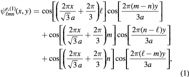
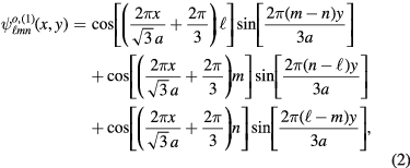
The electric potential  is calculated from the magnetic surface current density source
  using
using

where  is the displacement current along the edges of the triangle multiplied by the wave function of a particular excited cavity mode. As for the disk [72, 73],
  is the edge path weighted by the wave function of the particular cavity mode. Thus, we have

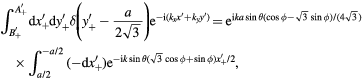
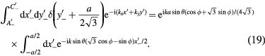
where  ,
,  , and
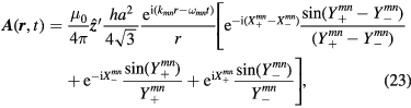
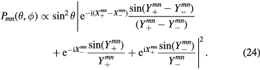
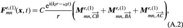
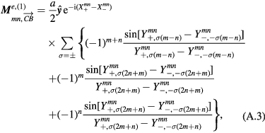
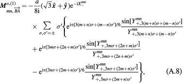
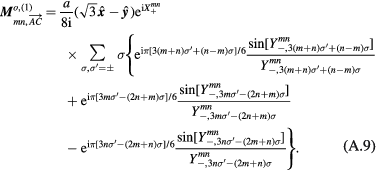
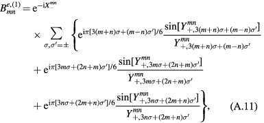
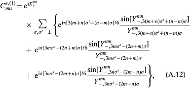
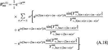
, and  are given by equations (12)–(14). Since each of the integrals is a combination of elementary exponential functions, the general expression for each cavity mode can be obtained analytically, and hence an analytic expression for the angular distribution of the output power can also be obtained. However, due to their complexities, those analytic results are listed in the appendix. The relevant quantities are
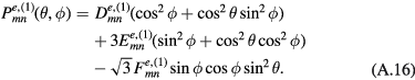
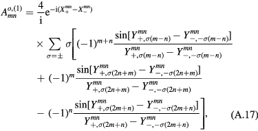
  given by equations (A.16) and (A.23) in the appendix.
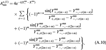
For the cavity mode source radiation under the assumption of broken C3v symmetry, the TM(1,0) ground state is six-fold degenerate, since an even and odd parity mode is admitted for each of the three mirror planes of the C3v point group. As stated in appendix equations (A.24) and (A.25), the power distributions for each pair of even and odd modes differ only by rotations in R3. One such pair of degenerate power distributions for the TM(1,0) fundamental,  and
and  , is plotted in figure 11. The nodes in the figures straddle the wave function nodes in figure 2.

Figure 11. Plots of the power radiated from the degenerate non-C3v-symmetric cavity modes, the TM(1)(1,0) (a) even and (b) odd modes. The arrows marked  indicate the
  direction in figure 1.
Download figure:
Standard image High-resolution imageIn the case of an ideal ET MSA, however, the entire C3v point group symmetry must be satisfied, resulting in a distinct TM(1,1) even ground state pictured in figure 4. The even and odd cavity mode power distributions for a general TM(m,n) mode are plotted using appendix equations (A.10)–(A.23); the three lowest frequency examples of the emission power distributions from C3v-symmetric cavity modes are presented in figures 12–14. The emission distributions from the 21 next-higher frequency C3v-symmetric cavity modes are presented in the supplementary material.

Figure 12. Spherical plots of the power radiated from the C3v symmetric (a) TMe(1, 1) even ground and (b) TMe(2, 2) even second excited state cavity modes. The arrows indicate the  axis in figure 1.
Download figure:
Standard image High-resolution image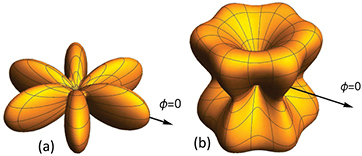
Figure 13. Spherical plots of the power radiated from the C3v symmetric (a) TMe(3, 0) even and (b) TMo(3, 0) odd degenerate first excited state cavity modes. The arrows indicate the  direction in figure 1.
Download figure:
Standard image High-resolution image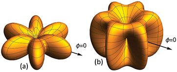
Figure 14. Spherical plots of the power radiated from the C3v symmetric (a) TMe(4, 1) even and (b) TMo(4,1) odd degenerate third excited state cavity modes. The arrows indicate the  direction in figure 1.
Download figure:
Standard image High-resolution image4. Fit to the emissions data from a thin ET conventional mesa
We now fit experimental data for the angular dependence of the emission intensity  from a thin ET conventional mesa of Bi2212 with the dual source radiation model presented in section 3 using a two-parameter least squares fit. The sample studied was sample no. 3 of [74], which is a groove mesa of side length
  m, thickness
  m, and (underdoped) transition temperature
  K. An optical image of the sample prior to the electrical lead attachments is shown in figure 15. The emission frequency at dc bias voltage V = 0.91 V was at f = 0.53 THz at 40 K, which is in the low-bias current
  mA 'retrapping' region. More details are given in figures 2 and 3 of Delfanazari et al [74]. Based on the resonant frequency of the emission [74], we conclude that C3v symmetry is broken for the sample, as this f value is consistent with one or more of the lowest-energy TM(e,o),(i)(1,0) modes. Here we present the angular dependence of the emissions under those conditions, and fit the data using

where the  factor takes account of the Bi2Sr2CaCu2
 substrate [72, 73], which was found to be necessary include in order to fit conventional mesas. This factor arises from treating the substrate as a perfect magnetic conductor [89]. In the fits, A, B are the fitting parameters, P10 is the uniform source power distribution equation (24), and the
  are any one of the six cavity mode power distributions in equations (A.16) and (A.23) for the degenerate TM(1,0) modes listed in the appendix. We subsequently found that the TMo,(2,3)(1,0) odd and TMe,(1)(1,0) even cavity modes, which correspond to the power distributions
  and
and  , resulted in the most accurate fits. For the TMo,(2)(1,0) mode, the fitted values were
  and
and  and the standard deviation was
  . For the TMe,(1)(1,0) mode, the fitted parameters were
  ,
,  , and
, and  . These results are statistically indistinguishable. Although the precise values of the amplitudes of each function are not included in these fits, we can integrate the two angular functions separately. We thus determined that 58% of the emission was due to the excitation of some of the TM(1,0) cavity modes.
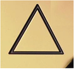
Figure 15. Optical image of equilateral triangular groove mesa, sample 3, that was used in the angular distribution studies [74].
Download figure:
Standard image High-resolution imageThe results of these two least squares fits are displayed in-plane with the experimental data in figures 16 and 17, while the full angular distribution  of the fits are given in figure 18.

Figure 16. Plots of experimental data (blue, magenta, violet) and the least squares fit (black) to the TM(1)(1,0) even mode for an equilateral triangular mesa in the (a) xz and (b) yz planes.
Download figure:
Standard image High-resolution image
Figure 17. Plots of experimental data (blue, magenta, violet) and the least squares fit (black) to the TM(2)(1,0) odd mode for an equilateral triangular mesa in the (a) xz and (b) yz planes. The same results are also obtained by using the TM(3)(1,0) odd mode for the cavity mode contribution.
Download figure:
Standard image High-resolution image
Figure 18. Least squares fits to the angular dependence of the emission intensity  from an equilateral triangular mesa to (a) the TM(1)(1,0) even mode (b) the TM(2)(1,0) odd mode, both using the superconducting substrate factor.
Download figure:
Standard image High-resolution image
5. Summary and discussion
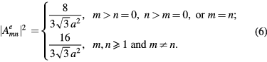
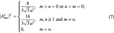
In summary, we have shown that the C3v point group symmetry of an ideal ET MSA plays a vital role in the density of allowed TM modes. The R3 operations require that, for an ideal ET MSA,  , where
  and
and  for the even and odd modes, respectively. Consequently, the nominally fundamental TM(1,0) odd and even mode wave functions both vanish, and the ground state for an ideal equilateral triangular microstrip antenna is the TM(1,1) mode, unless the R3 symmetry is broken in some manner.
We have fit experimental data for the angular dependence of the radiated intensity from a thin ET conventional groove mesa with the theoretical output power due to the excitation of the TM(1,0) mode. Use of either the  or
or  cavity mode power distributions in the fitting equation (27) gives the most accurate result, with about 58% of the power arising from the TM(1,0) cavity mode with a standard deviation of
  in the fits.
Our results for the ET MSA also suggest a possible explanation for the difference between the lowest resonant frequencies of conventional disk and thermally-managed IJJ disk MSA devices [64, 70]. In three conventional disk mesa samples, the emissions were found to correspond to the  -symmetry violating TM(0,1) mode [70]. But in a thermally-managed IJJ disk MSA device, almost no emission was seen at the frequency of that mode, but the strongest emission was observed at 1.0 THz [64], corresponding to either the rotationally-invariant
  -satisfying TM(0,1) disk cavity mode or the
  -violating TM(2,1) disk cavity mode. In addition, the second-strongest emission at 1.6 THz corresponds approximately to the excitation of the nearly-degenerate TM(4,1) and TM(1,2) modes. The simplest explanation would be that the greatly reduced heating effects in the stand-alone mesa sandwich structures allow for much more homogeneous samples [65], suggesting that the TM(0,1) was probably observed at 1.0 THz [64]. But to confirm this, angular distribution studies of the emissions from themally-managed IJJ disk MSA devices need to be performed.
We remark further that if Bi2Sr2CaCu2 were to have a significant amount of superconducting gap anisotropy as regards the c-axis Josephson tunnelling of the internal junctions, then one would expect that anisotropy to be evidenced by the particular cavity mode excited. Thus, a gap function with four-fold gap anisotropy (such as for a predominant
  -wave or extended-s-wave superconducting order parameter), should favor the excitation of the TM(2,1) and TM(4,1) modes. But since the gap anisotropy is fixed to the crystal lattice, the resulting emissions should also be fixed to the lattice, if that were the case. Hence, azimuthal angular distribution studies of the strong emissions in stand-alone disk mesa sandwich structures should determine whether or not there is any preferred anisotropy to the superconducting gap in the bulk of the Bi2Sr2CaCu2
 samples.
Due to the sparsity of the C3v symmetric cavity modes in themally-managed IJJ ET MSAs, we predict that a lower-symmetry alternative structure such as thermally-managed IJJ pie-shaped wedge MSAs will provide wider tunability [74]. However, high-symmetry MSAs such as the thermally-managed IJJ ET MSAs could allow for a probing of the higher frequency modes of the equilateral triangle. One advantage of ET MSAs is that they can be easily fit together to make arrays [90], since six of them can be fit closely together forming a regular hexagon. Although the lower emission frequencies would not be very tunable, the coherent output from thermally-managed IJJ ET MSAs could be large enough for practical applications, and some amount of tunability could arise from varying the current-voltage characteristic point and the temperature [58, 63–65]. Provided that a substantial amount of residual heating effects in thermally-managed IJJ ET MSAs can be eliminated, one could probe the beautiful spectra of and emissions from the C3v-symmetric modes of ET MSAs.
Acknowledgments
A Gramajo was supported in part by the UCF RAMP program. C Watanabe was supported by a JSPS Research Fellowship for young scientists. This work was supported in part by CREST-JST (Japan Science and Technology Agency) and WPI (World Premier International Research Center Initiative)-MANA (Materials Nanoarchitectonics) project (NIMS).
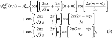
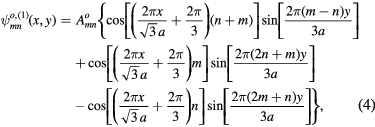
: Appendix
Here we present the analytic results for the angular distribution of the emission of radiation from an equilateral triangular MSA. For Bi2212, one needs to set  , which makes the lower frequency output distributions nearly azimuthally isotropic.
For the magnetic surface current density (or cavity) source, we define the generalized functions

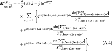
where  is given by equation (22) in the text. Then, the magnetic current source contributions obtained from the three sides of the equilateral triangle for the even TM(m, n) modes are
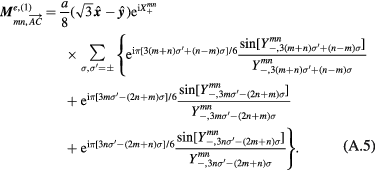
The corresponding odd terms are:
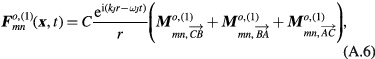
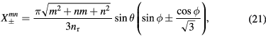
The power obtained from the even symmetry modes is then found to be


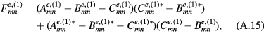
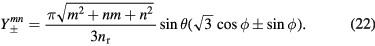
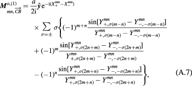
Similarly, the odd mode power distributions are given by
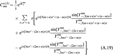


We note that like the corresponding wave functions, the power distributions satisfy

