
Abstract
After a brief history of the Levitron, the first horizontal axis Levitron is reported. Because it is easy to operate, it lends itself to educational physics experiments and analogies. Precession and nutation are visualized by reflecting the beam from a laser pointer off the 'spignet'. Precession is fundamental to nuclear magnetic resonance, magnetic resonance imaging, particle traps and the movement of bodies in space. Longitudinal and lateral bounce behaviour is explained via 'the principle of gentle superposition' of two traps: the micro-precessional and the macro-trap. Theory is initiated. Scaling experiments are mentioned. Industrial applications might follow.
Export citation and abstract BibTeX RIS
1. Introduction: short history of the Levitron
In a sense, the history of the Levitron1 commences in 1842 with the work of the Cambridge 'don' Earnshaw [1]. Earnshaw deduced that there can be no static equilibrium for bodies obeying the inverse square law and that therefore everything has to be in motion or in contact. Mathematically written, the sum of the second differentials of a potential in free space (according to Laplace) is nil,

At least one of these terms must be negative, and instability results in the corresponding direction. Earnshaw's theorem is valid for most static electric, magnetic or gravitational fields. It does not apply to superconducting or diamagnetic materials. Luckily, Harrigan [2] realized that contrary to advice given by physicists, 'Earnshaw' does not apply to spinning bodies. His inspired demonstration 'against all odds' of the freely spinning levitated magnetic top was patented in 1983. E W and W G Hones [3] marketed and propagated the 'Levitron'. However, progress with experiments and theory was slow. Only minor experimental changes were made—chiefly to the magnetic base. Ring magnets rather than square were employed (figures 1(a) and (b)), and with the advent of cheap and stronger magnets (neodymium versus ferrite) impressive levitation heights of nearly 10 cm (as opposed to two or three) were demonstrated and commercialized. However, the Levitron, in the words of Romero [4], was never 'anything other than a scientific toy' but which could 'in fact have practical applications'.
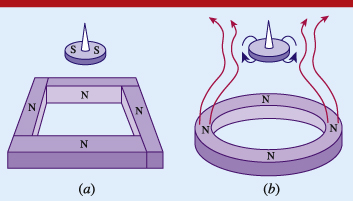
Figure 1. Two magnetic levitation geometries: (a) the square base Levitron and (b) the ring base Levitron and associated field lines (schematic).
Download figure:
Standard image High-resolution imageEarly theory was misleading. The correct stabilization mechanism was first proposed in 1996 by Berry [5] and clearly elucidated for the more general reader by Simon et al [6] in 1997. Berry also drew attention to the similarity between the Levitron and the Paul trap for neutral magnetic particles. In 2012, the present writer demonstrated inclined Levitron operation [7]: steady inclination at angles up to 45° and rotating inclination, made visible by reflecting a laser pointer off the Levitron in either the strongly precessing mode or the nutating one. While some debate took place in the blog-world about the possibility of operating a horizontal axis Levitron, it was generally felt that this would not be possible, although one blogger did suggest using a centrifuge to simulate near-horizontal gravity, a challenging experiment to perform. Romero did publish a mathematical treatise on 'spin stabilized magnetic levitation of horizontal rotors' [4] in 2003, but the proposed experimental programme does not seem to have been undertaken.
In this paper I report the first operation of a horizontal axis Levitron and show how its behaviour is similar to that of the vertical axis Levitron in some expected respects but very different in others. This difference in behaviour allows it to become an educational tool.
2. Demonstration of a horizontal axis Levitron: from 45° to 90° inclination
With a magnetic 'V' and two 'puller' and 'pusher' magnets it is quite easy to levitate a 'spignet' at inclination angles of around 30°. With a pair of 'outrigger magnets' it is even possible to get to inclinations of 45°: figure 2. However, beyond 45°, the spignet either jumps out of the trap or falls into the 'V'.
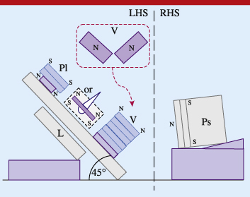
Figure 2. The inclined Levitron. On the left-hand side (LHS) micro-confinement is achieved with the habitual Levitron base and in addition a 'V', a 'puller' (Pl) and two 'outrigger' (Or) magnets. To reach an inclination of 45° an additional 'pusher' (Ps) magnet has to be mounted on the right-hand side (RHS). The pusher serves two purposes: it helps to push the Levitron up the slope and it increases the effective gravitational force to compensate for the reduction caused by inclination. The 'V' angle is about 90° (inset).
Download figure:
Standard image High-resolution imageTo achieve horizontal axis operation, a totally different approach was needed to the triple problem of supporting the spignet against gravity, of confining it in a macro-trap and, most importantly, of organizing the horizontal field for the precessional micro-trap. (See the theory section.)
Once the necessity of satisfying these triple requirements had been grasped, the beginnings of horizontal axis Levitron (HAL) became apparent. The first and second requirements could be attempted with the same 'V', 'puller' and 'outrigger' magnets as used for the inclined Levitron. These three sets of magnets give the spignet lift and prevent it from escaping sideways by forming a macro-trap. A pair of large slab magnets forming a large 'V' generates the horizontal field for the micro-trap: figure 3. They also contribute to lift. With this set of seven magnets in place, there was an inkling of horizontal trapping: the spignet would hover and sometimes violently precess in the trap for less than 2 s.

Figure 3. The magnetic geometry for the horizontal axis Levitron; two large inclined slab magnets at about 70° complement the 'V', puller and outrigger magnets mounted on a vertical sheet of Perspex. The slabs generate the strong horizontal field needed to create the Berry/SHR micro-trap. The puller magnets act as a suspension point for the axial pendulum-like oscillations of the spignet. The 'V' and puller magnets cancel gravity and the outriggers prevent the spignet from escaping sideways.
Download figure:
Standard image High-resolution imageIt only remained to find a 'Kunst-Griff' (clever-trick) to get this system to work. From a situation where equilibrium was only fleetingly divined, the Kunst-Griff excitingly extended the confinement to several seconds and progressively, with more precise positioning of all the magnets, to well over 1 min, exactly like the vertical Levitron. The Kunst-Griff consists of mounting the puller magnets about 1 cm away from the supporting plate so that the spignet is given a chance of falling into the horizontal trap.
This simple trick can be enhanced by shifting the support plate a few millimetres, once the spignet has been launched. The puller magnets behave like a pendulum support, with the spignet bouncing to and fro about a vertical line drawn between the puller magnets and situated about 1.5 cm from the vertical plate. After a few axial oscillations, the spignet settles down in the axial potential well. To the unaided eye it appears to be perfectly horizontal and stationary: figure 4. After some 30 s, as air resistance slows the spignet, it starts to gently wobble. After nearly 2 min, the wobbles grow and the spignet jumps onto one of the trapping magnets.
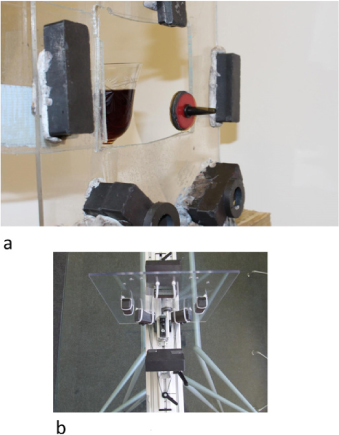
Figure 4. First published pictures of the horizontal axis Levitron. (a) Horizontal spignet: visible are the 'outrigger' magnets, the right-hand arm of the 'V' (below) and part of the 'puller' (above), all mounted on a Perspex plate. Some flexible putty gives the magnets the correct elevation above the plate. The spignet is launched by spinning it against a 'window' which can be opened once the spignet is floating freely. A glass of wine was placed behind the open window for verification of the horizontal plane. (b) HAL toy prototype (viewed from above). Visible are the two large slab magnets, the small 'V', the outriggers, the puller and the spignet.
Download figure:
Standard image High-resolution imageOne important feature of HAL is that it is far easier to operate than the vertical axis Levitron (VAL). A commercial prototype has now been tested (c/o Oxford Product Design—ISIS). Whereas it can take up to an hour to master VAL, most people succeed with the commercial HAL after a couple of minutes. Also, VAL requires continual mass adjustment to account for the change of magnetic moment with temperature: little discs are supplied so that, by trial and error, levitation remains successful. No such adjustment is necessary with HAL. Also, HAL is more robust. The slightest draught destabilizes VAL, whereas one can even gently touch HAL while it spins. The reason for this remarkable stability is that, as explained in the theory section, a macro-trap is superposed on the precessional micro-trap. The macro-trap allows the spignet greater lateral bounce behaviour (approximately 1.5 cm rather than 5 mm). The longitudinal pendulum-like trap determined by the magneto-static field of the puller and pusher magnets is similarly generous: a centimetre rather than millimetres. Once correctly set up, the larger dimensions of the trap are more 'forgiving'. Although HAL does require more ferromagnetic material, the big 'V' slab magnets are inexpensive and obtainable from most leading magnet suppliers.
Without wishing to be too critical, one might point out that the latest commercial Levitron is extremely difficult to operate; admittedly it does levitate at an impressive height, but few people achieve this. By contrast, HAL is undemanding.
3. HAL as an educational tool
Because HAL is easy to operate, some basic experimental physics comes within reliable range (which is possible but difficult with VAL). The apparatus needed is simple: a laser pointer to reflect a beam off a silvered disc, stuck to the cone-side surface of the spignet; an A4 screen; a strobe lamp to measure the rotation frequency of the spignet (ω); a magnetometer to measure its dipole moment (μ) as well as the field strength Bo and gradient dB/dz at the levitation point; a digital camera with aperture time control.
Magneto-static approximations then account for the levitation at the given distances from the 'V' and the 'puller' magnets. (The small effect of the 'big V' can be ignored in this approximate calculation.) The moments of inertia along (I) and at right angles (It) to the axis of rotation are measured. Air resistance accounts for the slowing of the spignet and reduction in kinetic energy 1/2Iω2. Comparisons between the slowing of the Levitron and that of our Earth and the gradual increase in distance to the Moon due to tidal effects bring in the concepts of conservation of energy and angular momentum, which allow astronomic bodies to spin for thousands of millions of years. Yet there is no 'perpetuum mobile'. Even in a vacuum the spignet slows and escapes after 5 min.
(This vacuum experiment could be the basis for verification of Maxwell's kinetic theory that gas viscosity is independent of pressure, except for high vacuum.)
Shining the laser pointer at the spignet and viewing the resulting patterns on the A4 screen visualizes a great variety of more complex behaviour, which illustrates phenomena described, for instance, in Thomson's 1986 book 'Introduction to Space Dynamics' [8] or more easily available books on classical mechanics [9, 10].
The most easily demonstrated topic with the laser pointer is precession. Precession occurs in three important realms: magnetic resonance, particle trapping and the motion of astronomical bodies.
The precession frequency can be measured as a function of rotation frequency to verify the fundamental precession equation ωp = μB/Iω, similar to that of a spinning top precessing under gravity, ωp = mga/Iω; magnetic torque replaces gravitational torque.
The precession and rotation frequencies are obtained from the strobe and/or the camera.
4. NMR–MRI analogue
Most nuclear magnetic resonance (NMR) and magnetic resonance imaging (MRI) texts start with a discussion of the quantization of proton motion. Writing μp = 1.4 × 10⁻²⁶ J T−1 and the quantization equation Iω = nh/2π together with the precession frequency equation shows that the magnetic resonance of a proton in a field of 1 T lies in the 50 MHz radio frequency range as opposed to electron spin resonance which lies in the 30 GHz microwave band.
The horizontal axis Levitron can be used as an NMR–MRI demonstration. The precessional motion of the spignet is analogous to that of the protons in our body under the influence of the intense magnetic field created by an MRI superconducting magnet and a scanning rf sampler signal.
5. Particle trapping analogue
The second area where precession is important is particle trapping, a growing physics discipline, which has resulted in several Nobel prizes. In particular, the Paul trap for neutral particles is playing an important role in the leading antimatter experiment at CERN; the ALPHA project [11] can now trap neutral anti-hydrogen atoms in a strong magnetic octopole field. The resulting potential well is quite weak and can only trap atoms at temperatures below one kelvin. Neutral anti-hydrogen trapping is similar to Levitron trapping, which can only trap a spignet whose kinetic energy is below  . The ALPHA project is intended to compare the spectra of hydrogen and anti-hydrogen as well as to determine the gravitational behaviour of anti-hydrogen, which was deemed not necessarily identical to that of hydrogen.
Berry [5] and Simon, Heflinger and Ridgway, henceforth SHR [6], all contend that without precession, there is no trapping. This is laser-visualized with the vertical axis Levitron by observing the pointer beam reflected off the Levitron, a few seconds after launch. A small angle of precession of order 1° is always present. This angle is measured as the ratio of the precession radius to the distance to the screen, giving the precession angle in radians. HAL behaves identically to the vertical axis Levitron (VAL), confirming that the micro-trap mechanism is the same: figure 5(a). After a half minute or so, the behaviour of HAL is also the same: the small precession amplitude grows, as seen with the laser trace: figure 5(b).
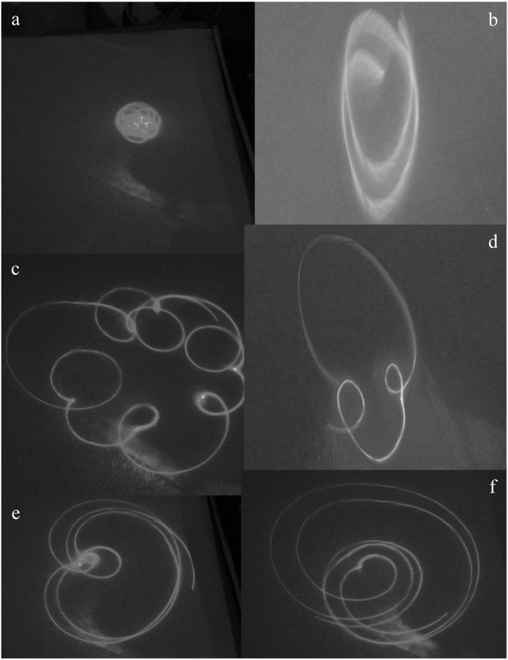
Figure 5. Laser traces obtained by reflecting a pointer beam off the Levitron surface. (a) Early undisturbed trace showing small angle precession; (b) the same after some 30 s; (c) nutational loops caused by deliberately mis-launching the Levitron or by passing a disturbing magnet in its vicinity; (d) the number of loops reduces as the Levitron slows—two loops; (e) only one loop remains not long before escape from the trap; (f) the last loop grows to almost the same size as the precessional loop, an instant before escape.
Download figure:
Standard image High-resolution image6. Precession and nutation of astronomic bodies
The third application of precession is the motion of our Earth, the Moon, space-craft and most large solid or fluid bodies in our Universe—all of which precess to some degree.
There are two types of precession: the above mentioned, standard, or slow precession, where ωp ≪ ω, and fast, free-body precession or nutation, where ωn = ωI/It.
If the Levitron is deliberately badly launched, it nutates strongly; figures 5(c)–(f) show how the number of nutational loops decreases with spin until finally only one small loop remains and grows quickly just before the spignet escapes from the trap. This is also indistinguishable from the vertical axis case.
Apart from the motion of natural bodies in space, that of artificial satellites, live or dead, is becoming an important topic. For instance, the tumbling of large pieces of space debris may make their recovery or propulsion into 'parking orbits' awkward. The same problem applies to the new asteroid mining ventures.
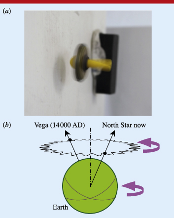
Figure 6(a) shows a spignet precessing strongly about the horizontal. Figure 6(b) is a schematic of precession and nutation of the Earth. The Earth's precession angle is 23.5° and its period is 26 000 years. In Egyptian times the 'North Star' was the faint star Thuban in Draco; the very bright star Vega in Lyra will become an acceptable North Star in 14 000 AD. The Earth nutation angles are very small 18.4'' and 13.7''. The nutation period is 18.6 years.
Figure 6. Precession and nutation: (a) picture of a heavy spignet gyrating and precessing in its superposed potential wells and (b) schematic of the Earth's motion; fast nutation oscillations overlay slow precession (not to scale).
Download figure:
Standard image High-resolution image
7. Towards HAL theory
It will be very difficult to elaborate an analytical model similar to that found in [5, 6] for the vertical axis Levitron (VAL). The reason is that whereas the VAL field lines are axisymmetric no such symmetry exists with HAL. Similarly, computation of the full precessional and nutational behaviour will be arduous. However, as with VAL, a simplified model for HAL can be initiated. Assuming that the spignet dimensions are very small, the spignet can be regarded as a point dipole. We assume that the sole function of the 'V' magnets is to create gravity cancelling lift. Both the 'V' and the outrigger fields can henceforth be ignored.
The next step is to follow what one might call the 'principle of gentle superposition'.
This principle implies that there are two levitation timescales and two space-scales. The 'micro-trap' developed by Berry and SHR operates in tens of milliseconds and over millimetre distances. The superposed 'macro-trap' operates for fractions of a second and over centimetre distances. The macro-trap displaces the centre of action of the micro-trap, allowing for inclined or horizontal axis operation. However, the macro-trap has to be gentle enough to not destroy the micro-trap. If the macro-trap gradients are too strong, the micro-trap ceases to perform. This is why the 'V', the puller, the pusher and the outrigger magnets all need to be several centimetres away from the spignet.
There are countless superposed gravitational traps in space; for example, our Moon lies in the Earth's potential well, which in turn lies in that of the Sun.
The Berry–SHR precession theory for the vertical axis Levitron can be briefly summarized as follows. With the SHR notation, the axisymmetric magnetic field is
whence the potential energy is
This leads to four important frequencies: the first frequency is the maximum spin frequency, beyond which the spignet escapes from the well,
which is of order 250 rad s−1 (ca 40 Hz); the second frequency is the precession frequency,

(ωp is of order 40 rad s−1 > ωp > 15 rad s−1) (6 and 2 Hz); the third frequency is the lower limit common to all spinning tops, but with μBo replacing mga,
of order 100 rad s−1 (16 Hz); the fourth important frequency is the bounce frequency,

ωB is the frequency with which the spignet oscillates along the axis of rotation.
There is also the above mentioned nutation frequency,

The first expression for the maximum rate of rotation does not apply to HAL since geff = 0. Also, the bounce frequency now has three components: the longitudinal, the lateral vertical and the lateral horizontal, all of order 2 Hz. The minimum, the precession and the nutation frequencies remain unchanged.
The fact that the maximum frequency depends only on the magnetic field and not g could be important for engineering applications as it means that the rotation limit could be higher.
8. HAL applications
Apart from education, HAL will have two other applications. The most immediate is in entertainment. Levitron aficionados will surely wish to try out HAL and, provided it can be simplified, it might even sell as an executive toy, complimenting existing vertical axis versions.
The second realm of application could become the most important, provided certain technical questions are resolved. Up-scaling could lead to simple near-frictionless electrical devices. If a more complex freely suspended system of two or several horizontally spinning and coupled rotors can be developed, electrical engineering applications can be envisaged: motors, alternators, flywheels and pumps. Magnetic bearings are commonplace. However, they all require either computer controlled feedback or at least one point of support. A Levitron-like horizontal axis bearing would need neither control nor support.
Down-scaling could lead to nano-technology applications. In the rapidly developing world of MEMSs (micro-electro-mechanical systems), many new mechanical components have been demonstrated. Friction is, however, a major problem. At the nanometre scale, Casimir forces come into play. If the Levitron can be scaled down far enough, a horizontal axis device could be very useful. Free magnetic suspension of a micro-rotor would be a worthwhile research project.
We have already initiated the engineering study: a large scale HAL has been developed with a neodymium spignet of greater mass; a smaller scale HAL has also been operated.
9. Conclusion
Operation of a horizontal axis Levitron is a variation on the levitation theme which could provide a new topic for university students and entertain schoolchildren. Because all Levitrons are simple analogues to space dynamics, NMR/MRI, ESR and particle trapping, the easier to operate horizontal device could be of interest to physics and engineering teachers. Some research might lead to industrial applications.
Footnotes
- *
Patent pending.
- 1
By 'Levitron' we mean the original device in which a spinning magnetic top or 'spignet' [7] is levitated above a magnetic base. We exclude all devices that have borrowed the name but rely on electromagnets, Lenz's law, diamagnetics or superconductors.
Biographies

Max Michaelis taught at the University of Natal, South Africa, for over a quarter of a century; he developed a 'laser-lab', specializing in laser applications such as atmospheric LIDARs, laser produced plasmas and gas lenses. A flame lens capable of focusing high power laser beams was also developed. In his retirement, he continues to carry out research in his home laboratory and frequently visits the Rutherford Appleton Laboratory, UK.