

Abstract
The advantage of the joule balance over the classic watt balance is that the dynamic measurement in the watt balance is replaced by a static measurement, which makes the whole measurement procedure easier. The main problems in the joule balance are the precise measurement of mutual inductance and coil heating. These problems and recent progress in the development of the joule balance are described and discussed in this paper. The whole system is at the stage of being adjusted and improved. The principle of the joule balance has been demonstrated by a measurement of the Planck constant, h = 6.626 104(59) × 10−34 J s with an 8.9 ppm measurement uncertainty.
Export citation and abstract BibTeX RIS
1. Introduction
The watt balance is one of the principal methods for the measurement of the Planck constant h [1]. A number of NMIs are participating in this programme using the same basic principles but with different approaches. A difficult problem of the watt balance is the dynamic measurement during which the coil is moving. NIM of China proposed a different approach, in which the dynamic phase is replaced by a static one [2], which makes the whole measurement procedure easier. At the same time, the power equilibrium equation of the watt balance is transformed into an energy equilibrium equation. Thus, the method proposed by NIM is named the 'joule balance'. However, in practice, there are some important difficulties that must be overcome in the joule balance method. In what follows, these difficulties, as well as some recent progress, are described.
2. The measurement principle of the joule balance
In the joule balance the following coil system is used: the exciting coil is fixed and a current Iex flows through it, and a movable coil is hung on the beam of a balance and the current through it is Imo. The electromagnetic force between the exciting coil and movable coil is (∂M/∂z)IexImo, in which M is the mutual inductance between the exciting coil and movable coil. If this force is balanced by the gravitational force of a mass m, we have following equation:

where z is the vertical coordinate. The term Δfz(z) on the right-hand side of this equation is the residual out-of-balance force of the balance.
In equation (1) the key term, i.e. the partial derivative term ∂M/∂z, is difficult to determine for a coil system. If the following method is used, however, it becomes easier. By taking an integral of both sides of equation (1) from z1 to z2 along a vertical path, we obtain
This equation is an energy balancing equation. Therefore, the method based on equation (2) is named the 'joule balance method'.
According to equation (2), the whole measurement procedure can divided into two phases.
- 1.Mutual inductance measurement.
- 2.Force measurement.
The first one is to measure mutual inductance values M(z1) and M(z2), as well as z1 and z2 precisely. The second phase is to measure the residual out-of-balance force Δfz(z) at many points in the range from z1 to z2, then the integral
 can be obtained. The residual force Δfz(z) and the integral
can be adjusted to be very small, if the homogeneity of the magnetic field in [z1, z2] along the vertical direction is good enough. Thus only two different vertical coordinates z1 and z2, as well as corresponding mutual inductance values M(z1) and M(z2), need to be measured precisely. The essential conditions are that z1 and z2 are exactly in a vertical line and that M(z1) differs from M(z2) only by the fact that it has been moved vertically a distance z2 − z1.
can be obtained. The residual force Δfz(z) and the integral
can be adjusted to be very small, if the homogeneity of the magnetic field in [z1, z2] along the vertical direction is good enough. Thus only two different vertical coordinates z1 and z2, as well as corresponding mutual inductance values M(z1) and M(z2), need to be measured precisely. The essential conditions are that z1 and z2 are exactly in a vertical line and that M(z1) differs from M(z2) only by the fact that it has been moved vertically a distance z2 − z1.
Equation (2) is the basic equation of the joule balance. From the above description, it can be seen that all measurements are carried out under static conditions, thus the measurement problem of the dynamic phase in the watt balance is avoided. The whole measurement procedure becomes easier.
3. The measurement of mutual inductance
It is obvious that the precise measurement of mutual inductance is an essential part of the joule balance method. Moreover, considering that the coils are static, it is the dc value of mutual inductance that must be measured. The practical method of measuring mutual inductance used for the joule balance is described in [4]. It can be introduced briefly as shown in figure 1. An exciting current i(t) passes through the exciting coil of the measured mutual inductance. At the beginning the exciting current i(t) has a dc value I1. Then this current increases from I1 to I2 along a sloping curve, then stops at I2. The induced voltage v(t) at the output terminals of the movable coil forms a rectangular wave. The area of this waveform is

Thus, if we can measure the area of the induced voltage waveform, the dc value of mutual inductance M can be determined.

Figure 1. Basic scheme to measure the mutual inductance.
Download figure:
Standard image High-resolution imageTo measure the waveform area more precisely, a compensation method is used as shown in figure 2. A compensation waveform having a precise area very close to that of the induced voltage waveform is generated by an electronic circuit. Only the small area difference of the two waveforms needs to be measured. The mutual inductance measurement uncertainty is thus considerably reduced to a few parts in 107 by means of this compensation method when measuring the standard mutual inductor. It is also planned that the voltage standard (Fluke 732B) used up to now in the electronic circuit generating the rectangular compensation waveform will be replaced by a programmable Josephson standard. This should reduce the measurement uncertainty drastically to a level of several parts in 108.

Figure 2. Precise measurement of mutual inductance with a compensation method.
Download figure:
Standard image High-resolution image4. The coil system
For the joule balance method, a coil system is necessary to form the mutual inductance. For this magnetic system, coil heating is a problem to be considered. At a first glance, using a superconducting coil would be helpful in reducing the coil heating. However, the Meissner effect of superconducting leads will cause a troublesome measurement uncertainty, because the magnetic status is different between the weighing phase and the mutual inductance measurement phase. In the first phase the movable coil hanging on the balance beam has a current flowing through it to produce the magnetic force, but in the second phase no current is flowing in this coil, only the induced voltage at its terminals is measured. Thus, the current distribution in the fixed superconducting coil will be changed due to the Meissner effect when the measurement procedure changes from one phase to another. Some systematic error will be present that is difficult to evaluate precisely.
Other ways are also possible for reducing the measurement error due to coil heating. One of them is to optimize the coil design to get a higher magnetic field with the same coil current. For example, decreasing the distance from the exciting coil to the movable coil is an effective way. Calculation shows that a more compact design could reduce the coil heating power to 1/3 compared with the original. This conclusion is confirmed by a practical coil system shown in figure 3. A disadvantage of this configuration is that the vertical position of the outer movable coil is limited by the inner exciting coils. The maximum movement range is ±2 cm. The installation of coils is also inconvenient.
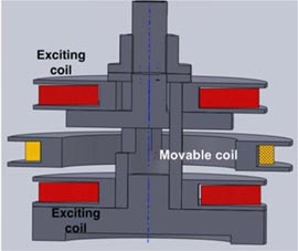
Figure 3. Compact coil system.
Download figure:
Standard image High-resolution imageAnother method to decrease the coil heating effect is based on the following consideration. In fact, the effect of heating on the force is different for the inner and outer coils. The diameter of the coils is increased due to the current heating. The expansion of the inner exciting coil reduces the distance between the inner and outer coils and the force between them will become stronger. However, the expansion of the outer coil increases this distance and the force becomes weaker. The effect of these two kinds of deformation is thus to cancel out the errors and only the residual effect is to be considered. Therefore, by changing the current ratio in both coils, the cancelling of two opposite errors can be optimized so that the force becomes almost invariant with coil heating.
However, on the other hand, a more precise geometry requirement for the compact coil system should be considered. For a compact coil system, a small dimensional error of the practical coil can lead to an obvious deviation of the force curve from ideal as shown in figure 4. In contrast, the calculated force curve of the ideal coils, for which the exciting coils are perfectly symmetrical, and the measured curve for the practical coils have a slight difference. A further analysis shows that this kind of deviation mainly originates from some slight asymmetry between the upper and lower exciting coils.
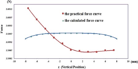
Figure 4. Magnetic force curve of exciting coils with slight asymmetry.
Download figure:
Standard image High-resolution imageFurther improving the coil dimension is not easy because it is difficult to form a very precise coil. A better and easier approach to decrease the deviation of the practical curve from the ideal is using a compensation coil. The force curve of a compensation coil with only a few turns is shown in figure 5(a) and the total force curve after compensation becomes much better as shown in figure 5(b). From figure 5 it is seen that the compensation coil improves the force and makes it more uniform.
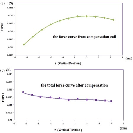
Figure 5. Effect of a compensation coil.
Download figure:
Standard image High-resolution imageTo decrease the coil heating further, a system using ferromagnetic material to decrease the magnetic resistance is also designed. In this new system, the magnetic path is mainly in the ferromagnetic material and the magnetic field in the gap, in which the movable coil located, is much stronger by a factor of five. At the same time, the coil heating power is reduced to 1/5 (about 7 W). The range of distance moved is also enlarged from 2 cm to 10 cm. Thus, the uncertainty from distance measurement could also be reduced. However, for such a system, the non-linear effect from the ferromagnetic materials should be calculated carefully.
5. The balance and coil position changing
The balance is another essential part for this project. In the first design, the coil is moved by tilting the balance beam as shown in figure 6.
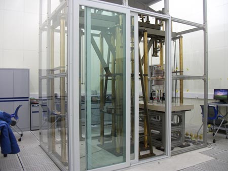
Figure 6. Balance with 2 m beam.
Download figure:
Standard image High-resolution imageThe total length of the beam is about 2 m to reduce the departure of the coil movement from the vertical. However, it is found that a tilting beam is not suitable for the force measurement due to the knife deformation during the beam tilting as shown in figure 7. This kind of deformation is not very stable and difficult to evaluate exactly. At the same time, equation (2) shows that the force measurement at different vertical positions is important to get the term
for the joule balance method. It seems better to leave the coil suspended from the balance beam untouched and to change the vertical position of the exciting coils, which are the inner coils as shown in figure 3. For this purpose, an adjustable supporting platform for the exciting coil has been designed as shown in figure 8. This supporting platform can change the vertical position of the exciting coils over a range of 2 cm. Thus, the force measurement at different vertical positions of the coil becomes easier.
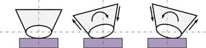
Figure 7. Knife deformation when the balance beam is tilting.
Download figure:
Standard image High-resolution image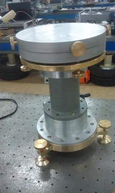
Figure 8. Adjustable supporting platform for the exciting coil.
Download figure:
Standard image High-resolution imageAnother problem found in the experiment is that, even when the position of the coil suspended from the balance beam remains untouched during a measurement, the practical coil position is still not very stable and a random variation in coil position of about 1 µm due to the ground base vibration and air flow is observed. To decrease this kind of perturbation, an oil damping device has been installed on the movable coil as shown in figure 9. For this kind of damping device, a buoy is immersed into oil in a cup. The buoy is formed by a pleated plastic film with necessary rigidity and is suspended by two thin rods. When this buoy moves in any direction, enough damping force will be produced. The experiment showed that the coil swing is attenuated to an undetectable level after 1 min to 2 min. The reproducibility of measurement results of the mutual inductance is improved.
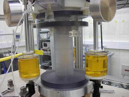
Figure 9. Damping devices installed on the movable coil.
Download figure:
Standard image High-resolution imageFurthermore, a laser locking system including a piezoelectric crystal device is used for the coil. It considerably reduces the random variation in coil position, as shown in figures 10 and 11.

Figure 10. Vertical position locking of the movable coil.
Download figure:
Standard image High-resolution image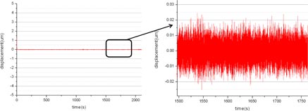
Figure 11. Curve after locking in detail.
Download figure:
Standard image High-resolution image
6. The experimental result
Although the adjustment of the whole system is still in progress, a determination of the Planck constant h has been made to check the principle of the joule balance.
In 2013, after the improvements mentioned above, the value of the Planck constant obtained is

The experimental relative uncertainty is about 8.9 × 10⁻⁶, mainly from the reproducibility of the experimental result. The reproducibility problem is due to the unfavourable disturbance of the coil heating on the mutual inductance measurement. The term ∂M/∂z in equation (1) is almost a constant in [z1, z2], thus the value of M(z1) or M(z2) is strongly dependent on the position z1 or z2 (according to a linear relation). As a result of the coil heating, the frame and supporting rod of the exciting coils expand during the measurement. Thus z1 or z2, as well as the value of M(z1) or M(z2), is changing over time. On the other hand, the mutual inductances M(z1) and M(z2) in equation (2) are measured at z1 and z2, respectively. These two measurements cannot be carried out at the same time. Therefore, the values z1, M(z1) and z2, M(z2) used in equation (2) refer to different moments, thus a rather bad reproducibility of the experimental results appears. It seems that some important improvements to the equipment are still necessary.
7. Improvements planned for future work
The first apparatus embodying the joule balance principle has been completed and many problems have been found and solved as described above. The next generation apparatus is being designed in 2014. The main improvements will be as follows.
- (1)A coil system with ferromagnetic core is being built. At first glance, it is similar to the ones in other NMIs, but for the joule balance this will not include a permanent magnet; the necessary magnetic field will still be generated by coils. The advantages of this new coil system will be a stronger magnetic field and less coil heating.
- (2)The balance with a long beam will be replaced by a mass-comparator with 1 µg sensitivity and 5 kg range.
- (3)A new apparatus for measuring the mutual inductance of the coil having a ferromagnetic core is also to be developed. The non-linear effect and eddy current in the ferromagnetic materials should be calculated carefully.
8. Conclusions
An apparatus with the same purpose but using a different working principle from the watt balance—a 'joule balance'—has been developed in NIM of China. The working principle and initial problems encountered, as well as the recent improvements, are described. The principle of the joule balance has been demonstrated by a measurement of the Planck constant with an uncertainty of 8.9 ppm. Plans are underway to make significant improvements based on the experience now gained.
Acknowledgments
The authors thank Dr Quinn for his continuous encouragement during the development of the joule balance method.