
Abstract
Flow batteries represent a possible grid-scale energy storage solution, having many advantages such as scalability, separation of power and energy capabilities, and simple operation. However, they can suffer from degradation during operation and the characteristics of the felt electrodes are little understood in terms of wetting, compression and pressure drops. Presented here is the design of a miniature flow cell that allows the use of x-ray computed tomography (CT) to study carbon felt materials in situ and operando, in both lab-based and synchrotron CT. Through application of the bespoke cell it is possible to observe felt fibres, electrolyte and pore phases and therefore enables non-destructive characterisation of an array of microstructural parameters during the operation of flow batteries. Furthermore, we expect this design can be readily adapted to the study of other electrochemical systems.
Export citation and abstract BibTeX RIS

Original content from this work may be used under the terms of the Creative Commons Attribution 3.0 licence. Any further distribution of this work must maintain attribution to the author(s) and the title of the work, journal citation and DOI.
Introduction
Redox flow batteries (RFBs) are seen as a promising technology for grid-scale storage, given their rapid reversibility and separation of power and energy capacities [1–7]. Many different flow battery chemistries exist or have been proposed, but one of the most promising is the all-vanadium flow battery, or VRFB [8, 9], a schematic of which is shown in figure 1. Despite not employing complicated solid state electrodes as in lithium ion batteries they still suffer from little-understood degradation issues stemming from the corrosion of the commonly used carbon felts at high voltages in acidic environments. In addition, the wetting and compression of the carbon felts and their effect on performance of RFBs is poorly understood, with a range of felt modifications also presented in the literature [10–23].

Figure 1. A schematic of a VRFB showing two tanks containing electrolyte with electroactive vanadium species, the positive and negative electrodes (usually carbon felts) and the proton conducting membrane. The power of the battery is dictated by the size of the electrodes, while the energy storage is decoupled and dependant on the size of the electrolyte tanks. In charging mode V(IV) is oxidised to V(V) at the positive electrode and V(III) is reduced to V(II) at the negative electrode. The reactions are reversed for discharge.
Download figure:
Standard image High-resolution imageIn situ and operando x-ray imaging techniques have been used to great effect to study microstructural changes in energy devices such as lithium ion batteries, summarised in a recent review by Weker and Toney [24], solid oxide fuel cells [25–32], and polymer electrolyte membrane fuel cells and electrolysers [33–36]. The unique non-destructive nature of x-ray imaging allows characterisation of energy materials under different operating conditions and stages of cycle lifetime, as well as extraction of useful parameters for modelling, such as porosity, tortuosity, surface area, and shape and size of electrode particles—changes in which can be followed in 3D by using increasingly rapid acquisition of x-ray tomographic data with synchrotron radiation sources [37–41]. Lab-based x-ray imaging techniques can offer high spatial resolution, comparable with synchrotron imaging; however, due to significantly lower photon flux they have lower temporal resolution, meaning that it is often not possible to study dynamics or transient phenomena associated with normal operation. Nevertheless, the advantages of lab-based x-ray CT are often underestimated—namely, ease of use, accessibility, lower cost and potentially large scanning areas—and it can be a highly effective complementary tool to synchrotron imaging [42].
Recently, the potential of x-ray imaging as a diagnostic tool for corrosion of carbon felts has been demonstrated [43]: the results showed visible damage and agglomeration of the carbon fibres relatively early on in the charge–discharge cycle of the RFBs. Combination of the tomography data with image based modelling revealed the microscopic transport properties of the felt. However, the micro-CT was conducted ex situ on felts that had been removed from the operating environment. Particularly for wetting and compression effects, in situ imaging at large working distances of operating RFBs would provide valuable insight into the processes that change the porosity of the felts as charging or discharging proceeds. Given the hydrophobic nature of the felts and that the performance of RFBs is intrinsically linked to the surface area available for reaction, the proportion of the pores filled with electrolyte is a vital metric in assessing the quality of different carbon felts, and at different compressions [19, 20]. In addition, calculation of porosity and tortuosity of the felt materials allows an understanding of the transport properties of the electrolyte through the electrodes, a vital factor in the amount of parasitic pumping power required in the whole system and affecting balance of plant component design [44, 45].
This paper presents the design of a miniature flow cell with rotational symmetry, suitable for operando x-ray imaging in both synchrotron and lab CT setups, allowing real-time imaging in three dimensions of electrolyte ingression at varying compressions, calculation of wetting and saturation parameters, and assessment of the changes in the material properties upon degradation. Such a device enables the coupling of electrochemical performance with microstructural evolution and could provide vital insight into the causes and effects of electrode degradation in flow cells. Details of the design of such a cell are presented, as well as initial imaging using both synchrotron and lab sources demonstrating the potential of x-ray CT as a tool for evaluation of performance of flow batteries and electrode materials.
For the first time, we show the capability for imaging of flow battery carbon felt materials with electrolyte intrusion in a bespoke cell designed for in situ and operando x-ray tomographic imaging. The spatial and temporal resolution achievable in lab-based and synchrotron tomography allows vital properties of a flow cell to be studied in situ and operando under various operating conditions using such a cell.
Methods
Cell design
Most flow cell designs incorporate a square planar geometry, with two carbon felt or carbon paper electrodes separated by an ion conductive membrane, and metallic or graphite current collection plates, all held under compression by metallic end plates with bolts or tie rods. Peripheral pumps deliver electrolyte from tanks to the electrodes, through the endplates, via tubing. Various typical designs are discussed in the review by Alotto et al [46] and a schematic of a typical stack is shown in figure 2. The materials used in these cells are highly attenuating to x-rays and therefore a new design of cell is required to allow imaging of a flow battery. During collection of tomography data, a sample is rotated through 180–360° relative to an x-ray source and detector, with projection images collected at discrete angular steps. These projection images can be reconstructed using back-projection algorithms to form a 3D volume [47]. To maximise data quality, the primary concern in cell design is to incorporate rotational symmetry in the region of interest for imaging. This reduces the artefacts produced on reconstruction of the 3D image from the 2D projections and allows the attenuation of the beam to be constant at all angles. Thus, the electrodes, membrane and current collectors all take the form of disks, contrary to the square designs more commonly seen in flow cells. Additionally, flexible tubing that connects to the cell is allowed to wrap around the body of the cell, ensuring that the electrolyte can be delivered without being in the field of view of the imaging.
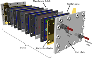
Figure 2. Exploded view of a typical flow battery stack with a square geometry and many metallic components with high x-ray attenuation, making it unsuitable for x-ray CT investigations.
Download figure:
Standard image High-resolution imageThe cell is constructed from polypropylene to maximise transmission of x-rays whilst providing chemical resistance to the 3 M sulphuric acid used in the electrolyte of vanadium RFBs. The wall thickness of the cell is minimised in order to reduce x-ray attenuation while maintaining mechanical strength. The diameter of the electrode volume was selected to be 11 mm, a compromise between a size that is small enough to be included in the full region of interest of a CT scan and large enough that the volume is representative of the behaviour of a larger volume used in the majority of flow batteries. Adjustable pistons containing channels for delivery and removal of electrolyte, as well as a channel for a current collector wire, allow the compression of the electrodes to be controlled (figures 3(a) and (b)). The range of movement of the pistons allows felts of up to 1.2 cm thickness to be used in the cell. Currently, the design does not incorporate flow field channels but can easily be adapted for future studies into the effect of flow field design on electrolyte intrusion and distribution. In the design and configuration outlined in this work, electrolyte is delivered to the surface of the felt through one of the channels in the piston, flows through the felt to a second channel in the piston where it exits the electrode volume. Aluminium spacer disks allow the compression to be controlled accurately and consistently between experiments, and the assembly of the cell is swift and trivial with aluminium tie rods providing overall compression. The compression provided by the pitons is even and aids in the prevention of flow of the electrolyte around the edges of the felt, and is easily adjustable allowing for the study of electrolyte flow behaviour under various compressions. Separation of the electrolyte between the two electrodes is achieved by clamping the membrane (with two PTFE ring gaskets) onto a shelf in the main central body of the cell (figure 3(d), red) using a second internal piece (figure 3(d), blue), and two Viton o-rings on the adjustable pistons prevent electrolyte leakage via the outside of the piston. Manufacturing of the cell was carried out by GGM Engineering (Middlesex, UK). The felts used in this study are SIGRACELL GFD graphite felts (SGL Group, Germany) that have been heat treated in air at 400 °C for 30 h in air in order to thermally oxidise the surface of the fibres, as is often done in RFBs to increase the hydrophilicity [48].
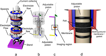
Figure 3. Design of the mini flow cell (a), with transparent view showing internal workings of the cell (b). The path of electrolyte and working part of the cell (membrane, felt electrodes and current collection) is shown in (c), and (d) shows a detailed view of the imaging region, including the sealing that separates the two electrodes achieved by clamping the internal body (blue) onto a shelf created in the external body of the cell (red). O-rings prevent electrolyte from flowing through the gap between the internal body and the adjustable piston.
Download figure:
Standard image High-resolution imageLab-based x-ray CT
Prior to synchrotron experiments ex situ imaging of felts was conducted using a lab-based micro-CT machine (Zeiss Xradia Versa 520, Carl Zeiss XRM, Pleasanton, CA), operating with a source voltage of 40 kV. Imaging of the flow cell was conducted in the same manner, except with a source voltage of 80 kV to take into account the higher attenuation of the cell housing and longer absorption path of the x-rays. The number of projections and exposure time in each scan differed in order to obtain sufficient counts for each image and the details are given in the relevant image captions. Electrolyte consisting of 3 M sulphuric acid and 1.6 M vanadium (III/IV) species was pumped through the cell before the tubes were clamped and the cell was imaged containing a static volume of electrolyte. The experimental setup is shown in figure 4.

Figure 4. Miniature flow cell containing static electrolyte in the lab-based x-ray CT system. The source (on the left of the image) and detector (on the right of the image) are brought as close as possible to the cell during imaging to improve the quality of the scan. Inset shows the cell in more detail.
Download figure:
Standard image High-resolution imageSynchrotron x-ray CT
Following characterisation of the cell using lab based CT, imaging of the flow cell was also carried out at the TOMCAT beamline of the Swiss Light Source synchrotron [49], which owing to the vastly improved x-ray flux allowed for much quicker acquisition times. These tomograms were collected using 1801 projections over a 180° rotation with 333 ms exposure time each, with a parallel monochromatic beam at 25 keV. A 10× optical magnification was employed, giving a pixel size of 0.65 µm, and radiographs were captured using a lutetium aluminium garnet:cerium (LAG:Ce) Scintillator and PCO.Edge 5.5 camera. Tomograms were reconstructed using the Gridrec algorithm [50], and in some cases Paganin reconstruction was used to enhance the contrast between phases [51].
Results and discussion
Figure 5 shows the x-ray CT of the flow cell containing electrolyte. Virtual slices can be taken through the reconstructed data at any point and angle, and show a good contrast between electrolyte, metal, air and the polypropylene cell housing (figure 5(a)), allowing separation and visualisation of component materials, this has been achieved using Avizo Fire software (FEI VSG, Mérignac Cedex France) (figure 5(b)) which allows the cell to be viewed at any angle and with any part of the cell removed/displayed.
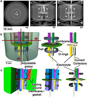
Figure 5. X-ray CT image of the flow cell containing static electrolyte: (a) three orthoslices of the reconstructed volume along the xy, xz and yz planes, (b) segmented image created using Avizo software allowing separation of the separate pieces and materials of the cell (labelled) and showing the position of the xy and yz orthoslices taken in (a) (red lines, xz is in the plane of the image), (c) a virtual cut into the cell allowing visualisation of the inner sections of the flow cell. The scan was conducted on a lab based CT system with 0.4× detector (effective pixel size of 31 µm) and comprised 3201 projections with an exposure of 10 s each. Comparison with figure 3 shows the components that make up the cell.
Download figure:
Standard image High-resolution imageThe metal tie rods used to compress the cell cause significant artefacts due to the high x-ray attenuation of the material causing areas of low transmission, and hence a lack of information that is required in the mathematics of the reconstruction. This can be seen at the vertical extremes of the xz and yz orthoslices in figure 5(a), and so the volume was cropped to allow easier segmentation of the more relevant central region of the cell. As well as viewing specific parts of the cell at any angle, it is also possible make virtual cuts into the reconstructed volume and view the internal parts of the image (figure 5(c)).
In order to ascertain the quality of scans possible in situ in this cell design, ex situ scans of fresh felt were collected on the lab-based CT system (figure 6). By using a high number of projections and minimising the amount of sample outside of the region of interest it is possible to obtain very good quality, high resolution images of the felts. The segmented image could then be used in structure-based modelling to determine parameters such as pressure drop through the felt, transport phenomena and local reactant concentrations [45, 52]. The high quality of the imaging is due in part to there being no extra material surrounding the felt, and therefore minimal artefacts and good transmission of x-rays through the sample.
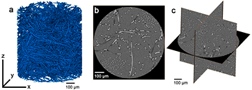
Figure 6. Ex situ felt scans obtained using a lab-based CT system with 3201 projections of 15 s exposure using a 20× optical magnification, resulting in a pixel size of 0.80 µm: (a) a 3D reconstruction of the scan showing felt fibres (blue) and air pores (transparent), (b) an xy orthoslice of the same volume and (c) three orthogonal orthoslices of the felt in the xy, yz and xz planes.
Download figure:
Standard image High-resolution imageConversely, figure 7 shows an in situ scan of the flow cell at a higher magnification, using a 4× objective lens to achieve an isotropic voxel size of 3.8 µm—high enough resolution to resolve the fibres of the felt volume. The image highlights an area of the electrode that contains incomplete wetting of the felt by electrolyte. From the orthoslice (figure 7(a)) it is possible to differentiate the fibres of the felt from the areas of vanadium electrolyte, and therefore segment the image into the current collector, felt and electrolyte materials (figures 7(b) and (c)). Comparison with the ex situ felt scans in figure 6 shows the complications of including extra material outside the region of interest and the subsequent influence it has on the resulting image quality. Nevertheless, the miniature flow cell shows the possibility of assessing the degree of wetting of the felts, under differing conditions of compression, flowrate and with different felt types. Incomplete wetting of the felts not only reduces the active volume available for the redox reactions to take place in (and hence introducing mass transport overpotentials and subsequent voltage inefficiencies), but may cause areas of local fluctuation in electrolyte concentration and high potentials as the electrode is starved of reactants [52]. This could lead to accelerated degradation of felt materials and unwanted side reactions, such as hydrogen evolution, that could reduce the lifetime and efficiency of the flow battery. The miniature flow cell also has the potential for operando imaging, which would allow investigation of bubble formation and possibly degradation of the electrode materials in real time, particularly when using a synchrotron x-ray source where the higher photon flux would allow rapid acquisition of tomograms.

Figure 7. X-ray CT imaging of the flow cell containing static electrolyte obtained using a lab-based CT system with a 4× objective lens (effective pixel size of 3.8 µm) comprising 1601 projections of 7 s exposure. Areas of incomplete wetting of the felt can be seen in the orthoslice (a) and segmentation of the Ti current collector (grey), felt (red) and felt containing electrolyte (purple) is possible (b). The electrolyte volume has been removed in image (c) and a Ti mesh current collector was employed in this instance.
Download figure:
Standard image High-resolution imageFigure 8 shows images of the electrode area of the flow cell containing electrolyte fully wetting the felt volume obtained using a synchrotron radiation source. In this case, the tomograms show improved signal-to-noise ratio than those obtained in the lab CT scan (figure 7) and allow for easier segmentation of the fibres from the electrolyte phase (figure 8(c)). The high flux of the synchrotron source also has the benefit of much reduced scan times; in this case 10 min compared to 3 h for each tomogram which will allow much more wide-ranging studies of felt wetting and electrolyte ingression at varying flow rates, compressions and felt types to be conducted in reasonable time scales. Conversely, despite the long acquisition times for lab-based CT scans, the accessibility of the facility allows for much longer-range experiments where the state of the battery can be periodically examined throughout the course of many charge–discharge cycles. This can be done by pausing operation, scanning the cell in situ (but not operando) and then returning the cell to operation—all of which can be done without disassembling the cell and, therefore, changing the operating conditions. Usually, access to a synchrotron radiation source is limited to a short, finite period of time, during which it might not be possible to study the cell over many charge–discharge cycles, despite the rapid acquisition time, as the rate determining step becomes the length of time the battery takes to charge. Figure 9 shows an example of a felt with incomplete wetting, leading to pockets of empty pores, as well as areas of electrolyte wetted fibres. The contrast between these pores and the electrolyte is enhanced in figure 9(b) and (c) by employing a Paganin reconstruction [51] to improve phase contrast and ease of segmentation enabling calculation of wetting amounts, pore size distribution and contact angles, amongst other metrics. However in figure 9 the electrolyte and felt phases are difficult to distinguish due to their similar attenuation coefficients, though this could be improved in the future with changes to the image acquisition or by the adoption of a composite absorption and phase contrast imaging methodology [53]. Characterisation of wetting amount and gas pore size and distribution could provide vital insight into the operation of flow batteries.
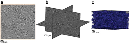
Figure 8. In situ felt scans obtained using a synchrotron light source, containing static electrolyte. (a) Orthoslice showing good contrast between fibre and electrolyte phases, (b) orthogonal orthoslices showing, in this case, a complete wetting of the felt with no areas of gas filled pores, and (c) a 3D reconstruction of the scan volume showing separation of fibres (blue) and electrolyte volume (transparent).
Download figure:
Standard image High-resolution image
Figure 9. In situ felt scans obtained using a synchrotron light source, showing areas of gas filled pores in the static electrolyte (a). Paganin reconstruction [51] has been used in (b) and (c) to enhance the contrast between the pore volume and the wetted areas of the felt.
Download figure:
Standard image High-resolution image
It is therefore proposed that a miniature flow cell, such as the one described in this work, could have the potential for investigation into the operating properties of flow batteries and degradation of electrode materials in a non-destructive manner, not possible with other characterisation methods. We expect that in situ and operando tomography of flow batteries will provide vital insights into the behaviour, causes of performance loss and degradation of these devices, with the aim of increasing performance and improving the material properties of their components.
Conclusions
A miniature flow cell incorporating rotational symmetry and allowing variable compression of electrodes was designed and constructed from polypropylene. X-ray tomography has shown that it is possible to image the electrodes in three dimensions and segregate the carbon felt material, vanadium electrolyte and air phases. The cell design shows promise for operando tomography of RFBs and could incorporate many different chemistries or even different electrochemical systems, such as microbial fuel cells. X-ray CT characterisation of flow batteries and the materials used in the devices could provide vital information about their operation and degradation, as well as enabling improvement in performance and durability.
Acknowledgments
The authors thank the UK EPSRC for funding (under the grants EP/L014289/1, EP/N032888/1), and from an EPSRC 'Frontier Engineering' Award (EP/K038656/1). PRS acknowledges the Royal Academy of Engineering for funding. Synchrotron imaging experiments were performed on the TOMCAT beamline at the Swiss Light Source, Paul Scherrer Institut, Villigen, Switzerland and we acknowledge the beam line staff, in particular Dr David Haberthür for their contribution. The authors also thank GGM Engineering for valuable discussion on the design and manufacturing of the cell.