


ABSTRACT
The coronagraphic imaging of nearby solar systems with a densely packed array of small, inexpensive collector telescopes is considered. A reduced-scale segmented pupil can be assembled downstream of the collectors either by means of an array of delay lines, or more conveniently, by means of an array of single-mode fibers. In either case, the individual pupil elements are completely decoupled from each other. Tuning the intensity and phase of the light in each pupil element then allows complete control over the pupil-plane field, thus enabling arbitrary and tunable complex pupil-plane apodization. Calculations show that such a "phased-array coronagraph" (PAC) can in principle provide the10−10 image-plane contrast required for terrestrial exoplanet observations near bright stars. A PAC may thus provide a route to coronagraphic observations of faint exoplanets that is both flexible and potentially relatively inexpensive.
Export citation and abstract BibTeX RIS
1. INTRODUCTION
The imaging of faint exoplanets very close to much brighter stars requires the development of very high contrast, narrow-field imaging techniques. A number of novel coronagraphs have recently been proposed in this regard (e.g., Guyon et al 2006; Cash 2006), and observational (Marois et al. 2008) and laboratory (Trauger & Traub 2006) coronagraphic performance is steadily improving, but the performance needed to image extrasolar planets as much as 10 orders of magnitude fainter than their host stars remains extremely challenging, both technically and financially. Thus, even more novel types of telescope/coronagraph architecture may be called for, especially if the cost of an exoplanet space mission is to be constrained.
To image faint exoplanets near bright stars, a small inner working angle (IWA) is required, since at a distance of e.g., 10 pc, 1 AU subtends an angle of only 100 mas. In terms of the wavelength, λ, and aperture diameter, D, the FWHM angular resolution (θFWHM) of a circular telescope aperture is ≈ λ/D, or, with λμm the wavelength in μm and Dm the aperture diameter in meters, θFWHM ≈ 200 λμm/Dm mas. Thus, for θFWHM ≈ 100 mas, Dm ≈ 2λμm, so that for the primary waveband of interest for reflected light observations, λ ≈ 0.5 to 1.5 μm (e.g., Des Marais et al. 2002), diameters of ≈ 1 to 3 m would seemingly be adequate for observations of exoplanets near the closest stars. However, because coronagraphs typically provide good transmission only beyond an IWA of a few (e.g., 1–4) λ/D of the star (e.g., Guyon et al. 2006), aperture sizes must be scaled up accordingly, resulting in telescope apertures of order several meters to reach close planets around a significant number of stars. In the case of space-based telescopes, such sizable apertures remain a challenge, especially given the high surface accuracies of order 0.1 nm (Trauger et al. 2007) required to discern Earth-equivalents reflecting ∼10−10 of the stellar flux. Indeed, all coronagraphic starlight suppression techniques are limited by the achievable wave front quality (Malbet et al. 1995), which may well exclude observations of contrasts of ∼ 10−10 through our own atmosphere. The detection of terrestrial exoplanets thus seemingly calls for large, very well corrected, and potentially very expensive space telescopes. As a lower cost alternative would be highly desirable, this paper considers a potential approach.
2. THE CONCEPT
While telescopes have long been central to astronomy, specific telescope implementations have also evolved repeatedly to meet different requirements: e.g., reflectors long ago replaced refractors to provide broadband performance, Schmidt and Ritchey–Chretien telescopes regularly supplant Cassegrain and Gregorian single-point imaging solutions for wide-field imaging (e.g., Schroeder 1987), and for extremely high angular resolution, interferometry between separated apertures comes to the fore. The case of imaging faint companions near bright stars brings its own particular requirements: specifically, high-contrast imaging over a very narrow field of view (FOV). Thus, unlike the normal imaging case, a wide FOV is not a requirement. However, in order to allow for good control of scattered starlight, and therefore for deep starlight rejection, a nearly perfectly planar (to ∼ λ/10,000; Trauger et al. 2007) stellar wave front is required. However, this nearly perfect wave front is needed specifically at the entrance to the "coronagraph," and not necessarily everywhere in the optical beam train.
To provide such an exquisitely flat wave front, there is little doubt that some type of adaptive optics (AO) wave front correction will be necessary prior to any potential coronagraph. This has two immediate implications. First, the Fourier transform relationship between the image and pupil planes implies that a pupil-plane deformable mirror (DM) with a finite number of elements can only provide a well corrected image-plane "dark hole" region optimized for exoplanet observations of finite extent (Malbet et al. 1995). Specifically, for a DM consisting of N × N elements, the maximum angular extent of the dark hole is Nλ/D × Nλ/D. Thus, rather than the telescope itself, it is the size of the DM that sets the maximum size of the FOV useful for faint companion imaging. Specifically, the "outer working angle" set by the DM's domain of influence, OWADM, is equal to half the DM's well corrected FOV. However, a limited OWA is fully acceptable in the case of exoplanet imaging, as the target field of interest for terrestrial exoplanet observations, FOVep, is also small, no more than a few arcsec. Thus, whether or not the telescope itself provides a larger FOV is largely irrelevant, since both FOVep and FOVDM are tiny. Second, with wave front correction necessary in any case, highly accurate collecting optics may be overkill. Specifically, rather than attempting to maintain a nearly perfect wave front through the entire optical train, why not aim instead at generating a nearly perfect wave front only where it is needed, i.e., at the coronagraph entrance plane? In principle one can then even consider using some type of "generalized AO system" to assemble a nearly perfect planar wave front spanning an "envelope" pupil from a set of constituent wave front "elements" at the coronagraph entrance plane. What is then needed is simply a way to collect an array of M × M independent samples of the pupil for assembly by the generalized AO system. A classical monolithic or segmented telescope could, of course, still be used to collect the desired wave front elements, but it is not required. On the other hand, one could consider gathering the M × M array of wave front elements using a pupil which is truly segmented right from the start: i.e., a pupil defined by a densely packed M × M array of small "collector telescopes," each of which collects the light in one element of the envelope pupil (Figure 1). Of course, some sort of relay optics must then be employed to assemble and phase a demagnified version of the envelope pupil somewhere downstream of the collector array for use in the subsequent coronagraph.
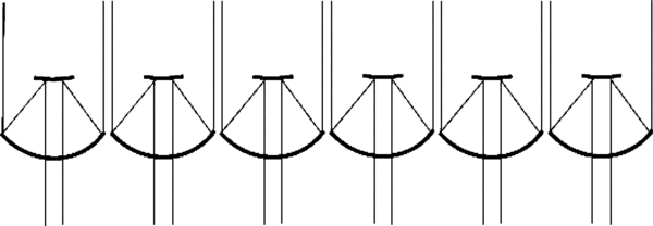
Figure 1. Conceptual layout of a MAT composed of a close-packed array of small collectors. For simplicity, only a one-dimensional cross section of the two-dimensional array is shown.
Download figure:
Standard image High-resolution imageSuch a multiaperture telescope (MAT) approach clearly eliminates the cost of a large, highly precise monolithic or segmented telescope, while introducing the costs of the M × M array of small collectors, plus any additional system integration costs. As is discussed below, very inexpensive collectors can be employed, while the coalignment and phasing systems for a close-packed MAT array may to some extent resemble typical coronagraphic wave front sensing and control systems, suggesting that the cost trade would be beneficial. The basic idea is then to substitute a MAT array for a large, highly accurate telescope in the hope of lowering overall costs.
Note that a MAT eliminates not only the primary mirror, but also the distant secondary mirror, since each individual collector can have a much shorter focal length. Thus, a MAT array is potentially much more compact than a large telescope—with small collector telescopes of diameter d filling a larger envelope pupil of diameter D, the optical assembly is a relatively flat, nearly two-dimensional structure, with a much smaller height and volume (and potentially weight) than the equivalent monolithic telescope. Indeed, assuming similar primary focal ratios for the large telescope case and the individual MAT collectors, the MAT assembly height (along the observation direction) can be smaller by d/D, potentially a very significant reduction.
As mentioned, a MAT-based approach requires a means of assembling and phasing the M × M "beamlets" from the array of collector elements into a demagnified version of the envelope pupil. The "phasing" across a monolithic telescope aperture is normally provided by the telescope surface itself, along with a subsequent DM when high accuracy is needed. However, for a MAT, optical path difference (OPD) matching between the beamlets filling the envelope pupil needs to be achieved in some other fashion. Moreover, the individual beamlets must also be compressed laterally so as to provide a scaled, demagnified pupil. Lateral compression is normally also provided directly by the monolithic telescope itself, but in the MAT case, while each beamlet diameter is reduced by its collector telescope, the beam spacings must still be demagnified appropriately.
Thus, to phase and compress the downstream pupil, an M2-element optical relay is needed. One can consider using a set of M2 optical delay lines (Figure 2), but this approach becomes more cumbersome as the number of collector telescopes grows. Alternatively, one could simplify the optical transport to the reduced pupil by means of an array of single-mode (SM) fibers, with an individual SM fiber coupled to each collector (Figure 2). There are of course differences between the two approaches. First, because SM fibers couple only to light within an SM, the fibers set an outer working angle (OWAf) on the sky of ≈λ/2d, beyond which sources are largely inaccessible to observation. Second, a fiber-based relay may allow for very simple single-element collector telescopes (e.g., off-axis paraboloids), because small focal-ratio primary collector mirrors could directly provide good coupling to fibers. Finally, the fibers do not transport an image in the classical, ray-based sense. Instead, since each fiber carries only light in a single mode (so that within a fiber, all light propagates in the same direction), the arrival direction of the light (for an off-axis angle within the fibers' FOV) is encoded within the fiber array by means of the relative phases between the fibers (Mennesson et al. 2003). Imaging through an array of SM fibers thus remains possible. Since for a given source direction, each SM fiber transmits the average phase present within that collector's input beam, the sampling of an off-axis source's linear phase gradient leads in the ideal case to a "staircase" phase distribution at the output of the fiber array (Figure 3). As with a grating, the image lies at the angle for which constructive interference between the phase steps occurs, i.e., in the original image direction. Thus within the fiber's SM FOV, the imaging remains true even after passage through the fiber array.
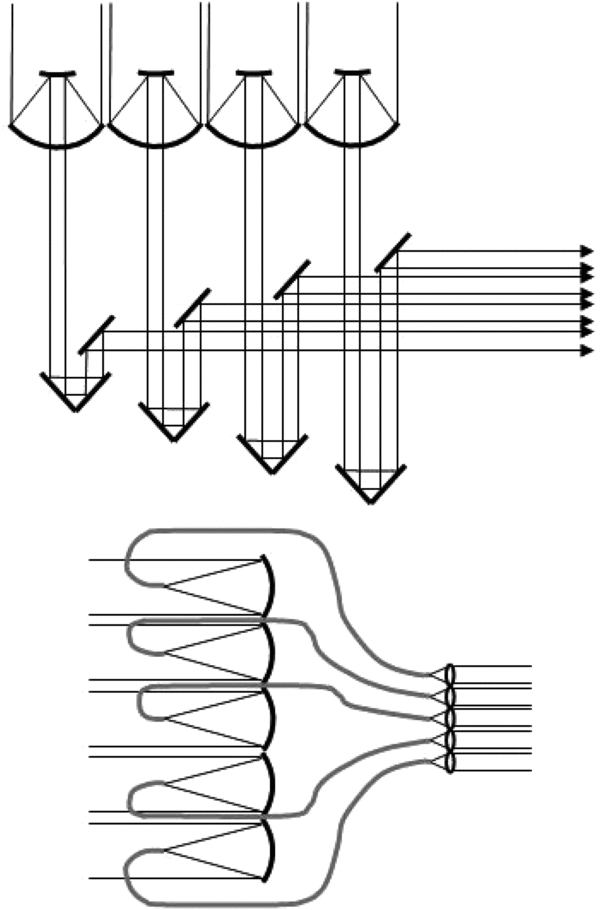
Figure 2. Examples of MAT relay optics. Top: a delay-line based relay. Bottom: a single-mode-fiber based relay.
Download figure:
Standard image High-resolution image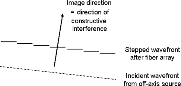
Figure 3. Schematic showing the imaging of an off-axis source with a fiber array.
Download figure:
Standard image High-resolution imageIn the case of a fiber relay, both the DM and the fiber's SM FOV limit the size of the FOV. A fiber-based relay is thus optimized by setting OWAf ≈ OWADM, i.e., the SM FOV of an individual fiber, λ/d, should approximately match the size of the DM's potential dark hole region, Nλ/D. Optimal use is thus made of the dark hole region if d (which is equal to D/M) is set equal to D/N, i.e., if M = N. In other words, the pupil and the DM should consist of equal numbers of elements, so that each pupil segment is matched to its own DM element. This results in complete decoupling of the light in neighboring pupil elements. The optical system is then fully specified if, in addition, both OWAf and OWADM are set equal to OWAep. In particular, for λ ∼ 0.5 to 1.5 μm, and OWAep ∼ 1'', collector diameters of ∼10 cm are implied. Such small collectors can be rather inexpensive, especially as the collectors need not be of very high quality, because surface errors on scales less than d scatter light beyond the fiber acceptance angle.
To fill out the scenario (Figure 4), to assemble the final envelope pupil in the fiber-relay case, the output of each fiber would need to be collimated by one element of a lenslet array. The assembled pupil (for either relay type) then reflects off of a DM (with each beamlet matched to its own DM element) for relative phasing of the pupil segments (dispersion is addressed below). The optical system following pupil assembly could then resemble a standard coronagraph, e.g., the pupil could be focused onto a coronagraphic mask and then passed through a subsequent Lyot stop, prior to detection of the residual light with an imager or spectrometer. On the other hand, in the case of the fiber relay, a completely novel coronagraphic option presents itself, as is discussed in Section 4. Moreover, as with any other coronagraph, wave front sensing can be carried out either in a separate arm with a dedicated sensor, or using the science camera (Figure 4). As wave front sensing thus presents no novel difficulties, this aspect will not be explored further here, except to point out that wave front sensing approaches applicable to segmented apertures (e.g., Channan et al. 1998, 2000) likely translate most directly to the MAT case.
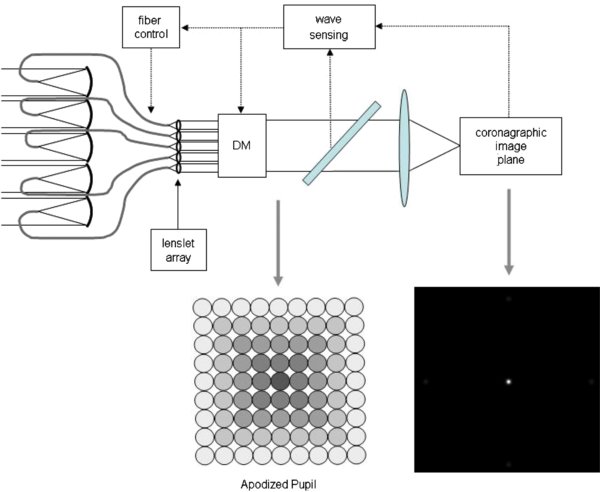
Figure 4. Schematic of a fiber-coupled MAT used as a phased-array coronagraph. Light from a small FOV around a star is collected by a close-packed array of small, inexpensive telescopes (the MAT), and then coupled into an SM fiber array. The envelope pupil, already apodized by the fiber array, is assembled at the fiber outputs by a lenslet array, and the wave front phase is corrected by a deformable mirror (DM) and fiber stretchers. A final common focusing optic completes the coronagraph. (The PSF shown on a linear scale in the lower right is the same as that shown in Figure 5(b) on a logarithmic scale.)
Download figure:
Standard image High-resolution imageIn the ideal case, the light in the demagnified pupil takes the form of a segmented wave front with phase steps set by the companion's off-axis angle (Figure 3), but in practice random phase errors between the segments will also be present. In fact, the pupil-plane phase accuracy needed in the MAT case is identical to that of any other coronagraphic system, but the wave front accuracy requirement now translates to the accuracy of matching phases and dispersions between the individual pupil elements. In the case of an all-reflective delay-line based relay, phase matching is straightforward. On the other hand, in the case of a fiber-relay, the fiber transmission properties must also be matched to high precision, requiring either a very well matched or a well corrected SM fiber array. In practice, the only way to achieve the necessary matching is no doubt to provide active control over the relevant properties: a DM to provide monochromatic OPD control for either type of relay, and a fiber "stretching" capability to provide dispersion control in the fiber-based case (e.g., Simohamed et al. 1999). For a wave front error σ across a passband Δλ due to a fiber length mismatch of ΔL, the temporal dispersion between fibers must be less than σ/(vΔLΔλ), where v is the propagation velocity. Setting v ∼ c, the speed of light, the dispersion (in ps km−1 nm−1) must then be less than 3σnm/(ΔLμmΔλμm), where the units of each quantity are given as subscripts. For a match of e.g., 0.1 nm across a 100 nm wide band, the dispersion mismatch must then be less than 3/ΔLμm ps km−1 nm−1, which is compatible with a few existing low-dispersion fibers, assuming also a modest degree of active fiber matching. Progress is being made in fiber dispersion control (Kotani et al. 2004), and low-dispersion fiber options are also increasing due to the advent of novel types of photonic fibers. The availability of appropriate fibers should thus not be considered a show stopper by any means, especially in the long term.
3. RELATIONSHIP TO PREVIOUS CONCEPTS
Several of the constituent ideas discussed to this point have been considered previously in other contexts, but to my knowledge, never as the direct high-contrast imaging system described here. Arrays of subapertures within a larger telescope aperture have been considered in the context of, e.g., pupil plane interferometry, nonredundant masking and pupil remapping (Perrin et al. 2006; Lacour et al. 2007; Ireland et al. 2008), but such an approach has in general not been considered for direct image generation. This is likely because of the need to phase multiple subapertures, but such capabilities will in any case soon improve due to the advent of extreme AO systems. Another perceived limitation may be the small FOV provided by SM fibers, but as discussed, this is not an essential limitation for the small-FOV case. Moreover, subarraying concepts typically assume an array of subapertures within an existing large monolithic telescope aperture, and so do not propose doing away with the monolithic telescope in favor of a close-packed array of small telescopes. Basically, unlike the MAT imager proposed here, the interferometric concepts (e.g., Perrin et al. 2006) are directed at interferometric fringe measurements, rather than at generating a direct optical image. The two methods of employing a fiber array are thus quite complementary: one operates in the pupil plane, and the other in the focal plane.
Other concepts such as the "hypertelescope" (Labeyrie 1996) and the sparse aperture imaging case also consider the use of multiple apertures, but these are typically assumed to be individually large, few in number, and widely separated. Such an approach thus resembles long-baseline interferometry more than imaging, and usually requires pupil plane reconfigurations to achieve a high enough degree of spatial frequency coverage to provide a good image (even without considering the very high contrast case).
The use of SM fibers for spatial filtering has also been considered earlier, primarily in the context of nulling interferometry, where they are used to improve null depths (Ollivier & Mariotti 1997; Serabyn et al. 1999). Moreover, one concept for a backend nulling interferometric coronagraph relies on a passively matched fiber array (Mennesson et al 2003), in contrast to our proposal of an actively controlled fiber array. That concept also assumes one or more large and highly accurate telescopes as the collecting elements, as opposed to a large number of small, inexpensive telescopes.
Thus, to clearly define the optical configuration under discussion here, in the MAT approach the large, accurate telescope is eliminated entirely in favor of a array of small (∼10 cm), inexpensive telescopes densely filling a large (several metres) envelope pupil, thus mimicking a filled aperture telescope. The aim is to provide a final optical image, rather than interferometric fringe measurements, although these could be provided in an alternate operational mode if desired. We now turn to the final essential question—what are the advantages of a MAT for high-contrast imaging?
4. THE PHASED-ARRAY CORONAGRAPH (PAC)
Thus far an alternative method of collecting and phasing light across a large envelope pupil has been described, but its applicability to the high-contrast imaging case remains to be explored. In this regard, the decoupling of the neighboring pupil elements from each other in a MAT suggests making use of this independence to provide a capability to adjust or "tune" the field in each pupil element to a desired value. Such a capability would in effect provide a means of apodizing the pupil plane field, with immediate applicability to high-contrast imaging. Note that such an apodization capability would be intrinsic to the MAT relay, with no additional apodizing masks needed.
Can such an apodizer be realized at optical wavelengths? Both fiber-based and delay-line based relays can easily be envisioned as providing adjustable phases (the control of relative phases by means of delay lines is obvious, while the combination of a DM and an array of fiber stretchers as described earlier would be needed for a fiber-based relay). On the other hand, since the power transmitted by a fiber can be adjusted simply by tuning the amount of light coupled into the fiber, a fiber-based relay provides a very straightforward means of amplitude apodization. To tune the coupling of the incident light into the input ends of the individual fibers, all that is needed is control of the pointing of the incident light onto the fiber tips, and such pointing control would be needed anyway for coupling optimization. On the other hand, in the delay-line based case, each beamlet would need a variable attenuator of some sort (such as a mask of variable area). Thus with appropriate control elements, arbitrary (albeit "digitized") intensity and phase apodizations of a MAT-based pupil are possible.
With both the amplitude and phase of each pupil element adjustable, the envelope pupil apodization can be set arbitrarily, thus enabling tunable, complex pupil apodization. A tunable complex apodizer stands in marked contrast to most other apodization schemes proposed to date, which tend to rely on fixed, real pupil-plane apodization. In fact, the tunable MAT apodization described resembles a radio-wavelength phased array, in which the field in each element of a filled array is set so as to provide the desired beam shape. This suggests the nomenclature "phased-array coronagraph" (PAC) to describe a MAT array with adjustable elements. Note that with a PAC, since the pupil apodization is provided by the relay optics used to assemble the pupil, the only remaining step needed to provide a high-contrast coronagraphic image after pupil assembly is the transformation of the pupil to the image plane with a common focusing optic (Figure 4). The main remaining issue is then the quality of the resultant image.
As usual, the focal-plane field distribution is the Fourier transform of the pupil plane field. With a regular array, periodic sidelobes will appear (as with a grating) at off-axis angles, θ, spaced by λ/s, where s is the grid or "grating" spacing of the MAT (s = d + g, where g is the gap between collectors). For small gaps (s ∼ d), the first "grating" sidelobe, at λ/s, lies well beyond the edge of the dark hole at λ/2d. Indeed, it is only when the gap size is as large as the size of the collectors that the first sidelobes can enter into the dark-hole region. As such, for g << d the potential central dark-hole region (inside λ/2d) is little affected by sidelobes at λ/s (e.g., Figures 5 and 6).

Figure 5. (a) Aperture distribution, (b) PSF (on a log scale), and (c) PSF intensity crosscut along a diagonal, for a MAT with a delay-line based relay with uniform illumination within each circular subaperture and g/s = 1/8 (i.e., gaps 1/8 of the aperture spacing). The pupil segmentation introduces "grating" sidelobes spaced by λ/s. The dark hole corrected by the DM can occupy a central square of side λ/d, so it extends roughly halfway to the neighboring sidelobes. Inside the potential dark hole (inside a diagonal distance of 23 λ/D in this case), the monolithic-telescope PSF (light curve) and the PAC PSF (dark curve) agree quite closely, and both are less than 10−10 inside the dark hole beyond 4λ/D.
Download figure:
Standard image High-resolution image
Figure 6. (a) Aperture distribution, (b) PSF (on a log scale), and (c) PSF intensity crosscut along a diagonal, for a MAT with a fiber-array based relay with Gaussian illumination within each square subaperture (the illumination here is assumed to fall to e−1 at the center points of the square lenslet edges). As in Figure 5, the pupil segmentation introduces "grating" sidelobes spaced by λ/s. The dark hole corrected by the DM can occupy a central square of side λ/d, so it extends roughly halfway to the neighboring sidelobes. Inside the potential dark hole (inside a diagonal distance of 23 λ/D in this case), the monolithic-telescope PSF (light curve) and the PAC PSF (dark curve) agree quite closely, and both are less than 10−10 inside the dark hole beyond 4λ/D.
Download figure:
Standard image High-resolution image
As in the monolithic telescope case, the suppression of the stellar point-spread function (PSF) within the dark-hole region follows from the envelope pupil apodization. As a proof of concept, we briefly consider here the case of amplitude apodization. PSFs for various cases were computed numerically for both types of relay, with rather similar results. As an example, Figures 5 and 6 compare the PSFs for the cases of delay-line based and fiber-based relays, respectively, with an equivalent single-aperture PSF. The MAT's envelope pupil was apodized by a "digitized" version of a continuous Gaussian function, with the value within each subaperture fixed at the continuous Gaussian's value at the center of that subaperture. The intensity across each individual pupil element was then further defined by the relay type assumed: for the delay-line case, the subpupil illuminations are uniform, while for the case of a fiber-based relay, the subpupil illuminations are given by a truncated Gaussian distribution (reaching e−1 at the subpupil radius here), in order to mimic the effect of illuminating an individual lenslet in a lenslet array by a SM fiber output beam. As Figures 5 and 6 show, the desired 10−10 contrast levels can indeed be reached with a MAT within about 4λ/D of the optical axis for either type of relay, and so a PAC can in principle provide a stellar PSF suppression comparable to that predicted for other types of coronagraph (e.g., Guyon et al. 2006).
While a PAC is thus capable in principle of providing the desired contrast, it can also provide a much higher degree of flexibility than a fixed-mask intensity apodizer, because any intensity or phase apodization can be obtained simply by tuning the fiber intensities and phases. Phase apodization (e.g., Codona et al. 2006) brings the benefit of high throughput, but amplitude apodization is of course more familiar. The combination of the two apodizations remains largely terra incognita in the optical domain. Moreover, several of the outer fibers could also simply be "turned off" (by mispointing their inputs), providing the ability to generate arbitrary envelope pupil shapes such as squares, rectangles, circles, etc. (excepting those with very fine structures) at will. Indeed, the MAT array itself need not fill any specific envelope pupil, which may be round, square (e.g., Nisenson & Papaliolois 2001), rectangular (for a smaller IWA along one axis, as well as compactness for launch), hexagonal (for close packing), etc. Thus, a PAC provides a very high degree of flexibility indeed: in both the amplitude and phase distributions, as well as in the pupil geometry. Moreover, in principle the pupil can also be remapped by laterally translating the outputs of the fibers, yielding anything from densified pupils (allowing somewhat wider input-plane subpupil spacings) to sparser output pupil distributions, such as, e.g., a "digitized" version of the phase-induced amplitude apodization coronagraph of Guyon (2003). Moreover, interweaving the fibers leads to even further potential variants, akin to, e.g., sheared-aperture nullers (Mennesson et al. 2003). However, the exploration of these numerous options open to a MAT is left to follow-on work.
Of course many practical limitations to a PAC–MAT's performance may apply, as they do for any other type of coronagraph. One of these is efficiency losses, of which there are two types specific to MATs. First, for either type of relay, some light is lost to the off-axis sidelobes, and second, in the fiber-based relay, fiber-related coupling losses arise. The light lost to the sidelobes can be estimated in straightforward fashion from the array theorem (e.g., Hecht 1987) which states that the net focal plane field of an array of identical apertures is given by the product of the single-aperture field distribution with the sum of the fields arriving from the centers of each of the subapertures. The latter term accounts for the sidelobe pattern, while the former determines the relative magnitudes of the sidelobes. For uniform subapertures (the delay-line case), the single-aperture focal plane pattern is the Airy pattern, which is a function of the argument πθd/λ (Born & Wolf 1984). At the first off-axis sidelobe, θ = λ/s, the argument of the Airy function is then πd/s. Since the lowest sidelobe level in general calls for the largest subaperture, the best possible case occurs for d = s, for which the value of the Airy function (evaluated at π) is 0.033. More conservatively, as in the calculations of Figure 5, one can assume d/s = 7/8, for which the value of the Airy function is 0.096. The first diagonal sidelobes are given roughly by the squares of the on-axis sidelobes, and so are generally much smaller (e.g., in the range 0.001–0.01 for the examples discussed above). Most of the scattered light is thus contained in the four sidelobes nearest the center, implying a central-lobe efficiency of ≈ 0.6–0.87 for the cases considered. (Note that Figures 5(b) and 6(b) are on a log scale, while Figure 4 shows a PSF on a linear scale).
The additional coupling losses related to the use of fibers are also straightforward. The coupling of the incident light into the near-Gaussian fiber mode yields a coupling efficiency of ≈ 0.8 (Shaklan & Roddier 1988), while the truncation of a fiber's SM output beam at a subsequent lenslet yields efficiencies of, e.g., 0.63 (for e−1 illumination of round lenslets) to 0.71 (for e−1 illumination of square lenslets, as in Figure 6). Somewhat higher efficiencies are possible with steeper lenslet illumination tapers, but at the cost of higher sidelobe losses. Thus, to first-order, fiber-related losses are ∼1/2. Finally, in order to determine the ultimate performance limits of the approach, scattered light levels, as well as bandwidth and polarization limitations will need to be evaluated in detail.
5. SUMMARY
Combining two ideas leads to the concept of a phased-array coronagraph. First, the use of a MAT array consisting of small, closely spaced, inexpensive collectors provides a system optimized specifically for the small FOV case, in which the targeted field of view, the DM's domain of influence (the dark hole), and the fiber's SM FOV (in the case of a fiber-based relay) are all approximately matched. Note that such a system is well matched not only to the faint exoplanet case, but potentially also to other small-FOV cases, e.g., circumstellar disks and galactic nuclei. Second, the concept of a phased-array coronagraph, in which the complex field in each element of the pupil can be individually tuned, has been shown capable, in principle, of providing the contrast levels needed for terrestrial exoplanet imaging. Moreover, the flexibility inherent in a PAC allows the implementation of a large range of coronagraphic apodization options (pupil amplitude, phase, and shape are all tunable) in a single system. A further important advantage of the PAC–MAT is its easy scalability: simply adding more collectors yields larger envelope apertures. Since the cost of an array of small collectors should be moderate compared to a large, highly accurate telescope, a PAC–MAT thus allows consideration of larger envelope pupils than would be possible with a standard telescope. While larger apertures are desirable at any wavelength, note that they may be particularly beneficial at the longer wavelengths (1–1.5 μm), where larger apertures are essential, and where fibers are very well developed. On the other hand, system integration costs (due to wave front sensing and phase control) should not be much different from those inherent in any other coronagraphic approach, since the measurement requirements are similar. Thus, while the PAC is a radical departure from the standard large-telescope approach to coronagraphy, it nevertheless seems promising in several regards. However, with such a novel concept, laboratory demonstrations of the needed degree of control and performance will of course be vital. Finally, note that while this discussion has focused mostly on a lower cost space mission, the approach may find applicability to large ground-based telescopes as well.
The research described herein was carried out at the Jet Propulsion Laboratory (JPL), California Institute of Technology, under a contract with the National Aeronautics and Space Administration. I thank S. R. Martin, K. Liewer, A. Ksendzov, and other colleagues at JPL for stimulating discussions of this idea, and the referee for numerous comments that led to a much improved paper.