
Abstract
Composite materials exhibit advantages from the combination of multiple properties, which cannot be achieved by a monolithic material. At present, the use of composite materials in miniaturized scale is receiving much attention in the fields of medicine, electronics, aerospace, and microtooling. A common method for producing miniaturized composite parts is micromanufacturing. There has been, however, no comprehensive literature published that reviews, compares, and discusses the ongoing micromanufacturing methods for producing miniaturized composite components. This study identifies the major micromanufacturing methods used with composite materials, categorizes their subclasses, and highlights the latest developments, new trends, and effects of key factors on the productivity, quality, and cost of manufacturing composite materials. A comparative study is presented that shows the potential and versatility associated with producing composite materials along with possible future applications. This review will be helpful in promoting micromanufacturing technology for fabricating miniaturized products made of composite materials to meet the growing industrial demand.
Export citation and abstract BibTeX RIS

Original content from this work may be used under the terms of the Creative Commons Attribution 3.0 licence. Any further distribution of this work must maintain attribution to the author(s) and the title of the work, journal citation and DOI.
1. Introduction
Recently, the use of miniaturized products has been strongly increasing throughout the globe [1]. There has been a continuously growing demand for compact, multifunctional, integrated miniature products. The demand is significant in the fields of electronics [2], microtooling [1], aerospace [3–5], medicine and biomedicine [5–7], information technology and telecommunications [8], automobiles, and microrobots [9, 10]. Consequently, products and devices are getting smaller, down to microscale, due to a near-future demand for nanoscale. This trend to miniaturization has, in fact, moved very quickly during the last two decades, driven primarily by electronics and silicon (Si)-based products. Therefore, Si-based micromanufacturing technologies, e.g. microelectromechanical systems (MEMS), photolithography, the lithographie, galvanoformung, abformung (LIGA) process, and electrochemical deposition [11, 12], have reached a mature level. Nevertheless, Si-based products have some intrinsic limitations with respect to geometry (limited to two dimensions (2D) and 2.5D), material (only Si), mechanical performance (limited motion, strength, and durability), and cost (not amenable to mass production) [11–13].
These issues have led researchers to find alternatives for producing three-dimensional (3D) microparts with the desired strength, better durability, complex geometry, better surface finish and cost-effectiveness, using metallic and ceramic alloys and their composites [2, 13]. There has also been noticeable progress in micromanufacturing of different metal-, ceramic-, polymer-, and composite-based components. Their fabrication methods, operating principles, size effects due to miniaturization, batch production, and energy and material savings have been thoroughly researched [13–15]. Numerous books and articles are also available that point out various critical factors and features pertinent to micromanufacturing of these materials.
However, the possibilities of using bulk materials, such as metals, ceramics, polymers, and their alloys, are so saturated that it may be difficult to achieve the highest material properties, such as durability and reliability of the components, even when using the most advanced techniques [16]. Composite materials, on the other hand, exhibit endless possibilities for meeting many of the emerging industrial requirements, in terms of extreme mechanical, electrical, magnetic, optical, and thermal properties, that cannot be met by monolithic materials. The main advantages of composite materials are their high strength, toughness, stiffness, and resistance to creep resulting in less corrosion, wear, and fatigue compared to conventional materials [16, 17]. By choosing an appropriate combination, it is also possible to attain specific properties, such as a composite of copper–aluminum (Cu–Al) clad, which are lighter, stronger, more solderable, and more electrically conductive compared to individual alloys [18, 19]. Therefore, composite materials are indispensable in a variety of applications today from micro- to nanoscale.
Although micromanufacturing techniques for monolithic materials are plentiful, not all of them are equally applicable to the production of microcomponents of composite materials [20]. In addition, substantial research has been conducted on micromanufacturing of composite materials. However, this research is focused on an individual technique. Therefore, an article reviewing the existing micromanufacturing techniques of composite materials, highlighting the latest developments and future trends, will significantly benefit the scientific community and advance the micromanufacturing of composite materials. In the work presented here, state-of-the-art micromanufacturing techniques for producing microcomposite components incorporating superior properties are reviewed.
A fundamental description defining the concept of micromanufacturing and composite materials is provided first followed by an all-embracing but simple categorization. Since the field of composite materials is vast, the focus is primarily on metal- and ceramic-based composite materials, excluding organic and polymeric composites. Therefore, cutting-edge micromanufacturing methods of metal matrix composites (MMCs) and ceramic matrix composites (CMCs) are extensively reviewed, highlighting the latest developments and future trends/research scope. The key factors influencing productivity, cost, and quality of the micromanufacturing of composite materials, such as size effects and matrix-reinforcement interfacial characteristics, are also addressed and discussed. To demonstrate the potential for micromanufacturing of composite materials, a bimetallic composite of ceramic and steel was fabricated by a novel micromanufacturing method, namely hot compaction diffusion bonding (HCDB). The results obtained are presented and discussed. Finally, the progress on analytical modeling and simulation of the micromanufacturing of composite materials is presented. A comparative study is also presented that shows the potential for and versatility of producing composite materials along with possible future applications. This review will be helpful for promoting micromanufacturing technology for fabricating miniaturized composite components with attractive properties to meet the growing industrial demand.
2. Fundamentals of micromanufacturing and composite materials
2.1. Micromanufacturing
The concept and/or definition of micromanufacturing has been addressed by a number of researchers and industrial personnel, as reported in earlier studies [2, 11–15]. The simplest definition of micromanufacturing is a system for producing small-dimensional parts occupying less space and consuming less resources and energy by downsizing the complete production process. Since the equipment size is reduced, the mass of the system can be reduced dramatically. This results in reduced energy consumption, overhead cost, materials requirement, noise, and pollution and eventually facilitates a more environmentally friendly and viable production process. Due to a reduced manufacturing cycle and higher tool speed, micromanufacturing also leads to higher production rates. A study conducted in [21] demonstrated the influence of miniaturization and pointed out that a 1/10-scale reduction of the production facility may result in a 1/100-scale reduction of energy consumption when compared to that of a conventional production system/factory. The most noteworthy improvement of micromanufacturing is its ability to produce components having a feature size of less than 100 μm [22, 23], close to the size of a human hair. Figure 1 shows micromachined parts made of aluminum oxide (Al2O3)-reinforced 316 L stainless steel composite materials that combine the hardness of ceramic and the strength of steel. A novel method, called the 'soft molding technique,' was used. The authors [20] claim that the hardness of 316 L stainless steel was improved by 1.8 times, enabling the parts to be stronger, harder, and more wear resistant.

Figure 1. Microcomposite parts made of Al2O3-reinforced 316 L stainless steel, combining the hardness of ceramic and the strength of steel: (a) microgear and (b) piston and linking rod. Reprinted from [20], Copyright (2009), with permission from Elsevier.
Download figure:
Standard image High-resolution imageThere are a number of techniques and processes that are used to manufacture miniaturized components. Based on the materials used, micromanufacturing can be broadly classified into two major categories: silicon and nonsilicon. In nonsilicon-based micromanufacturing, the materials usually dealt with are metal, ceramic, polymeric, and composite. Consequently, a number of different manufacturing techniques are involved and are being practiced in the industry. A useful, simple, and all-embracing classification is presented in table 1, including typical applications and common materials used. There is also a common trend of combining multiple processes together, termed hybrid micromanufacturing [24]. The type of energy involved in these processes includes mechanical, electrical, chemical, electrochemical, laser, and electron beam [25]. The working principles entailed include mechanical forces, thermal effects (melting/vaporization), dissolution, ablation, recomposition, plastic deformation, consolidation, lamination, and sintering [24, 26]. Similar to macroproducts, microcomponents, based on the way they are produced, can also be classified as subtractive, additive, joining, forming, and hybrid processes [3–5, 27–30].
Table 1. Micromanufacturing techniques [2–5, 13–33].
| Major type | Subtypes | Geometry | Common materials | Typical parts | Typical application |
|---|---|---|---|---|---|
| Microforming—conventional | Microrolling (cross-wedge, ultrathin, flexible) | A few to 10 s of microns | Metals (Al, Cu, Ni, steel, Mg, Ti), alloys, and composites | Microcans, pins, tubular parts | Sheet metal, medical devices, implants |
| Microforging | Hundreds of microns | Metals, metallic alloys, polymers | Microscrews, cans, gears, etc | Microdevices, housing, and assembly | |
| Microextrusion (forward, back-ward, cross) | A few 100 nm to 10 s of microns | Metals, metallic alloys, polymers, composites | Microgears, pins, screws, gear shafts, cans, etc. | MEMS devices, watches, mechanical and electrical parts | |
| Microdeep drawing | Dia < 1 mm, 100 μ thickness | Various metals and composites | Microcups, housings, etc. | Electron guns, pressure sensors, UV sensors, etc. | |
| Microstamping (punching, blanking, bending) | Tens to several 100 μm | Metals, metallic alloys, (e.g. Al, Cu, Ni, steel), polymers | Lead frames, casing, microcups, gears, etc. | MEMS devices, electronics, medical, optical, and chemical | |
| Microembossing, coining | A few 100 nm to 10 s of microns | Polymers, glass, Al, Cu, brass, steel, etc. | Functionalized (2.5D) structures | Microoptical, fluidic devices, dies/molds, etc. | |
| Microforming—advanced | Microhydroforming | Dia < 1 mm, 100 μ thickness | Various metals and composites | Microcups, tubes, complex shaped parts | Sheet metal, high-precision microparts |
| Laser-assisted microforming | Several 100 s of microns | Various metals | Lead frames, 2-3D microparts | Microoptical, fluidic devices, dies, molds, etc. | |
| Microeletroforming | Dia < 1 mm, 100 μ thickness | Various metals | High aspect ratio microparts, | Microoptical, fluidic devices | |
| Micromachining—conventional | Microdrilling | A few μm dia, 100 μm long | Metals, ceramics, polymers, composites | PCB board, microparts with holes, etc | PCB industry, medical, electronic, aerospace, optical |
| Micromilling [28] | Several 100 s of microns | Metals, polymers, alloys, composites | Complex 3D parts, pins, microgears, shafts | Microoptical, fluidic devices, dies, molds, etc. | |
| Microturning | A few 100 nm to 10 s of μs | Metals, metallic alloys, polymers, etc. | Complex 3D parts, microshafts, etc. | Microdevices, dies, molds, etc. | |
| Microgrinding | Several 100 s of microns | Metals, ceramics, polymers, composites | Microdrill, gears, shafts, hard-to-machine parts | Microtool industry, medical, electronics, aerospace | |
| Micromachining—advanced | EDM [27] | A few to 100 s of microns | Functional materials, conductive ceramics | Microgear, dies, mold fluidic devices, implants | Medical, electronics, micro tool industry, etc |
| Laser micromachining | 100 s nm to 10 s of microns | Polymers, glass, Al, Cu, brass, steel | Functionalized (2.5D) structures | Microoptical, fluidic devices, dies/molds, etc | |
| Jet machining (abrasive, water) | Several 100 s of microns | Glass, PMMA, PDMS, ABS, PTFE, polymers [33] | Complex 2-3D parts, microgears, shafts, | Microfluidic devices, MEMS, medical, electronic | |
| Ultrasonic | Submillimeter | Ceramic and brittle materials [32] | Complex, difficult-to-machine microparts | Microfluidic devices, MEMS, electronics | |
| Electron beam | Nanomachining | Various metals | Ultraprecision microparts | Microtool industry, medical | |
| Electrochemical | Submillimeter | Chemically reactive materials | Micromolds, dies, punches | Microdevices, microtooling, housings | |
| Microcasting | A few 100 μm to submillimeter | Tool steel, metal, ceramic powders | Micromolds, dies, punches, shafts, gears | Micromechanical, electronics, biotechnology | |
| Microinjection molding | Microns to submillimeter | Polymers, PDMS, ABS, PTFE | Various shaped 2D-3D microparts | Microoptics, microfluidics |
2.2. Composite materials
With the rapid development of the modern manufacturing industry, composite materials are being extensively used as advanced multifunctional materials in various fields, such as electronics, aeronautics, medicine, automobiles, and machining tools, due to their unique properties that eliminate traditional limitations due to the physical and mechanical performance of monolithic materials [34, 35]. For example, tungsten carbide (WC) has good hardness and wear resistance but poor strength and toughness [36, 37], while high strength steel has excellent strength and toughness but low hardness and wear resistance [38–40]. A layered composite of WC and high strength steel can combine their advantages and be used in many engineering applications.
A composite material can be defined as a material fabricated from two or more integral materials with considerably different physical and chemical properties that, when combined, produce a material with characteristics different from the individual constituents. The individual constituents stay separate and distinct within the completed structure, differentiating composites from mixtures and solid solutions [41, 42]. Thus, every composite material, by definition, has essentially two components, a matrix, i.e. a continuous phase, which is armored by a reinforcement, i.e. a discontinuous phase. In cases where there are three or more constituents, the composite is termed to be a hybrid composite [43, 44]. Composites are available all around us in nature, e.g. wood, bone, tissue, etc. In industry, most of the composites are based on metals, ceramics, and polymers [17]. Composites can be classified in various ways. A useful and all-embracing classification can be made based on matrix and reinforcement, as shown in table 2. The MMCs containing reinforcement, e.g. ceramic particles, whiskers, and fibers, are gaining much importance these days. The CMCs are considered to be the newest entrants in the field [45]. In this study, particular focus is given to micromanufacturing of metallic- and ceramic-based composite components.
Table 2. Fundamental classification of composite materials [34–44].
| Constituent | Materials | Class | Example |
|---|---|---|---|
| Matrix constituent | Organic composites | Polymer (PMC) | Wood, bone, speed boat, tennis racket |
| Carbon–carbon | Refractory, hot pressed die, heating element | ||
| Metal matrix composites | Piston, crankcase, cylinder, brake | ||
| Ceramic matrix composites | Cutting tool, turbine blade, combustor, wear parts | ||
| Reinforcement applied | Fiber reinforced | Continuous fiber | Woven, stiched mat |
| Discontinuous fiber | Chopped strand mat, oriented strand board | ||
| Laminar composites | Plywood, furniture, Al–Cu sandwich, WC-steel bimetal | ||
| Particulate composites | Particulate in flake form | Body panels, bumpers, dashboards, and intake manifolds | |
| Particulate in powder form | Cell phone casings, electrical products, computer housings |
2.3. Metal matrix composites
The need for new materials is constantly important to manufacturing industries. Better mechanical properties, reduced weight, and lower cost are the key factors for developing new materials [46]. Since current bulk materials eventually reach their limits, engineers are looking to composites to obtain extra strength, stiffness, and durability [47]. Metals and their alloys are largely manufactured and shaped in bulk form; however, they can also be intimately combined with another material in order to improve their performance. The resulting materials are MMCs [48]. Significant advancement in the development of MMCs has been achieved over the past few decades, with their incorporation into important industrial applications. These pioneering materials have opened up infinite possibilities for present material science and development [49]. The characteristics of MMCs can be designed into the material, custom-made, and dependent on the application [49]. When compared to polymer matrix composites, MMCs offer improved material properties. For example, compared to resin, metal matrices provide higher tensile and shear molduli, higher melting temperature, a lower thermal coefficient of expansion, better dimensional stability, better joinability, high ductility and toughness, and the ability to be fully dense [50, 51]. MMCs essentially consist of a metal or alloy as matrix material and a reinforcement of different kinds and shapes. Table 3 presents a detailed classification of MMCs with typical examples of materials used, their applications, and fabrication techniques.
Table 3. Matrix and fiber materials used in MMCs and their fabrication techniques.
| Main types | Typical example | Typical application | References | |
|---|---|---|---|---|
| Common matrices used in MMCs | Al, Mg, Cu, Ti, Ti aluminides, Ni, Ni aluminides, Ni superalloys, Fe alloys, and intermetallic compounds | [47, 51] | ||
| Reinforcement used in MMCs | Particulate reinforced | Al-ceramic, AlSi-SiC | Cast brake disk, brake rotor disc | [52] |
| Short fiber or whisker | Al-5% Al2O3 | Diesel pistons | [53] | |
| Continuous fiber | Ti alloy-40% SiC | Aero-engine component | [54] | |
| Laminate composites | SS304-SS420, Al–Cu | Layered steel sheet | [55] | |
| Liquid state processes | Casting or liquid infiltration | Al-SiC, Al-Al2O3, Mg-SiC, Mg-Al2O3, | Bracing, piston rods, frames, piston and pins | [49] |
| Squeeze casting or pressure infiltration | AI203-Zr02 fibers with a Ti-AI matrix | Structural component | [56] | |
| Centrifugal casting | Bronze-WC fiber | Brake rotors | [51] | |
| Stir casting | 6061Al-10%SiC | Duralcan® components | [57] | |
| Solid state processes | Diffusion bonding | B-Al, Gr-Al, Gr-Mg, and Gr-Cu | Spacecraft tubes, plates, and panels | [58] |
| Deformation processing | ||||
| Extrusion | Cu-Nb, Cu-YBaCO | Superconductor | [49] | |
| Drawing | Al-glass fiber | Laminate cup | [59] | |
| Rolling | Al–Cu | Laminate sheet | [60] | |
| Deposition (spraying, CVD, PVD, plating) | Zn, steel, Mo, substrate materials | Corrosion resistant components | [61] | |
| Powder metallurgy techniques | Discontinuously reinforced | WC-Co, Cu-W, Pb-C, brass-Teflon™ | Cutting tools, welding electrodes, bearings | [62] |
2.4. Ceramic matrix composites
Metal and metallic composites have been extensively used in industry; however, in certain applications, particularly involving high temperatures, they have reached a limit in their potential for further development. Ceramics, on the other hand, offer the advantage of operating at substantially high service temperatures. In addition, low density, high hardness, and chemical inertness extend potential ceramic performance limits beyond those achievable by metallic materials. Nevertheless, ceramic materials have intrinsic limitations of brittleness and poor strength reliability. In an effort to overcome these drawbacks, significant progress has been reported in the last two decades. The most important development appeared in the form of composites, i.e. the combination of multiple constituent phases with suitable microstructures in order to obtain the desired properties. Generally, ceramic composites are composed of two or more distinct ceramic phases combined on a microstructural scale to provide the properties that cannot be achieved by monolithic materials [63, 64].
In the arena of composite materials, CMCs are considered to be the latest entrants with a set of impressive properties and potential applications [45]. Due to advancements in the manufacturing process and technology, a wide variety of types of CMCs have come into use to meet the continuously growing industrial demand. These can be categorized into four major groups: (1) reinforced CMCs, (2) graded and layered composites, (3) refractory composites, and (4) nanostructured composites. Similarly, there are a number of different techniques for manufacturing CMCs, which are classified based on the materials used, kind of composites, typical applications, and fabrication principle. Table 4 summarizes different matrices and fiber materials used in CMCs and different fabrication techniques with examples.
Table 4. Matrix and fiber materials used in CMCs and their fabrication techniques [63–69].
| Types | Subtypes | Examples | |
|---|---|---|---|
| Matrix materials | Ceramics | Single oxides | Al2O3, ZrO2, TiO2, MgO, SiO2, SiO4 |
| Mixed oxides | Mullite (3AI2O3·3SiO2), Spinel (MgO· Al2O3) | ||
| Carbides | SiC, B4C, TiC | ||
| Nitrides | BN, Si3N4 | ||
| Intermetallics | NiAI, Ni3AI, TiAI, Ti3AI, MoSi2 | ||
| Elemental | Carbon (C), boron (B) | ||
| Glass-ceramics | Li2O- Al2O3-SiO2 (LAS), MgO- Al2O3-SiO2, SiO2-Al2O3-MgO-K2O-F | ||
| Glass | Soda-lime, borosilicate, silica, fused quartz | ||
| Reinfor-cement materials | Particulate | SiC, TiC, Al2O3 | |
| Discontinuous fiber | Whiskers | SiC, TiB2, Al2O3 | |
| Short fibers | Glass, Al2O3, SiC,(AI2O3 + SiO2), vapor-grown carbon fibers | ||
| Continuous fiber | Oxides | Al2O3, (AI2O3 + SiO2), ZrO2, silica-based glasses | |
| Nonoxides | B, C, SiC, Si3N4, BN | ||
| Fabrication techniques | Conventional techniques | Mixing matrix and fiber powders, cold press, and sintering | |
| Hot pressing of CMC powder mixture | |||
| Pressure-assisted hot pressing | |||
| Reaction bonding | |||
| Joining (layered composites): soldering, brazing, diffusion | |||
| Hybrid (combining two or more processes) | |||
| Advanced/novel techniques | Infiltration | Liquid infiltration | |
| Directed oxidation or the Lanxide™ process | |||
| Directed oxidation | |||
| In situ chemical reaction | Chemical vapor deposition (CVD) | ||
| Chemical vapor impregnation (CVI) | |||
| Others: sol–gel, pyrolysis, self-propagating high-temperature synthesis (SHS), spark plasma sintering (SPS), pulse plasma sintering (PPS), HCDB |
3. Microforming of composite materials
Microforming is one of the popular micromanufacturing methods, where the traditional metal-forming technology is scaled down to microscale. Microforming is usually defined as the forming of components or geometrical features with at least two dimensions in the submillimeter range. Microforming presents an emerging micromanufacturing technique due to a number of advantages over other micromanufacturing techniques. Process simplicity, better mechanical properties of the parts, high production rate, minimum material waste, and net shape characteristics are a few of the advantages [14, 70–73].
Figure 2 presents some microcomponents manufactured by microforming. A wide variety of material types are used for microforming, such as aluminum, copper, brass, nickel, titanium, magnesium, and steel. Recently, the use of composite materials has been receiving increased interest. Since material cost is a major concern in industrial production, replacing a part of the component with a cheaper material, while maintaining the desired functions of the part, may save significant cost. This, in fact, has generated increasing interest as a way to reduce the production cost. An example is shown in figure 2(b), where a brass part is replaced by cheaper steel. In addition, replacing part of the component with lightweight materials also results in reduced weight of the component. Thus, composite materials play a significant role in modern applications in terms of lower cost, lighter weight, and better mechanical properties. In this section, various cutting edge microforming technologies used to manufacture composite materials are presented as well as their future trends.

Figure 2. Miniature components produced by microforming: (a) microformed parts of various shapes [74] and (b) microdeep drawn parts of brass and steel [75]. (a) Reproduced with permission from [74]. (b) Reprinted from [75], Copyright (2013), with permission from Elsevier.
Download figure:
Standard image High-resolution image3.1. Microrolling of composite materials
Composite materials are popular because of their heavy industrial use, providing cheaper, lighter, and stronger alternatives to monolithic materials [76]. For example, the use of layered composite materials has recently received significant attention due to their lower cost and attractive mechanical, electrical, and magnetic properties. Laminated composite materials provide customizable properties for specific applications requiring high impact and fracture resistance [77, 78]. Such composite materials have a uniform distance between composite layers and are typically fabricated by physical vapor deposition (PVD) techniques, e.g. magnetron sputtering [79–81] and electron beam deposition [82–84]. Among mechanical means, rolling, hammering, and swaging are used to bond alternating sheets to fabricate a composite. However, rolling or roll bonding is reported to be one of the popular methods, due to good potential for commercialization due to its comparatively simple processing and low cost. Rolling can also be accompanied by a cold or hot system to customize the material functionalities. Usually, bottom-up PVD methods provide more refined and even microstructures while top-down mechanical techniques produce coarser, nonuniform microstructures. Nevertheless, uniformity of microstructures can be controlled to some extent during rolling by choosing materials with similar hardness and strain hardening rate, providing uniform layer deformation and reducing layer pinch-off.
Stover et al [85] fabricated a layered, microcomposite material of nickel (Ni) and Al using a repeated cold rolling method with initial billet thicknesses of 25 and 18 μm, respectively. They investigated the effects of thickness reduction and observed that at higher thickness reduction, less uniform layer deformation and more pinch-off occurs, compared to more gradual and smaller reduction at lower thickness reduction (figure 3). Eizadjou et al [86] implemented accumulative roll bonding (ARB) to fabricate an Al/Cu layered composite at room temperature and demonstrated the generation of nanostructured layered composite with superior properties. An increase in the number of passes may result in equiaxed grains with enhanced hardness [86]. As reported in [87], the flow stress ratio of two materials should be similar and chemically stable to achieve good metallurgical bonding between layers. Adding heat during microrolling can improve further grain refinement [88]. Another emerging approach is to add nanoparticles to improve the properties of composite materials. Yousefian et al [89] used titanium dioxide (TiO2) nanoparticles and observed significant improvement in tensile strength of aluminum MMC during microrolling. Thus, there are numerous techniques that could be implemented to enhance the properties of composite materials. However, the choice of materials used for microrolling is still limited, leading to a considerable scope of future research to attempt different combinations of materials with a number of potential future applications. In addition, as the trend is to obtain finer grain structure by improving material properties, severe plastic deformation (SPD) could be used to fabricate composite materials. Though there has been remarkable progress in SPD of bulk materials, their use in composite materials is limited [90–92]. The application of SPD in microrolling of composite materials may significantly improve the material properties and, therefore, deserves further research.

Figure 3. Microrolling of multilayered composite materials: (a) schematic presentation of cold rolling process and (b) microstructural cross-section image of the rolled Ni:Al laminate composite material. [85] (2013) With permission of Springer.
Download figure:
Standard image High-resolution imageTable 5. Summary of different micromanufacturing techniques of composite materials.
| Techniques | Underlying mechanisms | Common materials | Comments |
|---|---|---|---|
| Microforming | Microrolling, microdeep drawing microextrusion, microbending, microcompression | Metals (Al, Cu, Mg, Ni, Ti, steel) and metallic alloys | Grain refinement, controlled heat treatment, lubrication and nanoreinforcement can improve formability |
| Micromachining | Drilling, milling, shaping, turning nontraditional machining | Metals, ceramics, alloys, MMC, CMC | Reinforcement size and bonding strength of fiber/matrix is crucial |
| Microcasting | Investment microcasting, permanent mold microcasting, composite microcasting | Metals, alloys, and ceramics | Composite casting is an emerging technique |
| Microinjection molding | Conventional hybrid | Metals and their alloys | Ability of mass production; however, many factors are still to be examined |
| Microjoining | Solid-state diffusion bonding, diffusion soldering and brazing microwelding, bonding using nanoparticles, and metal/ceramic bonding | Metals, metallic alloys, ceramics, MMCs, CMCs | Provide a permanent connection of similar or dissimilar materials directly or by employing an interlayer |
3.2. Microdeep drawing (MDD) of composite materials
MDD is a fundamental microforming process and regarded as one of the most applicable sheet metal forming processes. It is widely used in many industries to produce microcomponents, such as microcylinder cups, rectangular cups, conical cups, spherical cups, hollows, and box-like parts [76, 93]. However, most of these microcomponents are made from bulk materials. Limited attention is paid to MDD of composite materials, though composite materials exhibit a number of attractive properties, as stated earlier. Laminated composite materials, for instance, can be used in manufacturing parts with different inner and outer conditions, such as corrosion, wear resistance, and thermal and electrical conductivities [94–96].
MDD of composite materials appears to be more complex than conventional forming methods. There are several associated parameters which cause problems. A number of defects may occur in the drawn parts, which must be accurately addressed and properly controlled to reduce the number of no-go parts as well as production costs. The parameters taken into account during MDD of composite materials include blank holding force (BHF), applied punch force, material properties of the blanks, thickness of the blanks, stacking sequence of the blanks, velocity of the punch, lubrication, and temperature conditions. In addition, the type of reinforcement used and its shape and size are also important. These factors are responsible for affecting the final products and can regulate the wrinkling effect, tearing effect, and fracture defects.
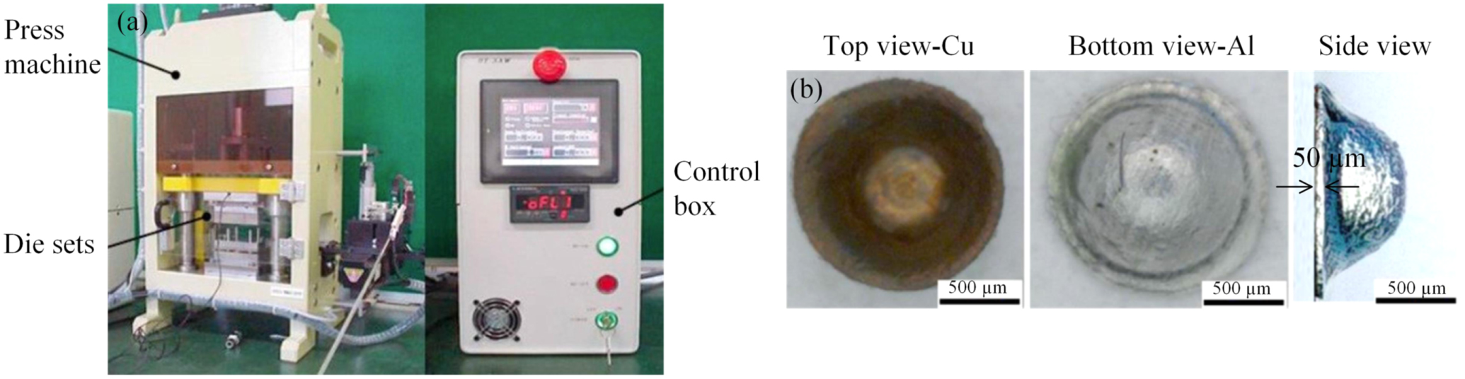
Many of these parameters are thoroughly discussed in conventional deep drawing as well as MDD of monolithic materials; however, they are not as developed in the case of composite materials. Jia et al [76] examined the effect of heating during MDD of 50 μm of an Al–Cu composite material (figure 4) and successfully fabricated a microcup without considerable fractures or wrinkles. Another important parameter is BHF, as reported in [94], which discusses MDD of an Al 1050 and stainless steel (SS) 304 laminate composite. Yin et al [18] examined the MDD of a cobalt (Co)-Al–Cu laminate composite and observed that an increase in holding time during heat treatment can improve the properties of the formed parts. Consequently, the interaction between the die and specimen plays a significant role in MDD of composite materials. The formability can also be greatly influenced by employing appropriate lubrication. Nanoparticle-based oil lubricant can improve drawability and reduce the forming load of composite materials, as observed in [93], which discusses MDD of an Al–Cu composite material. There has been some progress in MDD of composite materials; however, the literature still does not describe the interfacial behavior of different laminates and/or matrix-reinforcement interactions during the course of MDD. The material flow characteristics of different layers (prevention of defects, e.g. wrinkling and fractures) during MDD needs to be acutely analyzed. Investigation of the stress and strain distribution of the drawn composite parts also requires further research to develop this promising field.

Figure 4. Microdeep drawing and drawn parts: (a) desktop servo press machine DT-3AW and (b) observation of the microdeep drawn parts of an Al–Cu layered composite material.
Download figure:
Standard image High-resolution image3.3. Other techniques for microforming composite materials
In addition to the aforementioned microforming techniques, microextrusion, microstamping, microbending, microembossing, micropunching, microblanking, and microcoining are also attracting attention in the forming of microproducts that have a variety of applications. However, not all of these techniques have been implemented in the manufacturing of composite-based microproducts. Examination of the potential for using the above techniques to fabricate microparts from composite materials is clearly lacking [97–104]. However, there have been some innovative microforming methods reported in recent years for the fabrication of composite parts. Patel et al [105] reported a novel microblast-driven microforming method and fabrication of a bismuth oxide (Bi2O3)-reinforced Al composite micropart. A mathematical model and critical forming processes have also been proposed. Bending and contact strengths of a carbon-reinforced silicon nitride-silicon carbide (Si3N4-SiC) composite were examined by Dusza et al [106] and its fracture mechanisms were illustrated. Cui et al [107] fabricated a microlaminated titanium boride-titanium aluminum (TiB-TiAl) composite sheet by employing a multistep heat treatment and pressing process. Zhang et al [108] conducted a simulation of a tin oxide/silver (SnO2/Ag) particulate-reinforced MMC through microextrusion. The effects of the extrusion angle, the extrusion ratio, and the ram speed on the deformation and redistribution of particles during microextrusion were studied using the finite element (FE) method. When composite materials are microformed, the scenario may generally appear different than that of conventional techniques. The deformation behavior of reinforcement (particle distribution) used in the matrix plays a significant role in microforming. The size and type of reinforcement used and its interaction with the matrix material and tools may be a matter of substantial significance, which needs to be thorougly investigated.
4. Micromachining of composite materials
Even though composite materials are processed near net shape, further machining operations are generally inevitable to ensure the accurate function for the application. Since the cutting/machining mechanism for composite materials is not well understood yet, experimental study to reveal the nature of the cutting behavior of composite materials requires significant experimental tests. To improve the proficiency of experimental works and extract more information, experimental methods have been designed to study the machinability of composite materials. A Taguchi-method-based experiment was studied during the machining of Al [109, 110] and hybrid MMCs [111]. Another approach is response surface methodology, as reported in [112] for cutting forces and in [113] for surface roughness. In addition, FE methods are also used to investigate the cutting mechanism of composite materials, as reported in [114], to examine the cutting mechanism of SiC/Al MMCs. In this section, various factors that influence effective micromachining of composite materials are discussed. In addition, some advanced nontraditional techniques that are used for micromachining of composite materials are also illustrated.
4.1. Factors affecting the machining of composite materials
The microstructure and grain distribution of composite materials play a significant role in the machining of composite materials. The grain size of commonly used engineering materials subject to micromachining falls in the range of 100 nm–100 μm [115, 116]. The radius of the tool edge (i.e. roundness) and feed rate value are frequently considered to be in the range of several hundreds of nanometers to several micrometers, which is also comparable to crystalline grain sizes. Therefore, the influence of grain size, grain distribution, and overall crystallographic nature of the composite materials plays a crucial role in micromachining, as detailed in [115, 117, 118]. It has been reported that a homogeneous grain size distribution has a positive effect on better dimensional accuracy and high surface quality. The influences of metallurgical phases on cutting forces were studied by Vogler et al [119]. An FE model was proposed in [120–122] to evaluate the stress, strain, temperature, and damage distribution due to changes in grain size and grain distribution.
Another important parameter is the reinforcement used in a composite. Because of the presence of particulates/fibers, the material removal rate and chip formation mechanism appear differently in composite materials. Teng et al [114] carried out an FE simulation for the cutting mechanism of SiC/Al MMCs reinforced with micro- and nanosized particles using the FE method (ABAQUS). They reported that nanosized particles remained intact without fracture during the machining process and were more likely to produce continuous chips, in contrast to microsized particles that were easy to break and tended to form discontinuous chips (figure 5). Thus, a better machined surface quality with less defects can be obtained from nanosized, reinforced MMCs compared to their microsized counterparts. Based on the literature surveyed, the machining mechanism for composite materials is not yet fully understood, especially for micro- and nanoparticle-reinforced composites. Further investigation (theoretical and experimental) is required to reveal the fundamentals of micromachining of composite materials, in terms of stress and strain distribution, tool wear, failure mode, chip formation, and particle behavior.

Figure 5. Finite element analysis model setup for orthogonal aluminum-based MMCs reinforced with (a) nanosized SiC particles and (b) microsized particles. Reprinted from [114], Copyright (2018), with permission from Elsevier.
Download figure:
Standard image High-resolution imageAnother important factor is the effect of strengthening. Machining is principally a process where materials are continuously or discontinuously fractured and then driven away under comprehensive fracture criteria [123]. The improved mechanical properties of composite materials, such as yield strength and toughness, considerably influence the material's fracture characteristics. Several authors have attempted to estimate the reinforced yield strength by virtue of different strengthening mechanisms [124–126]. There are three key strengthening mechanisms: (1) Orowan, (2) increased dislocation density, and (3) load-bearing strengthening [124–128]. Zhang et al [124] proposed a model to predict the yield strength of nanoparticle-reinforced MMCs and revealed that the increased yield strength is governed by a number of factors, such as size and volume fraction of nanoparticles used, the difference in CTE values between the fiber and matrix, and the change in temperature after processing. A mathematical equation proposed to predict the increased yield strength is shown in equation (1):
where  is the yield strength of the matrix material, and
 and
and  represent the aforementioned three strengthening mechanisms.
However, when dealing with practical conditions, the process of material removal appears much more intricate because of the complicated microstructural effects and cannot be explained by only yield strength. Therefore, further study is necessary to understand the fracture mechanism and chip formation during machining of composite materials [123–132].
Components made from laminate composites often need to be microfeatured through various machining operations, such as microperforation, microsawing, microrouting, and microgrinding. However, microperforation, or making a hole, is perhaps the most important and frequently used machining technique in laminated components [133]. Delamination may appear during machining of laminate composites which results in severe reductions in the load-carrying capacity of the component and, therefore, must be avoided. Delamination not only decreases assembly tolerance and bearing strength but also has the potential for long-term performance deterioration under fatigue loads [134–136]. Delaminations may be initiated by three mechanisms, as shown in figure 6: peeling up of the top layer, punching out of the uncut layer near the exit, and the thermal stress mode [137, 138]. Peel-up delamination occurs around the entry periphery of drilled holes (figure 6(a)). When the drill edge contacts the surface, a peeling force through the slope of the drill bit flutes results in separation of the plies from each other. Push-out delamination occurs at the exit periphery around the drilled holes (figure 6(b)). Thermal stress mode appears due to the heat that is generated during drilling because of the high-speed tool-specimen contact (figure 6(c)). It has been found that the delamination associated with push-out is more severe than with other mechanisms. Henceforth, most of the studies have paid more attention to push-out delamination [139–144].

Figure 6. Effect of delamination in machining of laminate composite materials: (a) entrance or peel-up delamination, (b) exit or push-out delamination, and (c) simplified model. Reprinted from [138], Copyright (1992), with permission from Elsevier.
Download figure:
Standard image High-resolution image4.2. Nontraditional machining of composite materials
In many cases, micromachining of composite materials using conventional techniques or tool materials is difficult due to the presence of the abrasive reinforcing constituents, which may cause several problems, such as delamination, poor surface quality, and severe tool wear [145, 146]. Furthermore, conventional material removal methods often introduce surface flaws, cracks, and residual stresses in composite materials [146, 147]. In some cases, such as difficult-to-machine parts and ceramic-based brittle-like composites, conventional techniques fail to provide the desired machining performance. Many such limitations were overcome by the advent of nonconventional micromachining techniques. At present, there are a number of different nonconventional micromachining techniques being extensively used in many industrial applications, such as laser, electrical discharge machining (EDM), electrochemical machining (ECM), abrasive jet machining, and microgrinding. These processes are used to perform precision machining of composite materials where the material removal process is not affected by hardness, strength, or toughness of the specimen materials [148, 149].
Laser micromachining is an important modern technology for machining difficult-to-machine composite materials. Lie et al [151] produced holes of a few hundred micrometers in diameter in SiC/SiC composite using a picosecond laser. This was also done by Biswas et al [145] to microcut Al2O3-Al composite. Wang et al [150] combined laser heating with conventional machining for cutting silicon copernicium (SiCp)/2024 Al composite. Figures 7(a) and (b) present some typical examples of laser machining. Similarly, EDM is also used to machine parts made of composite materials. In this process, no mechanical force is applied; and it is independent of the specimen's hardness. Li et al [152] produced microholes in zirconium diboride (ZrB2)-SiC-graphite composite using EDM. Paul et al [153] investigated microdrilling of newly developed SiC-20% boron nitride composite. Similarly several authors examined EDM micromachining of composite materials, such as SiCp–Al [149], SiC–titanium carbide nitride (Ti2CN) [154, 155], and SiC/Al [147]. Consequently, ECM was reported to be one of the most suitable processes for difficult-to-machine materials without a heat-affected zone. This process has been well exploited in various applications, offering a higher machining rate, better precision, and good control over the machined surface [156, 157]. Examples include machining a 400 μm hole in Al-Al2O3-boron carbide (B4C) hybrid MMCs [158], AA6061-titanium diboride (TiB2) [157], and Al-6% MMCs [159]. For machining glass and glass fiber-reinforced plastic (GFRP) composites, abrasive jet machining could be a suitable technique, as reported in [160]. Likewise, ultrasonic grinding is a preferred method for machining ceramic-based composites, as reported by Zhao et al [161], and grinding Al2O3-zirconia (ZrO2). Although the above results present various techniques for micromachining of composite materials, the fundamental mechanisms are not yet well understood [39, 40]. In addition, studies on the machinability of microreinforcement composite materials are plentiful; and there is inadequate literature on nanoreinforced composite materials. Therefore, further research is necessary to gain a comprehensive understanding of nanoreinforcement of composite materials.

Figure 7. Nonconventional micromachining of composite materials: (a) cross-sectional schematic diagram of the laser microcut workpiece [145] and (b) schematic view of laser-assisted micromachining (LAMM) [150]. (a) Reproduced with permission from [145]. (b) [150] (2018) With permission of Springer.
Download figure:
Standard image High-resolution image5. Microcasting of composite materials
Microcasting, also known as microprecision casting [162], is one of the key micromanufacturing technologies, enabling the fabrication of miniature components. The technology has been successfully implemented to produce miniature parts in surgical instruments, dental devices, biotechnology instruments, and mechanical devices [163]. Microcasting is usually identified as an investment casting process, such as lost-wax and lost-mold techniques [164]. The advantages it offers include near net shape, complex parts, low materials loss, and quick production [165]. Other methods of microcasting include permanent mold and composite microcasting. In permanent mold casting, the research is focused on finding suitable metal or graphite molds for casting miniature parts; while in composite casting, the focus is on connecting or assembling two different materials or structures [164].
The research focus on investment microcasting consists of finding appropriate casting parameters [162], an attainable aspect ratio [166], surface roughness [167], suitable pattern design [168], relationship among microcasting parameters, microstructures and mechanical properties [169–173], and analytical simulation [174]. However, investment casting produces a rough surface [167]. To overcome this drawback, permanent mold casting was introduced. However, this process is limited to low melting alloys, e.g. Al, magnesium (Mg), zinc (Zn), tin (Sn), and lead (Pb) [175, 176]. Baumeister et al [164] carried out permanent mold microcasting of Al-bronze using both metal (steel) and ceramic (graphite) molds and fabricated microgears of a few millimeters, as shown in figure 8. The method presented is still in the primary stage, due to its millimeter range; however, it can be implemented in practical production line conditions. Therefore, the application of permanent mold microcasting is of practical significance and deserves further research.

Figure 8. Permanent mold casting, (a) steel mold for gear wheel with milled cavity, (b) gear wheel cast with Al bronze in evacuated chamber (mold temperature of 280 °C), (c) graphite mold with milled structures (broad cross runner); and (d) Al bronze casting in permanent graphite mold. Three cracked graphite parts from the mold remained inside at mold temperature of 400 °C. [164] (2011) With permission of Springer.
Download figure:
Standard image High-resolution imageAnother emerging micromanufacturing technique is composite casting for the production of complex-shaped microparts or microsystems consisting of different metals and ceramics. The major advantage of this method is the ability to fabricate multicomponent parts in one step without the use of any joining or assembling processes. The selected material combinations can fulfill intricate functionalities and improved mechanical properties. It is also possible to fabricate components with movable connections without an additional assembling step after casting. Ahmeti et al [177] examined metal-ceramic-composite casting of Al-bronze and ZrO2 ceramic. Two kinds of compounds were made: casting around the ceramic microparts with Al-bronze to fabricate a force-fitting compound, (similar to that in figure 9(a)) due to the different coefficients of thermal expansion (CTEs) of the materials used, and then allowing the shrinkage of Al-bronze from casting to room temperature. The casting into ceramic microcomponents, such as wheels, to form a compound with movable connections is shown in figure 9(b). However, one of the major challenges still remaining with composite casting is the ability to produce stable mechanical bonding between dissimilar materials. This drawback could be minimized by choosing appropriate combinations, by considering their physical properties, e.g. CTE, and wettability in order to form a force-fitting microsystem. Further works could be focused on improving the production system by extending the variety of materials for microcomposite casting and the characterisation of mechanical properties.

Figure 9. Typical example of composite casting: (a) metal-metal composite casting of Al-bronze around a drill made of high speed steel at 800 °C (drill diameter of 1 mm) [164], and (b) fabrication of moveable shaft-to-collar connections by composite casting of a ZrO2 ceramic gear wheel into an Al bronze shaft at 1000 °C. [177] (2013) With permission of Springer.
Download figure:
Standard image High-resolution image6. Microinjection molding of composite materials
Injection molding is a well-known technique for manufacturing near net-shaped products. The unique features of this process include mass production, cost effectiveness, ability to produce complex-shaped parts, and the use of various kinds of materials, including composite materials. To take advantage of these features, microinjection molding has been established as a promising route to the mass production of miniaturized components. However, although this process has been massively adopted for polymeric materials, its use for metal/ceramic-based microcomponents has been limited. Liu et al [178] reported a method called micropower injection molding (μPIM) and showed the possibility of implementing this method for producing metal or ceramic microcomponents. Merz et al [179] fabricated microgears and tensile test bars of a few hundred microns and made of ductile ZrO2 and hardenable stainless steel, respectively.
Microinjection molding is the miniaturization of the traditional injection molding process; and it inherits the features of traditional ones in terms of low production cost, near net shape, geometric complexity, good tolerance, and reproducibility [180–182]. To date, the majority of microinjection molding processes have been based on the manufacturing of monolithic metal or ceramic materials. The exploration of this process for the fabrication of composite materials has just commenced. Kim et al [183] conducted a fundamental study on fabricating metal-based composite materials (figure 10(a)), as was done in [180] for WC-Co composites. Likewise WC-Cu and 316 L and 17-4PH composite materials were used by Kim et al in [184, 185] (figure 10(b)), respectively. Some hybrid techniques have also been reported, as mentioned in [186], using a laser micromachining technique to manufacture microcomponents of stainless steel and ZrO2 composite materials.

Figure 10. Typical examples of microinjection molding of composite materials: (a) SEM micrographs of microcolumn array of W-30 wt% Cu composite materials sintered for 5 h at 1050 °C (surface microstructure at corner) [183], and (b) microencoder composite made of a nonmagnetic steel (316 L) and a ferromagnetic steel (17-4PH), green (left) and sintered parts (right), and microstructure (corner) [182]. (a) [183] (2005) With permission of Springer. (b) Reproduced with permission from [182].
Download figure:
Standard image High-resolution imageAlthough studies have already revealed the viability of manufacturing microcomponents made of composite materials using microinjection molding, the research and development in this field is still at its embryonic stage and many shortcomings need to be investigated. In addition, compared to traditional methods, microinjection molding has intrinsic challenges because of the submicron or nanopowders used as raw materials; and the accuracy is in the micronscale [187]. However, the advancements in automation and control technology, together with improved tooling accuracy, may minimize the deviation of the final products and the difficulties arising from production in the future.
7. Microjoining of composite materials
Joining (at macro-, micro-, or even nanoscale) has become an important part of today's manufacturing and assembly process, providing components with multifunctional abilities. Successful microjoining appeared to be one of the very essential techniques for manufacturing composite parts at ever-smaller scales. It has been used extensively in many fields, such as microelectronic packaging and interconnection, medical implants, batteries, sensors and transducers, and optoelectronics [188]. There is a continuously growing need to join nanoscale building blocks, for example, nanowires and nanotubes, with micro- and mesoscale devices [189, 190]. Due to ever-advancing miniaturization, microjoining is constantly facing new challenges. The prime target for joining methods is to provide a permanent connection between parts and/or building blocks through an effective chemical or mechanical bonding. An interlayer might also be incorporated when the individual parts are not compatible in atomic structure, e.g. a ceramic/metal joining. A number of different techniques are reported to join components in microscale. This include microelectronic wire bonding [191, 192], solid-state diffusion bonding [193, 194], bonding using nanoparticles [195–197], diffusion soldering and brazing [198, 199], laser microwelding [200–202], electron beam microwelding [203, 204], resistance microwelding [205, 206], adhesive bonding [207], ceramic/ceramic bonding [208–211], ceramic/metal bonding [40, 212], and so on. Figures 11(a) and (b) show typical examples of microjoining of similar and dissimilar materials, respectively. A good understanding of microjoining, in many cases, requires multidisciplinary knowledge from various fields, i.e. materials science (metallurgy), solid and fluid mechanics, physics, chemistry, and electrical engineering and electronics. Simplicity in design, easy control, and higher bonding quality will be some of the aspirations of future research work in the field of microjoining.

Figure 11. Typical examples of microjoining: (a) cross-wire microwelding of nickel titanium (nitinol) cross-wire joint [213] and (b) BSE image of the cross-sectional microstructure of Si chip-to-Cu joints using composite Ag nanoparticles bonded at 573 K with a bonding pressure of 2.5 MPa [214]. (a) Reproduced with permission from [213]. (b) Reproduced with permission from [214].
Download figure:
Standard image High-resolution image8. Other micromanufacturing techniques of composite materials
A summary of different micromanufacturing techniques of composite materials is presented in table 5. In addition to these micromanufacturing techniques, laser-based hybrid techniques, additive micromanufacturing, advanced sintering processes (e.g. hot isostatic pressing, spark and pulse plasma sintering), and soft lithography are also attracting substantial attention for use in fabricating microproducts made of composite materials. Recently, staged achievements have been made in laser-based micromanufacturing, including laser additive manufacturing [215, 216], selective laser melting [217, 218], laser microstructuring combined with microlithography [219], laser raster scanning [220], and laser surface engineering [221]. Obuh et al [219] proposed a low-cost micromanufacturing method based on laser microstructuring and noncleanroom microlithography techniques and fabricated MEMS switches and varactors. MEMS movable structures were fabricated out of 14 μm thick aluminum foils that were suspended via 5 μm thick SU-8 dielectric anchors (figure 12(a)). Gu et al [215] fabricated a WC-reinforced iron (Fe)-based MMC using laser additive manufacturing. Hassanin et al [222] fabricated a multilayer, functionally graded microceramic microgear component made of Al2O3 and ZrO2using soft lithography, without any significant crack at the joining area.

Figure 12. Typical examples of some advanced micromanufacturing methods for composite materials made of microparts: (a) 3D model with cross-sectional view of MEMS switches fabricated by laser microstructuring and noncleanroom microlithography [219]; and (b) SEM image of functionally graded microceramic microgear component made of alumina and zirconia using soft lithography [222]. (a) © IEEE. Reprinted, with permission, from [219]. (b) Reprinted from [222], Copyright (2018), with permission from Elsevier.
Download figure:
Standard image High-resolution imageAnother important advancement in micromanufacturing of composite materials is additive manufacturing. Currently, there are a number of research studies that are focused on these techniques. Li et al [223] fabricated Cu and Cu-Ni-alloy-reinforced Fe-based metallic glass composite microcomponents using 3D additive manufacturing. Similar techniques were adopted in [224] to fabricate microparts made of Ti alloy composites with TiB discontinuous reinforcement using selective laser melting, in [225] to manufacture Al matrix composite microparts, and in [226] to fabricate microparts made of TiB2-reinforced 316 L SS. A detailed review of 3D microadditive manufacturing techniques can be found in [227]. Franchin et al [228] introduced a method called direct ink writing to manufacture CMC microcomponents. Alias et al [229] used low-temperature, co-fired ceramic technology to fabricate a laminate composite material of glass and ceramic. These recent developments indicate that there is a common trend of developing new methods and techniques combining multiple manufacturing processes. These modern hybrid techniques show the possibility of manufacturing microparts made of various types of composite materials, including fiber/particle-reinforced, laminate, and functionally graded materials; and thus, they deserve further research.
9. Key factors in micromanufacturing of composite materials
Due to the extensive demand for microcomponents in modern applications, their manufacturing techniques have received ample attention by numerous scholars. Scaling down various parameters of a conventional manufacturing process from macroscale to microscale is a well-known strategy. However, although the advancement of micromanufacturing technology can benefit from a comparatively mature scientific background, there are certain issues that cannot be mechanically copied from traditional manufacturing, and these also distinguish between them. Consequently, when dealing with the manufacturing of composite materials, there are additional factors, such as fiber/matrix interaction, that appeared during the scaling down to microscale. In this section, some of the key issues related to the micromanufacturing of composite materials are addressed.
9.1. Size effects
Size effects can be generally defined as the deviations from the expected results which occur when the geometrical dimension of a process or specimen is changed or typically reduced [230]. There are three main categories of size effects based on density, shape, and microstructure [230], as presented in figure 13. Accordingly, in microforming, there is another type of size effect called the tribological size effect [14]. These size effects generate a number of different problems, including mechanical, tribological, and scatter of material behaviors, which have been extensively studied by many authors [73, 231]. Subsequently, in order to deal with size effects, various strategies have been reported, such as microstructural refinement [103] and applying heat during micromanufacturing [232]. Size effects in composite materials appear to be even more serious; particularly the size and amount of reinforcement used in the composite which are important factors, as detailed in Wisnom et al [233]. It was reported that there is a tendency for the strength to decrease with increasing specimen volume. It was also found that the size effect reduces with increasing scale. However, scaling laws in composite materials are not straightforward, rather they are substantially intricate due to the heterogeneous nature of their microstructures involving variations in fiber diameter and length, fiber/matrix interface, ply layer, free edge effects, and stress gradients. Size effects in composite materials also depend on the length and diameter of fibers, their volume fraction, and the manufacturing technique used [234, 235]. Presently, a major worldwide research effort is underway regarding the possibility of producing very high-strength composites in fiber, whisker, or laminate form. A significant diameter size effect in such composites might well provide a complementary avenue for improved strength properties by obtaining finer filaments.

Figure 13. Categories of size effects. [230] (2008) With permission of Springer.
Download figure:
Standard image High-resolution image9.2. Interfacial behavior
The characteristics of a composite material can be attributed to three main factors: (1) the reinforcing element or fiber, (2) the matrix material, and (3) the fiber/matrix interface. The fiber/matrix interface in composite materials is of great importance as the internal surface area occupied by the interfaces is considerably high. For example, for a composite material containing a moderate fiber fraction, it can be as high as 3000 cm2 cm−3 [51]. The factors that influence the interface area in a composite include surface roughness of the reinforcements (most fibers or reinforcements show some degree of roughness [236]), crystallographic nature of the interface, and interactions at the interface. Figure 14 shows a typical example of an interface of a composite material. The bonding that takes place at the interface can be of the mechanical, physical, or chemical type. It should be noted that maximizing the bond strength is not always the objective. If the interface is too strong, i.e. stronger than the reinforcement, it will cause embrittlement; and the interface will have the lowest strain to failure. Therefore, an interface with an optimum interfacial bond strength is preferred with an enhanced toughness but without much sacrifice on the strength parameters. Optimum interfacial bond strength can be obtained in two ways: treatment of the fiber or reinforcement surface or modification of the matrix composition. Therefore, during micromanufacturing, close attention should be given to make sure the optimum interface strength is maintained in order to obtain the desired quality of the composite materials.

Figure 14. Typical example of an interface area in a composite material showing solid solution and intermetallic compound formation along with matrix and reinforcement.
Download figure:
Standard image High-resolution image10. Experimental demonstration
In order to demonstrate the potential of micromanufacturing of composite materials, a bimetallic composite of cemented WC and high strength steel was fabricated. A novel micromanufacturing approach was implemented, namely HCDB. In this process, the simultaneous effects of heating and pressurizing were combined. Heat was generated by electrical resistance through Joule effects by flowing an electrical current across the electrically conductive samples. The experiment was conducted in a Gleeble® 3500 thermomechanical simulator. The Gleeble 3500 is a powerful machine capable of executing a number of experimental operations with highly precise control in a high vacuum environment. In this process, the current passed through the powder compact in single or multiple pulses resulting in very short processing times causing a rapid binding between individual powder particles. Thus, coalescence of powder particles happened very quickly. In addition, obtaining the full density of the powder resulted in progressive pressure. Consequently, carbide particles interacted with steel at their interface at elevated temperatures and pressure, resulting in elemental interdiffusion between them. This eventually led the WC-10Co to bond with the AISI 4340 steel, and a bimetallic composite of ceramic and steel was achieved. The effects of various experimental parameters, such as sintering time, compression pressure, and sintering temperature, were analyzed to optimize the operating conditions. Figure 15 shows the cross-sectional micrograph of the bimetal composite obtained at a temperature of 1250 °C, with a compression pressure of 160 MPa and sintering time of 20 min.

Figure 15. FEG SEM image of the fabricated bimetallic composite of WC-10Co and AISI 4340 steel, (a) full cross sectional image, showing a good bonding between them (b) magnified image of the bonding interface of WC-10Co/AISI 4340 steel, and EDS elemental distribution map showing mutual diffusion of elements of (c) WC, (d) FE, (c) Co, and (d) C, fabricated by HCDB at 1250 °C, 160 MPa and 20 min sintering time.
Download figure:
Standard image High-resolution imageAs can be seen in figure 15, good bonding between the ceramic and steel materials was achieved. The mechanical properties of the bimetal composite were determined by the evaluation of microhardness across the specimen and measurement of the bonding shear strength. It was revealed that powder-solid bonding, based on the HCDB technique, promotes mutual interdiffusion of alloying elements thus contributing to the fabrication of a cermet-metal bimetallic composite with fair bonding. However, the interdiffusion of elements was not significant at lower experimental configurations (i.e. sintering time, compression pressure, and temperature). By increasing these parameters, bonding can be enhanced. The maximum bonding strength achieved was 223 MPa, with 98% density of the sintered carbide (relative to the theoretical density) and a microhardness of 2272.3 HV at 1250 °C. The WC-10Co/4340 steel bimetal composite developed has substantial potential to be used in applications where high hardness and high strength are simultaneously necessary.
11. Simulation and modeling of composite materials
Metal and CMCs are replacing other bulk materials in applications where the higher costs are offset by enhanced performance. Due to the lack of a clear understanding of the reinforcement/matrix behaviors, it is necessary to apply a trial and error method to successfully fabricate the composite, which is often very expensive. Therefore, to take the benefit of the potential of MMCs and CMCs and to reduce the risks of unwanted component failure, modeling and simulation tools, such as finite element analysis (FEA), come in handy for nondestructively estimating material performance at operating conditions and temperatures. Finite element analysis can be used to evaluate mechanical properties, such as interlaminar shear properties, cumulative damage failure, and crack propagation [237]. In this section, we present some of the recent developments for examining and validating the design, mechanical properties, and failure modes of composite materials using FEA during micromanufacturing.
11.1. Simulation of micromanufacturing for composite materials
In composite materials, residual stresses (RSs) can be generated by thermal mismatch between the reinforcement and matrix materials or between alternating sheets during the manufacturing process. It may severely impact the strengthening of microcomposite components. Therefore, unlike conventional methods, micromechanics-based simulation methods are preferred for developing a comprehensive analysis of the effects caused by thermal RSs during the manufacturing of microcomposites. It is reported that thermal RSs can considerably decrease the yield strength and ultimate tensile strength of composite materials. Therefore, consideration of thermal stresses is essential for a realistic prediction of the overall elastoplastic characteristics of composite materials during micromanufacturing [238].
Haghoo et al [239] conducted a simulation on carbon nanotube (CNT)-reinforced Al composites. The variables considered included fiber volume fraction (FVF), aspect ratio and directional behavior of CNTs, degree of CNT agglomeration within the matrix on the elastic modulus, thermal expansion behavior, and the overall elastoplastic response of CNT-reinforced Al composite materials. Aghdam et al [240] simulated the influences of manufacturing parameters and FVF on residual stresses in SiC/Ti composites. The effects of the coating, interaction layer, and stress relaxation were also considered. As can be seen in figure 16, a 3D representative volume element (RVE) consisting of a quarter of fiber, coating, interaction layer, and corresponding matrix material was used to evaluate RSs within the MMC. Stress contours for the axial stress distributions in the fiber and matrix of a SiC/Ti-alloy composite system are plotted in figures 18(c) and (d). Dimensions of the constituent of the RVE were obtained by calculating the fiber volume fraction using the following equations:


where vf and vc are the fiber and coating volume fractions, respectively, R1 and R2 are the outer and inner radius of the coating, and a denotes the width of the RVE, as shown in figure 18.

Figure 16. Schematic of the representative volume element with details of: (a) composite constituents and (b) finite element mesh. Axial stress distribution in the (c) fiber and (d) matrix for cooling rate of 0.64 °C s−1, with 32% fiber volume fraction (unit: MPa).
Download figure:
Standard image High-resolution imageJia et al [76] developed an FE simulation model to examine the deformation behavior of a two-layer Al–Cu composite (∼50 μm thickness) during MDD by employing a continuum shell element in ABAQUS software (figure 17). The Voronoi tessellation model was introduced to represent the grains of the laminate composite material for addressing the size effects of the blank during micromanufacturing. Each Voronoi tessellation was assigned with different mechanical properties based on experimental data, thereby conserving the grain heterogeneity. Therefore, accurate results can be obtained [241, 242]. Application of nanolubricants during MDD of an Al–Cu composite was investigated in [93], and significant improvement in the formability of the drawn parts was reported. Adding nanolubricant also reduces the drawing force, providing more uniform thickness distribution, and improves the surface quality of the microcomponent drawn. According to the literature reviewed, the existing simulation works are mostly based on microforming techniques, particularly microrolling and MDD. There are also a few research studies on various composite materials, including MMCs and CMCs, to evaluate fiber/matrix interactional behaviors during their manufacturing processes. However, a limited number of studies were observed to simulate other micromanufacturing techniques, such as micromachining and microcasting of composite materials. This leads to a substantial scope of further research, with numerous possibilities for obtaining exciting results to solve many of the practical problems.

Figure 17. (a) Assembly model of MDD in ABAQUS, (b) blank model of Al–Cu material and (c) formed parts in experiment and simulation. Reproduced with permission from [93].
Download figure:
Standard image High-resolution image11.2. Modeling of an innovative micromanufacturing method for composite microdrill
A composite of WC and high strength steel could be developed to manufacture a composite microdrill (CMD) with outstanding overall performance. The outer WC with nanocrystalline grains can offer high hardness, wear-resistance, and rupture strength, while the inner steel material could provide high strength and fracture toughness. A direct powder/solid, consolidation-extrusion forming technology could be implemented to fabricate a CMD. The schematic diagram of the proposed microextrusion system is presented in figure 18. Die 1 will be used for powder solidification and extrusion forming, while dies 2 and 3 will be used to fabricate the CMD. Dies 2 and 3 will be removable and could be disassembled conveniently when the extrusion process is complete. The values ls, lf, and D represent the shank length, flue length, and diameter of the CMD produced, respectively. Microdrills several hundreds of micrometers in diameter will be produced. Die 3 will be rotatable and is designed as split construction with cutting grooves because of the undercut on the part during the extrusion process. Die 3 will be designed based on the flute structure of the CMD produced.

Figure 18. Schematic diagram of the proposed microextrusion setup for manufacturing CMD.
Download figure:
Standard image High-resolution image
In addition, FE modeling could be employed to simulate the behavior of WC powder and the bonding phenomena with high strength steel. Constitutive relationships that describe the behaviors of both materials during solidification could be included in the FE model. Because the material properties of the steel and WC are very different, nonuniform deformation will occur during the composite extrusion processes. Consequently, in microextrusion, the size of the deformation zone is comparable to the size of constituent grains; and, therefore, grain orientation has an impact on strain distribution. Each single grain has to deform not only in accordance with the shape of the tool but also its favorable orientation. The random orientation and size of each single grain leads to inhomogeneous material behavior, so that scatter increases with decreasing specimen size. Therefore, a careful consideration of these parameters is necessary for successful simulation as well as experimental investigation to fabricate such a microproduct, due to future evolutionary prospects.
12. Conclusions and recommendations
In this study, we presented the potential for micromanufacturing composite materials. Although there are many research studies on individual micromanufacturing techniques, as well as composite materials, there is no comprehensive literature that reviews the state-of-the-art micromanufacturing techniques of composite materials. Since monolithic materials have already reached their limit, composite materials represent an emerging future in which composites will have many industrial applications, particularly where superior material properties are required. Fabricating composite materials in microscale is a challenging task. Unlike conventional materials, composite materials require precise consideration of a number of factors when they are micromanufactured. In this study, the existing micromanufacturing techniques used for fabricating composite materials were identified. Their latest development, new trends, and the effects of key factors were addressed and discussed. A comparative study was presented showing the potential and versatility for producing composite materials along with their possible future applications. The drawbacks of the existing techniques and the research gaps were determined, and guidelines for meeting future demand were provided. In addition, there is a growing need for more analytical modeling/simulation works in most of the fields covered in this study, as most of the available results to date have tended to be experimental in nature. The key recommendations that can be drawn from this study are summarized as follows:
- Unlike macromanufacturing, the choice of composite materials is limited in micromanufacturing. This requires substantial additional research to attempt different combinations of matrix and fiber constituents for producing microcomponents of composite materials.
- Though there are numerous methods used for micromanufacturing of bulk materials, many of them have yet to be implemented for manufacturing of composite materials. Since there are two or more distinct phases involved in a composite material, their appropriate distribution and uniform flow must be controlled for successful fabrication.
- There has been noticeable progress in the microforming of composite materials. The techniques involved include microrolling, microextrusion, MDD, and nonconventional approaches. Compared to bottom-up methods (e.g. PVD), these techniques provide coarser and nonuniform microstructures. Nevertheless, uniformity can be improved by selecting appropriate combinations of materials with similar hardness and strain hardening rates during microforming. Adding nanoparticles has also been shown to be another promising tactic to improve the microstructure. Similarly, applying heat could improve further grain refinement.
- Another advancement reported is the microforming of laminate composite materials using various techniques, such as microrolling and MDD. However, these techniques still lack descriptions of the interfacial behavior of the different laminas used. The material flow characteristics of different layers, prevention of defects (e.g. fracture and wrinkling during MDD), and investigation of stress and strain distribution of the composite parts formed require further research.
- Obtaining finer (nanocrystalline) grain structure is reported to be a common trend for improving material properties, such as high strength/hardness, improved ductility/toughness, enhanced diffusivity, and better thermal, electrical, and magnetic properties. The use of SPD in fabricating composite materials is still new, leading to a need for further substantial research.
- Although composite materials are processed in near net shape, further machining operations are often inevitable. However, machining mechanisms for composite materials are not yet well understood, requiring considerable experimental studies to reveal the nature of the machining behavior of composite materials. Various aspects, such as the effects of microstructure, strengthening mechanism, minimum chip thickness, and effects of lamination, require further investigation to fully understand the characteristics of the micromachining of composite materials.
- In many cases, micromachining of composite materials using conventional techniques or tools is difficult due to the presence of reinforcing constituents. This could be overcome by employing nonconventional techniques, e.g. laser, EDM, ECM, abrasive jet machining, and microultraprecision grinding. In addition, FE methods could also be used to simulate and analyze the cutting behavior of composite materials.
- Investment casting is reported to be a popular method for producing composite material microparts. However, the intrinsic limitation of poor surface quality of this technique compels us to find alternative techniques. Permanent mold casting is a prominent method in macroscale techniques; however, it could be implemented in microscale techniques. Another emerging micromanufacturing technique is composite casting for producing complex-shaped microparts or microsystems consisting of different metals and ceramics. Hence, the major challenge is to produce stable mechanical bonding between dissimilar materials. This drawback could be minimized by choosing appropriate combinations. Further work could be focused on improving the production system, expanding the variety of materials used for microcomposite casting, and the characterization of mechanical properties.
- Although studies have already revealed the viability of microinjection molding for manufacturing composite material microcomponents, research and development in this field is still in its embryonic stage; and many shortcomings still need to be addressed. Advancements in automation and control technology, together with improved tooling accuracy, may positively minimize the deviation of the final products and the difficulties arising from production systems using this technique.
- Microjoining is an emerging manufacturing technique that provides components with multifunctional abilities. A good understanding of microjoining, in many cases, requires multidisciplinary knowledge from various fields, i.e. materials science (metallurgy), solid and fluid mechanics, physics, chemistry, and electrical engineering and electronics. Simplicity in design, easy control, and higher bonding quality will be one of the objectives of future research in the field of microjoining of composite materials.
- In addition to conventional techniques, there are a number of nonconventional advanced micromanufacturing techniques. They include laser-based techniques, additive micromanufacturing, advanced sintering processes (e.g. hot isostatic pressing and spark and pulse plasma sintering), and soft lithography. These techniques are attracting considerable attention in fabricating microproducts made of composite materials. Consequently, there is a trend of combining multiple methods together that is referred to as hybrid techniques, which has significant practical applications and deserves further research.
- Size effects have been a major concern for producing miniature products regardless of the type of materials used. When dealing with composite materials, additional factors, such as size, shape, and volume of reinforcement in the matrix and fiber/matrix interaction, that appear to be imporant to accurately address scaling down to microscale need to be considered. In addition, an optimum bonding strength between reinforcement and matrix materials is also required. Therefore, obtaining an optimum bonding strength and analyzing the size effects may provide an avenue for future research to improve the quality of composite material microparts.
- In conclusion, as monolithic materials cannot meet many of the extreme requirements, composite materials have the potential to solve problems. However, their usage in microscale is still limited, providing unlimited opportunities for future research. The aim of this paper was, therefore, to be a helpful tool for promoting the micromanufacturing technology of composite materials.
Acknowledgments
The authors would like to thank the Australian Research Council (ARC) for its financial support for the current study. We also acknowledge the use of facilities within the UOW Electron Microscopy Centre.