
Abstract
From a macroscopic point of view, the C60 and the interaction offered by it is considered spherical because of its symmetry. However, the C60 is formed of hexagonal and pentagonal rings of Carbons. Therefore, on a microscopic level, the interaction potential offered in the elastic scattering of projectiles from the C60 is anisotropic. Elastic scattering of Hydrogen atom from the C60 with the interaction taken to be anisotropic is discussed in the present work. The complex radial and angular dependence of H-C60 interaction is calculated using the Density Functional Theory. The scattering resonances are seen to be modified to significant extent in comparison with the isotropic scattering case. However, the parameters of the non-resonant scattering are mostly unaffected due to the anisotropic effects.
Export citation and abstract BibTeX RIS

Original content from this work may be used under the terms of the Creative Commons Attribution 4.0 licence. Any further distribution of this work must maintain attribution to the author(s) and the title of the work, journal citation and DOI.
1. Introduction
In atom-atom collision, the interaction potential is considered spherically symmetric, which makes the scattering studies simple and easily explored [1]. However, an atom–molecule or molecule-molecule scattering studies require more realistic anisotropic interaction potential [2]. The important aspect of anisotropy to include in the collision studies is the orientation effects of the molecule. Such anisotropic scattering studies are prime requirement for finding the detailed structure of molecules including rotational levels [3]. Anisotropy plays a very crucial role in the field of collisions of cold and ultracold molecules. The orientation-dependent long-range interaction controls the ultracold molecule collisions and dynamics [4, 5]. An adiabatic theory for cold atom collisions through an anisotropic interaction potential is presented in the work of Pawlak et al [6].
Anisotropy has a remarkable impact on quantum scattering of atoms and molecules and it comes as an in-built attribute of the process. A recent experiment demonstrated the striking role of anisotropy on quantum scattering resonances [7]. This work concluded that couplings among degenerate angular momentum states due to weak anisotropy have strong effect on positions of shape resonances. Various experiments reporting the orientation effect in particle interactions are reactive scattering [8–10], and inelastic scattering [11]. Due to extended structural and geometrical details of a molecule, anisotropic interaction of projectile-target scattering is an essential feature and hence to be accounted in the theoretical consideration. However, considering this entire anisotropic picture makes the scattering analysis quite complicated and cumbersome. One hence finds way to simplify the problem employing some effective approximation. Such reductions address certain constraints imposed on the projectile-target interaction during potential estimation of the system. The present work focuses on including the effects of anisotropy on the resonant elastic scattering of H-C60 by scaling the effective interaction potential for each partial wave.
The importance of C60 and its endohedral complexes after the experimental realization of fullerene C60 [12] has increased in the light of new possibilities of its application [13 and references therein]. The scattering and photoionization studies are prime tools to probe such species at fundamental level. There have been several scattering studies, giving new insights into the structure and dynamics of C60 [14–18]. Many endohedral complexes have been put under the scrutiny of photoionization employing model potentials [19–21]. In most of these studies, the isotropic form of the interaction potential for atom-C60 scattering/photoionization is taken into account. The use of isotropic potential is justified too from comparison of several theoretical and experimental works [22–24]. However, the C60 being a molecule of structural complexities suggests that there could be orientational dependence/anisotropy in scattering of atoms with C60. Although the non-resonant scattering is unaffected, it is reported in literature that one can expect substantial changes in the resonant scattering cross-section due to anisotropic interaction [18]. The objective of the present work is to investigate theoretically the anisotropy of C60 with a realistic version of angular-dependent potential using Density Functional Theory. The focus is on the anisotropic effects on the resonant parameters of the elastic collision with C60.
The C60 is formed of pentagonal and hexagonal rings of Carbon atoms. The intrinsic orientational arrangement of hexagonal and pentagonal rings and Carbon atoms may induce angular anisotropy. An earlier structural study [25] presented trends in the interaction of hydrogen atom with carbon fullerenes when it is taken through the hexagonal and pentagonal rings of the C60. The entire potential region is almost same except that the height of barrier maximum is different in hexagonal and pentagonal cases. The energy barrier in both cases differed by ∼0.67 eV at the barrier maximum. Further, the difference in the scattering of H through the pentagonal and hexagonal rings is elaborated in the works of Dubey et al [14]. These works hint that there is a source of anisotropy due to the hexagonal and pentagonal rings at different orientations of the C60. There have been attempts to bring out effects of anisotropy in the scattering of atoms from C60. The scattering of rare gas atoms and C60 with C60 is studied after including the non-spherical terms in the expansion of interaction potential [18]. The non-spherical potential terms tend to smooth out the oscillations in the differential cross-section at the intermediate and high angles. Although the effects of anisotropy are discussed on the differential cross-section, a qualitative and quantitative analysis on the same on total cross-section, in particular on the shape resonances is not done yet. The present work is aimed to investigate the effects of angular anisotropy in the H atom elastic scattering with C60, which is not studied so far to the best of our knowledge. We have omitted inelastic scattering processes in atom-C60 collision event, such as fragmentation, charge transfer, ionization and excitation of the C60 target etc., in the present calculation. Such possibilities play their role in intermediate and high energy range. We consider a projectile energy range of 0.0001 to 0.0036 a.u. in which the effect of these inelastic scattering processes can be neglected to a good approximation. Therefore, the present work focuses on the anisotropy of resonant elastic scattering of H and C60.
The radial and angular dependent interaction potential of H-C60 is calculated using Density functional theory. The elastic scattering dynamics is calculated with this anisotropic potential and solved using a general theoretical approach discussed in the work of Boardman et al [26]. In order to contrast the results and explanations, we have also calculated scattering dynamics in isotropic case. The next sections of the paper discuss theory and methodology followed by results and discussion and conclusion at the end. Atomic units are employed throughout the paper, unless otherwise specified.
2. Theory
To study the elastic scattering with an anisotropic potential, necessary changes, have to be incorporated in the radial Schrödinger equation. The methodology adopted in this work closely follows the treatment of solving elastic scattering problem using partial wave approach for an anisotropic potential given in the work of A D Boardman et al [26]. The de Vogelaere method has been employed for numerical integration of the radial Schrödinger equation. Ease of starting the integration and simplicity in changing the interval of grid are two advantages that the de Vogelaere method has [27].
If  is the angle dependent interaction potential, the scattering wavefunction
  satisfies the Schrödinger equation:

The anisotropic form of the potential  for H-C60 interaction is approximated azimuthally symmetric in this work. Hence, the potential
  is assumed to be expressed as the product of radial and angular (polar angle) potential:

where  and
and  are radial and angular part of potential respectively, contributing to the anisotropic interaction. Assuming φ-independence in a scattering calculation that looks for angular anisotropy may seem over simplification. However, this approximation could be justified from a realistic and experimental perspective. For instance, rotational motion of a target as a consequence of collisional impact is a direct source of azimuthal anisotropy. However, it is well known that the C60 molecule has a large moment of inertia, I, because of which the lightest atom H is hardly effective to make any variations in the C60 intrinsic rotational motion through projectile-target impact. Thus, H atom impact does not lead to any rotational level excitation of the target C60 molecule. Therefore, a φ-independent anisotropic potential for H-C60 interaction is realistic. From an experimental perspective also the omission of φ-dependence in the anisotropic potential can be justified. It is reported extensively that the C60 thin films can be prepared on substrates and the in-plane structures can be delineated [28]. In an experimental set-up, the scattering cross sections are measured by varying the angle between projectile and the exiting channel. With the advancement of experimental technique, in-plane measurement of the scattering events can also be accomplished [29, 30]. Hence, the present anisotropy calculation after assuming a φ-independence is equivalent to measuring the anisotropy in an in-plane scattering measurement set-up. Therefore, omission of
  -anisotropy, although provides extensive simplification, does not compromise any equivalence with the sophisticated experimental set-up for atom-C60 scattering.
The H-C60 anisotropic collision problem reduces to H scattering from the axially/azimuthally symmetric C60 target molecules. The idea of axially symmetric targets with an anisotropic interaction is used extensively in a wide variety of problems [26]. For example; electron scattering by screened dipoles in the semiconductors [31, 32], and scattering of slow electrons from certain polar molecules [33]. Moreover, 2D potential energy surface is recently used in study of anisotropic cold atom-molecule collision [6]. This study employs an interaction which depends on  only. Another study which eliminates azimuthal component of the anisotropic potential owing to an axis of symmetry is presented in Ref. [34], which investigates internal dynamics of atom-diatomic van der Waals complexes. Considering the above-mentioned realistic considerations, it is justifiable to use a
  -symmetric interaction potential in our calculation.
A partial wave expansion of the wavefunction  is employed as follows:

We obtain the set of radial equations for  as:
as:

where  is the wavevector of the scattered particle.
The angular part of the potential is expanded in terms of the Legendre polynomials. The final form of total potential is:

where,  is the Legendre polynomial and
  is the angular expansion coefficient. The
 can be written in terms of spherical harmonics as
  . Using the form of assumed potential (equation (5)) in the set of radial Schrödinger equation (equation (4)) gives:

Integration over the solid angle can be performed immediately as [35]:

Interestingly, a similar expression for a potential of the form  is given in the work of Holmgren et al [34]. The authors expand their wave function in the series of spherical harmonics, which due to axial symmetry of the molecule is kept φ-independent. The obtained matrix elements of this potential are analogous to what we obtain.
The resulting Schrödinger equation with this potential form becomes-

where
The Schrödinger equation for  is evidently coupled with solution of ℓ' partial wave
  In addition, the solution is coupled with angular momentum quantum number L due to anisotropy of the potential. The set of close-coupled equation can be expressed as NXN matrix equation with N being the number of partial waves required to specify the problem. The off-diagonal elements represent the coupling of different partial waves with ℓ and ℓ' angular momentum quantum numbers. In the range of collision energy in the present work, coupling of an entrance channel with angular momentum quantum number ℓ with another channel with ℓ' is majorly facilitated by the rotational energy term in the Hamiltonian. We assume the C60 to be static initially, therefore the possibility of initial rotation is eliminated. Moreover, the rotation due to the impact of the projectile is also neglected for the low-energy range considered in the work, because of the infinite-mass cage approximation. As mentioned above, the large moment of inertia I of the C60 restricts its rotational motion mediated by the collision with relatively lighter projectile, Hydrogen. Therefore, impact of rotational effect in our study is neglected, which avoids the possibility of coupling of ℓ and ℓ' partial waves under selected range of projectile energy. In other words, solving the close-coupled differential equation does not alter the scattering phase shift unless the coupling is mediated by the rotational angular momenta. This suggests that the non-diagonal terms can be neglected, in the energy range considered to a good approximation. Note that in the case of an inelastic version of this scattering problem, there will be various complex coupling schemes involved among different rotational, vibrational, and electronic energy levels, which may lead to significant contribution from non-diagonal terms.
In the light of all such considerations, the problem of solving of NXN dimensional matrix of coupled differential equations reduces to that of diagonal terms only. The differential equation with ℓ = ℓ'- the diagonal terms - is written as:

where
Note that the summation of L signifies the anisotropy of the potential used in the elastic scattering case. The  term can be treated as the average (effective) interaction potential due to the anisotropy. Note also that the effective interaction potential is different for different partial waves.
Given the choice of  and
and 
 can have only certain possible values limited by the triangular addition rule [36]:

As we choose diagonal terms only, both ℓ and ℓ' will have the same values. Then according to the condition (that sum of all three angular momentum quantum numbers should be even for non-zero value of 3j symbol in equation (11) [35]),  will take only even values of angular momentum quantum number, which is further limited by the triangular addition rule. The number of partial waves is taken from
  This choice of finite number of ℓ values is justified by the weightage of the expansion coefficients of the potential expansion in spherical harmonics. After
  the corresponding
  becomes negligibly small, which is detailed in the forthcoming sections.
For the isotropic case, the Schrödinger equation employing radial potential alone is solved which is:

Equations (10) and (13) are solved numerically using de Vogelaere technique [27]. The asymptotic form of the wave function is used to calculate partial phase shifts as [37]-


where  (k) is partial phase shift for ℓth partial wave, and
  and
and  are Bessel's functions of first and second kind respectively.
  and
and  are two radial points in the asymptotic region where the interaction can be assumed to be negligible. Total elastic scattering cross section is obtained using these partial phase shift as [38] –

The scattering resonances, in the cross section are analyzed in the light of Fano parametrization formula in order to know and contrast the resonant parameters in both isotropic and anisotropic cases [39, 40]:


where  and
and  are the resonant and background cross sections respectively and
  is Fano line-profile index. The parameter
  is given by equation (18), where
  is incident energy,
  and
and  are resonant energy and width respectively. The time delay experienced by a projectile in the interaction region due to resonant scattering is given by Eisenbud-Wigner time delay as [41]-

where,  is the time delay of the ℓth partial wave. The effect of anisotropy on the Wigner time delay is also discussed in the present work.
3. Methodology
The interaction potential is calculated using Density Functional Theory employing Gaussian 16 [42] suit of codes. The potential energy scan is performed in two steps; first-radial potential energy scan to get  and second the angular potential scan to obtain
  The potential surface is calculated relative to the energy of the system in the asymptotic region. We assume the potential energy to be zero at infinity or in the far asymptotic region, indicating that the projectile-target system is non-interacting when they are far apart. Details of the potential scan is described below.
3.1. The radial potential V(r)
The radial potential energy scan is performed with the H atom passing through center of hexagonal and pentagonal center of C60 rings. We have performed our radial potential energy scan in 6–31 g* (6d, 10f) basis with B3LYP functional method [43, 44]. The choice of basis set and applied method is confirmed by calculating the equilibrium geometry and vibrational frequencies of the C60 [14]. These calculations match well with that of the earlier experimental [45] and theoretical results [46]. Radial potential energy scan is performed by varying the radial distance of H atom (passing through hexagonal and pentagonal rings) as shown in figure 1(a), measured from the center of C60, in 250 steps with a step size of 0.04 a.u. from 0 a.u. to 10 a.u. Further, in step size of 0.2 a.u. from 10 a.u. to 15 a.u. with a total of 25 steps.
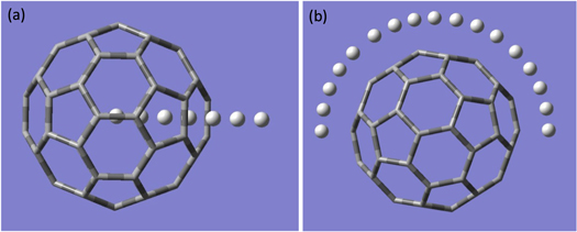
Figure 1. (a) C60 with hydrogen atoms passing through hexagonal ring for radial potential energy  scan. (b) C60 with hydrogen atoms in xy-plane for angular potential energy
  scan.
scan.
Download figure:
Standard image High-resolution image3.2. The angular potential 

Keeping the H atom fixed at a radial distance, we perform another potential energy scan with varying angular coordinate (θ) of the H atom, as shown in figure 1(b). An azimuthal plane is chosen, in which H covers equal number of hexagonal and pentagonal rings on the way of angular scanning. For the angular co-ordinate scan, same basis set and functional were used as in the radial scan. Using the obtained optimized structure of the C60, potential energy scan is performed by fixing the radial distance at 9.2628 a.u. (4.9 Å) (in xy-plane) and varying angle of the H atom from 0 degree to 180 degrees in 180 steps of step size 1 degree. The locus of the H atom is fixed in the xy-plane just outside the cage of C60.
Total potential  given in equation (5) assumes a decoupling of radial and polar co-ordinate dependence of the total potential. The linear expansion of interaction potential in terms of angular momentum quantum number
  ensures that the radial potential will be scaled to give an effective interaction potential for each partial wave. In other words, the anisotropy induces a scaled radial average potential for each partial wave. Further, the use of the scaled potential brings in anisotropic effects on the elastic scattering process.
4. Results and discussion
4.1. The interaction potential
Figure 2 shows the H-C60 interaction potential obtained in the co-ordinate scan. Left panel of the figure 2 exhibits the radial interaction potential of H-C60 case when H atom passes through the center of hexagonal and pentagonal rings and their average. The potential and the difference in its barrier maximum in the two cases (hexagon and pentagon) is in fair agreement with the work of T. T. Vehvilailen et al [25]. The barrier maximum (r ∼ 7 a.u.) occurs at a radial distance close to boundary of C60 shell. The potential has a shoulder at a radial distance of nearly 4 a.u. After a distance of 11 a.u., the potential becomes very small and tends to zero, as if the projectile and target are not interacting. The H-C60 scattering dynamics with H passing through the hexagonal and pentagonal rings is studied and contrasted in our earlier work [14]. An average of the radial interaction potential (Green curve in left panel of figure 2) corresponding to the H-C60 interaction through hexagonal and pentagonal ring is considered in this work as the radial potential  This is quite justifiable as an azimuthal plane is chosen for finding the anisotropy where equal number of hexagons and pentagons are positioned. This process of averaging radial potential increases barrier height relative to the hexagonal case and decreases relative to the corresponding pentagonal case. To systematically compare the effects of anisotropy, a calculation is performed using isotropic potential also. For the isotropic case, we employed average of the radial potential
  in the hexagonal and pentagonal case and used in equation (13).

Figure 2. The H-C60 interaction potential with varying radial distance and polar angle. Labels in the angular potential plot are described in the text.
Download figure:
Standard image High-resolution imageThe shoulder observed at r ̃ 4 a.u. in left panel of figure 2 can be explained with the help of charge density responsible for the calculated potential energy  of H-C60 interaction. The effective charge density is obtained by solving the Poisson's equation in radial coordinates for spherically symmetric potential
  in the hexagonal case, details of which is presented in an earlier work [14]. The resulting plot of charge density along with corresponding potential is shown in figure 3. One can see that
  arises due to a combined presence of characteristic positive and negative charge densities throughout the entire radial distance. At the location of the shoulder, a local maximum of positive charge density peaked at nearly r ∼ 4 a.u. is seen, which is immediately followed by a local minimum of negative density, combined resulting into such a peculiar shoulder-like structure in the interaction potential. The positive and negative charge densities can be attributed to nuclear and electronic charge distributions of the C60 molecule respectively, which the incoming projectile, H, encounters. Note that the effective charge density is plotted in figure 3, which is the net charge at a radial distance after taking into account the nodal structure of the molecular electronic orbitals. Barrier maximum of H-C60 interaction is caused by positive charge density maximum, which is centred nearly at the C60 radius (6.7173 a.u.), and vanishes at outer radius of the cage.

Figure 3. Radial charge density corresponding to spherically symmetric H-C60 potential V(r) when H atoms interacts through center of the hexagonal ring of the C60 molecule [14]. The corresponding interaction potential is shown on right side y-axis.
Download figure:
Standard image High-resolution imageThe right panel in figure 2 shows the angular variation of the H-C60 interaction in an azimuthal plane. Since the plane is chosen with equal number of hexagonal and pentagonal rings, the potential is symmetric about  = 90°. The potential figure exhibits number of minima and maxima identified at certain critical angles, which are labelled as 1–8 in the
  figure. To systematically analyse these features, figure 4 shows an illustration of Hydrogen atom at different critical angles when the projectile is making an in-plane scattering at φ = 0. Note that the H atoms are not making any bond with the C atoms; a vertical connecting link between H and C60 is just as a guide for eye to locate them. The Hydrogen atoms in figure 4 are labelled consistently with the labels of critical angle locations in figure 2. The scan starts from a position above double bond (Hydrogen atom labelled as 1 in figure 4). The first minimum in the plot at nearly 10° corresponds to the H atom above Carbon atom. The peak at ∼30° reflects the angular location of H at the centre of pentagonal ring. The minimum next to it at ∼50° is when the H atom is above single bonded C atoms. The next minimum between two small peaks (when H atom is at the two terminal ends of hexagonal ring) signifies the angular position of H atom above the centre of hexagonal ring. The central minimum at 90° corresponds again to the H atom located above the double bond between C atoms. From the angular scan, we understand that the centre of pentagon has a higher potential than the respective hexagon centre. The lower potential value of hexagon case shows that it is more stable/symmetric due to its particular orientation inherent to C60 structure. In the same context, the pentagon case is less symmetric and hence has a higher potential value. A consistent trend is reflected in the radial potential scan also: the centre of pentagonal ring is at a higher potential than that of a hexagonal ring.

Figure 4. H atom above the C60 surface in azimuthal symmetry at critical angle locations. Labels of the H atoms are consistent with that of specific angle locations in figure 2, where maxima/minima occur.
Download figure:
Standard image High-resolution imageIn order to investigate the structural features of the  the natural bond orbital (NBO) calculations have been performed using NBO 3.1 [47], which is included in Gaussian 16 [42] program package. For maintaining the consistency, level of calculation of NBO analysis is kept the same as that of potential energy scan i.e., employing DFT/B3LYP method with the basis set 6–31 g* (6d, 10f). These calculations have been performed in order to understand the interactions between carbon atoms of C60 and Hydrogen atom when placed at different locations in an azimuthal plane. NBO analysis is an efficient method to study inter- and intra-molecular interactions and their bonding properties. In addition, it gives information about charge transfer in a molecular system. Quantification of delocalization between donor (i) and acceptor (j) is feasible through NBO analysis using a mathematical formula for stabilization energy, E (2). This stabilization energy, given in kcal/mole, gives the extent of delocalization. Table 1 shows the stabilization energy E (2) and donor-acceptor orbital type of the H-C60 interaction when H atom is at critical angle locations above the C60.
Table 1. NBO analysis of H-C60 system.
| Donor NBO (i) | Bond Type | Acceptor NBO (j) | Bond Type | E (2) (kcal/mole) |
|---|---|---|---|---|
| C 9 | LP | H 1 | Vacant orbital (LP*) | 618.13 |
| C14 | LP* | H 1 | Vacant orbital (RY*) | 0.90 |
| C23-C13 |

|
H 3 | Vacant orbital (LP*) | 0.98 |
| C13-C14 |

|
H 3 | Vacant orbital (LP*) | 1.04 |
| C14-C25 |

|
H 3 | Vacant orbital (LP*) | 1.03 |
| C25-C24 |

|
H 3 | Vacant orbital (LP*) | 0.98 |
| C24-C23 |

|
H 3 | Vacant orbital (LP*) | 0.95 |
| C24 | LP | H 4 | Vacant orbital (LP*) | 86.52 |
| C23 | LP | H 4 | Vacant orbital (LP*) | 90.28 |
| C22-C23 |

|
H 5 | Vacant orbital (RY*) | 0.07 |
| C22-C23 | π | H 5 | Vacant orbital (RY*) | 0.13 |
| C22-C36 |

|
H 5 | Vacant orbital (RY*) | 0.03 |
| C23-C24 |

|
H 5 | Vacant orbital (RY*) | 0.21 |
| C24-C34 |

|
H 5 | Vacant orbital (RY*) | 0.07 |
| C24-C34 | π | H 5 | Vacant orbital (RY*) | 0.15 |
| C34-C35 |

|
H 5 | Vacant orbital (RY*) | 0.03 |
| C22-C23 |

|
H 6 | Vacant orbital (RY*) | 0.06 |
| C22-C23 | π | H 6 | Vacant orbital (RY*) | 0.03 |
| C22-C36 |

|
H 6 | Vacant orbital (RY*) | 0.07 |
| C23-C24 |

|
H 6 | Vacant orbital (RY*) | 0.07 |
| C24-C34 |

|
H 6 | Vacant orbital (RY*) | 0.06 |
| C24-C34 | π | H 6 | Vacant orbital (RY*) | 0.03 |
| C34-C35 |

|
H 6 | Vacant orbital (RY*) | 0.07 |
| C34-C35 |

|
H 6 | Vacant orbital (RY*) | 0.05 |
| C22-C36 |

|
H 7 | Vacant orbital (RY*) | 0.09 |
| C34-C35 |

|
H 7 | Vacant orbital (RY*) | 0.09 |
| C35-C36 |

|
H 7 | Vacant orbital (RY*) | 0.23 |
| C36 | LP | H 7 | Vacant orbital (RY*) | 0.33 |
| C35 | LP | H 8 | Vacant orbital (LP*) | 188.77 |
| C36 | LP | H 8 | Vacant orbital (LP*) | 183.88 |
In the right panel of figure 2, at ∼10° from the initial position of scan exhibits a lowest potential energy which corresponds to the H atom (numbered 2 in figure 4) placed above C14. At this angular location, the hydrogen atom is no longer a separate entity of this system (C60-H), and a strong interaction exists between C14 and H2. Moreover, E (2) was not calculated for this interaction, as it needs both donor and acceptor units. Scan starts with H atom (numbered 1 in figure 4) above C9-C14 double bond. In this position, stabilization happens through donation of lone pair electrons to 1-center vacant orbital of H atom from C9 (as shown in table 1). But this interaction is not as strong as the former case (H2 above C14), therefore it is at a higher potential relative to the other. Further, at ∼50°, hydrogen atom (numbered 4 in figure 4) is located above the C24-C23 single bond. Here a significant amount of delocalization from lone pairs of both carbon atoms into 1-center vacant orbital of hydrogen atom is visible from table 1, which is reflected in the enhanced stabilization energy. At ∼90°, hydrogen atom (numbered 8 in figure 4) is placed above double bond (C35-C36) and having a high stabilization energy much akin to that corresponding to H1 atom case. At ∼30° as hydrogen atom (numbered 3 in figure 4) reaches the centre of the pentagonal ring, interaction energy E (2) is very low from all the five C atoms of pentagonal ring resulting in a higher potential relative to other cases. This is probably due to absence of π-electron cloud in the pentagonal ring. At a lower potential than the pentagonal ring case, two small peaks and a local minimum appears when hydrogen atom (numbered 5, 6 and 7 in figure 4) is shifted from one terminal end to other terminal end of hexagonal ring. The interaction energy E (2) is very low for these cases also. The local minimum occurs when H atom is situated exactly at the centre of hexagonal ring probably due to the effect of π-electron cloud of hexagonal ring. Two terminal ends do not receive an appreciable amount of electron density and resulted in higher potential energy. NBO analysis did not give satisfactory results to explain these subtle variations when passing over the hexagonal ring, but an overall picture is quite clear. A similar trend follows after 90° due to symmetry. The aforementioned analysis shows that the minima and maxima are indicative of the relative interactions; minima locations in the  plot (labelled as 4 and 8 in figure 2) correspond to the increased attraction between H and C atoms mediated by the sharing of lone pair electrons from latter. On the other hand, when the H faces the pentagonal or hexagonal ring of the C60, the delocalized electrons from the ring is absent. Consequent to this, the interaction is less attractive relative to the cases when H is above C atoms and therefore a peak is visible in
The  is expanded in terms of the Legendre polynomial as given in equation (5). Left panel of figure 5 shows the absolute value of the angular expansion coefficients
  The L values contributing predominantly in the expansion are L = 0, 2, 6, 8, 12, 14 and 18 as evident from figure 5. The dominance of certain L values in angular expansion of potential with Ih symmetry is reported in the earlier works [18, 48]. The anisotropy is introduced in the calculation by making use of scaled radial potential
  which is shown in right panel of figure 5. The inset shows the isotropic interaction potential for a comparison. Thus, the effect of anisotropy is encoded in these scaled radial potentials for each partial wave. The isotropic term (ℓ = ℓ' = L = 0) dominates the interaction, which hints that the isotropic part dominates the non-isotropic part.

Figure 5. Absolute value of angular expansion coefficients CL with their angular momentum quantum number L (0 to 30) (Left panel) and the effective radial potential due to anisotropy (right panel) for different partial waves.
Download figure:
Standard image High-resolution imageAs ℓ increases the effective radial potential is scaled to lower values, thus expecting a shift of resonant energies to much lower energy values. It is well known that the resonances are sensitive to the shape and barrier height of the potential [49]. This shift in the resonant energy will be the primary indication of anisotropy on the resonances. Such scaled effective potential is reported in anisotropic potential case and its decisive effect on the positions and characteristics of scattering resonances is seen in the work of Ayelet Klein et al [7]. This is one of the prominent effects of anisotropy, implications of which will be seen in the forthcoming sections.
4.2. Total and partial scattering cross section
Figure 6 shows the comparison of total cross-section in the resonant energy range in the isotropic and anisotropic case. The anisotropy affects the scattering of collision partners to an appreciable extent. The inset in the figure 6 shows the contrasting differences in the glory oscillations in the low-energy region. Anisotropy mixes states with particular ℓ value with different L values, which results in smoothed out glory oscillations. From the left panel of figure 6, it is clear that anisotropic scattering cross-section in the low-energy region is modulated with resonances due to the C60 barrier. In contrast, the isotropic cross-section in the low-energy region is free from resonances. The resonant region in the isotropic case is spanned between 0.15 a.u. to 0.17 a.u. whereas the same in anisotropic case is scaled down to a region between 0.001 a.u. to 0.004 a.u. It needs to be emphasized here that the average of the radial potential in the hexagonal and pentagonal case is used for the isotropic calculation, for which the barrier maximum is ∼0.1642 a.u. It is because of that the isotropic resonant region is spanned between 0.15 a. u. to 0.17 a.u. The predominant effects of anisotropy on the cross section embodies in the modification and positioning of scattering (shape) resonances. The repositioning of the resonances in the anisotropic case can be attributed to the scaled radial potential for each partial wave. The Right panel of figure 6 illustrates the total scattering cross section in an energy range of 0.15 to 0.17 a.u. for both the anisotropic and isotropic cases. The isotropic cross-section exhibits sharp resonances in the background of glory oscillation in the energy range 0.15 to 0.17 a.u. On the other hand, anisotropic scattering shows only monotonically decreasing cross section, free of resonances and glory oscillations. Anisotropy mixes different angular momenta , because of which the glory oscillations are completely smoothed out in this range. These consequences are in line with the predictions of Ruiz et al [18], though they have not provided quantitative details of the total scattering cross section in the anisotropic case.

Figure 6. The total elastic cross section for H-C60 scattering for the cases of isotropic and anisotropic potential in the low energy region (left panel). Right panel shows a comparison of total cross sections for anisotropic and isotropic cases in an energy range of 0.17 to 0.19 a.u., which is marked as resonant region for the isotropic scattering.
Download figure:
Standard image High-resolution imageThe magnitude of the total cross section is almost same in the glory oscillation region. However, the regularity of the glory oscillations disappears and it smooths out very quickly in the anisotropic case compared to the respective isotropic case. The anisotropy thus is predominantly affecting the resonant cross-section compared to the background non-resonant cross-section. This justifies the use of isotropic model potentials for C60 in plethora of analysis concerning total cross-section [14, 18–21]. However, for the analysis of atom-C60 scattering resonances, the anisotropy plays a key role and hence it needs to be included for a realistic representation. The impact of anisotropy on the resonances is predicted in the earlier analysis of elastic collision of He-C60 also [18].
Figure 7 represents the partial cross section plots for anisotropic (left panel) and isotropic cases (right panel) in the respective resonant regions. A close comparison of isotropic case with our earlier work [14] demonstrates that choosing an average radial potential, makes resonant region shifted from 0.14 to 0.16 a.u. (hexagonal case) and 0.17 a.u. to 0.19 a.u. (pentagonal case) to 0.15 to 0.17 a.u. The resonances in the isotropic case are obtained for incident energies comparable to the average barrier height. In the isotropic case, the resonances occur at nearly same energy for all the even ℓ values in the case of H–C60, with their cross-sections go on increasing in their increasing order of ℓ. Likewise, the phenomenon is same for all the odd ℓ values. However, this regularity in the odd–even resonances is missing in the anisotropic case, which is again attributed to the different scaling of the effective radial potential.
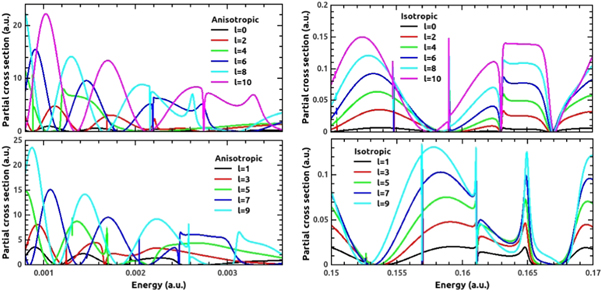
Figure 7. The partial cross section for H-C60 collision in the cases of anisotropic (left panel, top and bottom) and isotropic (right panel, top and bottom) potentials for different partial waves in their resonant energy regions.
Download figure:
Standard image High-resolution imageThe numbers of resonances are same for each partial wave in both the cases except that few resonances are too weak to resolve properly in anisotropic case. It is further clear from the comparison that the anisotropy pushes the resonances to low energy regime from corresponding intermediate energy region of isotropic case. This is very prominent feature to take into account while working with anisotropic cases for the same collision partners. A quantitative approach to analyze the resonant features is given through Fano parameterization methodology in the next section.
4.3. Fano parameterization of resonance
The anisotropic interaction changes the resonant parameters significantly. To quantify the effect of anisotropy, first resonance (labeled as R1) of the ℓ = 0–4 partial waves is scrutinized employing Fano parameterization formula. Figure 8 shows the Fano-fitted resonance R1 in the isotropic and anisotropic cases for ℓ = 0. For the R1 of the same partial wave, resonant energy  background cross section (
 ), resonant width
  and Fano shape parameter
  are evolved to quite different values. Table 2 shows the comparison of the Fano shape parameters, obtained from fitting with equations (17) and (18), for the isotropic and anisotropic cases considered for R1 resonance. Table 2 shows that the resonant energy
  is different for different partial waves in the anisotropic case in a range of 0.000 878 to 0.002 593 a.u. and in the isotropic case in the energy range of 0.15–0.17 a.u. The shape parameter
  remains negative, however the value changes from −0.90 to −1.80 due to anisotropy for ℓ = 0. For ℓ = 1, the
  parameter varies from 0.70 in the isotropic case to 1.53 in the anisotropic case. For ℓ = 2, isotropic q value is negative (−0.38) while anisotropic value is a close positive value (0.30). For ℓ = 3,
  parameter changes from 0.70 in the isotropic case to a quite large value of 7.70 in the anisotropic scattering. The last obtained
  for ℓ = 4 holds a value of −0.83 in isotropic case which approaches to a close similar value of −0.94 for the anisotropic scattering. For all the partial waves, resonances are sharper in the isotropic scattering than the anisotropic case except for ℓ = 3, which is obvious from a comparison of
  values in the Table 2. Only ℓ = 3 resonance is significantly closer in its resonant width for both the cases. Extremely closer resonant energies for even and odd ℓ values signify almost overlapped resonant structures in the isotropic scattering (as shown in the right panels of figure 7), which is not at all seen in the anisotropic case. The background non-resonant cross-section is also altered, which is due to the drifting of resonant energy to lower side upon inclusion of anisotropic effects. Fano analysis confirms that anisotropy modifies quantum scattering resonances to quite significant extent evolving each of the Fano parameters for different partial waves. A similar Fano resonance analysis can be performed for other ℓ values as well, but the consistent changes in the cross-section of the initial partial waves are indicative of the fact that the similar effects could be expected in other cases also. Moreover, the scaling of the effective interaction potential is consistent in all cases.

Figure 8. The Fano fitting for the H-C60 scattering cross-section in the anisotropic (left panel) and isotropic cases (right panel) for ℓ = 0 partial wave.
Download figure:
Standard image High-resolution imageTable 2. Fano parameters of resonances R1 in the H-C60 scattering cross section in anisotropic and isotropic cases. All quantities are in atomic unit (a.u.).
| Fano Parameters | |||||
|---|---|---|---|---|---|
| H-C60 scattering | ℓ | Er | q | Γ/2 (10−5) | σ0 |
| Anisotropic | 0 | 0.002 593 | −1.80 | 0.080 | 0.259 |
| 1 | 0.001 938 | 1.53 | 0.640 | 0.985 | |
| 2 | 0.001 686 | 0.30 | 0.050 | 1.516 | |
| 3 | 0.001 242 | 7.70 | 0.075 | 3.360 | |
| 4 | 0.000 878 | −0.94 | 0.060 | 3.950 | |
| Isotropic | 0 | 0.154 838 | −0.90 | 0.007 | 0.004 |
| 1 | 0.156 980 | 0.70 | 0.080 | 0.004 | |
| 2 | 0.154 831 | −0.38 | 0.014 | 0.020 | |
| 3 | 0.156 971 | 0.70 | 0.080 | 0.020 | |
| 4 | 0.154 816 | −0.83 | 0.008 | 0.028 | |
4.4. Differential cross section
Figure 9 shows evolution of differential cross section (DCS) when anisotropic effect is included. For contrast and comparison, the DCS is presented for four different energies (E = 0.0001, 0.001, 0.01 and 0.1 a.u.) for anisotropic and isotropic cases. The isotropic and anisotropic DCS exhibit diffraction type maxima and minima. When the projectile is scattered with a smaller energy (0.0001 a.u.), the DCS is less structured compared to the same at higher energies. In a more classical sense, this tells that with increment in energy, there is more no. of branches with different impact parameters which results into scattering at same angle. Such branches interfere mutually and hence these oscillations in high energy scattering cases.

Figure 9. The differential cross section for H-C60 scattering for different incident energies in both anisotropic and isotropic case.
Download figure:
Standard image High-resolution imageA trend is observed that the maxima and minima in the isotropic and anisotropic case happen almost at the same angles in the forward scattering regime. This observation is quite consistent with existing understanding in the e-C60 scattering and Atom-C60 scattering. An earlier work on e-C60 scattering [50] reported that the simple spherical model (isotropic) of C60 predicted the maxima and minima in the DCS in agreement with that using realistic static-exchange model in the forward scattering angles. Similar trend is noticeable in the calculations of Ruiz et al [18] in the elastic scattering of atom and C60 that anisotropy induces less change in the forward scattering angles. On the other hand, in the higher angles, both the cases differ each other. One may notice that the anisotropy mellows down some of the intermediate angle oscillations and produce more significant changes at backscattering angles. The presence of anisotropy, hence, makes these undulations different in oscillations, phase, and magnitude. A similar effect of anisotropy on differential cross sections is reported in semiclassical regime on molecular scattering in the work of R. J. Cross [51].
The magnitude of the differential cross section near forward scattering angle is more for anisotropic case at energies 0.001 and 0.1 a.u. Further, the backward scattering magnitude is significantly larger for anisotropic case for energies 0.0001 and 0.001 a.u. compared to isotropic case.
4.5. Partial phase shift and time delay
The resonant phase shift is exhibited in figure 10 and it is analyzed in light of the effect of anisotropic interaction. Signature of resonance is reflected as a π-jump for sharp ones and less than π-jumps for weaker ones. If we compare anisotropic (left panel) phases with isotropic (right panel) phases, it is observed that there is almost equal no. of jumps signifying equal number of resonances. The so-called bunching of even and odd ℓ values in our previous work [14], still exist in the isotropic case in spite of the fact that potential taken here is averaged over hexagonal and pentagonal potentials. The resonant region therefore shifts to 0.15 to 0.17 a.u. Anisotropy makes the peculiar feature of phase bunching to extinct. Moreover, in this case resonant phases are very sparsed throughout incident energy. There are prominent resonances at relatively smaller energy and it becomes less sharp as energy goes higher. This is because as energy of the projectile increases, the chance of its trapping in the C60 barrier decreases proportionally.
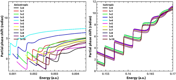
Figure 10. The resonant phase shift for H-C60 scattering in the cases of anisotropic (left panel) and isotropic potential (right panel) for ℓ = 0 to 10 partial waves.
Download figure:
Standard image High-resolution imageThe time delay for different partial waves in the anisotropic (left panel) and isotropic (right panel) potential is displayed in figure 11. Corresponding to sharp resonances, we observe peaks in the time delay profile. The even–even and odd–odd phase bunching in isotropic case results into time delay peaks at same location for the corresponding partial waves. On the other hand, anisotropy makes the peaks dispersed along the entire energy range; hence the respective time delays are seen to be quite sparsed. In addition, the peaks in the time delay are shifted to low-energy region also. An average of the time delays will decipher that the projectile spends less time in the vicinity of the C60 due to anisotropy relative to isotropic approximation. This claim is verified by analyzing the weighted average of time delay, which is defined as:

where,  is the partial cross section. Figure 12 shows the average time delay in the H-C60 scattering for the isotropic and anisotropic case. In the former case, the peaks corresponding to the different partial waves appear almost as one peak in the averaged time delay. This regularity is missing in the latter and the time delay peaks appear in scattered manner due to the differently scaled potential for different partial waves. Of importance is the observation that the average time delay is substantially reduced due to the anisotropic interaction. For instance, the maximum time delay noted in the isotropic case is 17 pico seconds, whereas the same in the anisotropic case is reduced to 4.6 pico seconds. It is to be noted that the non-resonant scattering shows negative time-delay.
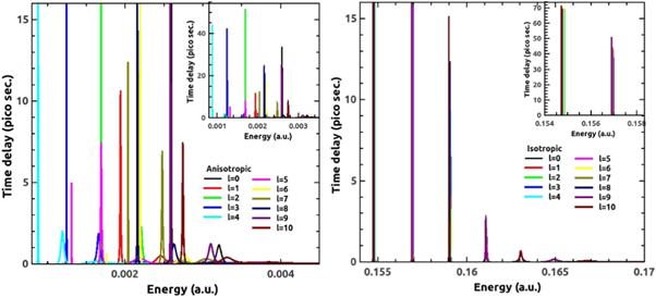
Figure 11. The Eisenbud-Wigner time delay for H-C60 scattering in the cases of anisotropic (left panel) and isotropic potential (right panel) for ℓ = 0 to 10 partial waves. The inset shows the time delay in full scale.
Download figure:
Standard image High-resolution image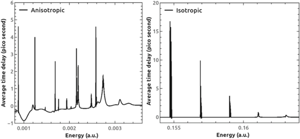
Figure 12. The weighted average time delay of H-C60 scattering for the cases of anisotropic (left panel) and isotropic potential (right panel).
Download figure:
Standard image High-resolution image
From the partial time delay figure (figure 11) we see that, for a particular partial wave, time delay is larger at smaller energies in the isotropic case. This happens because at lower energies the resonances are very sharp and prominent. Time delay goes on decreasing while width of its peak increases as the energy goes higher. This is because at higher energies the resonances become weaker and weaker. First three prominent resonances have time delay in the range 69.91 to 0.71 pico seconds (up to two decimal places) in the isotropic case. Different partial waves suffer different time delay and it goes on decreasing with the increasing value of ℓ as is clear from isotropic plot. This is so because as with increasing ℓ, the centrifugal barrier increases in proportion and keeps the projectile away from reaching the center. In the anisotropic case, a progressive change is not observed in the time delay parameters. The irregularity is due to the scaling of interaction potential due to anisotropy at different levels. The maximum time delay is observed in anisotropic case to be 50.18 pico second for ℓ = 2 partial wave and minimum 0.06 pico second for ℓ = 8 partial wave. The trend of time delay is to decrease upon anisotropic interaction of H with C60.
5. Conclusion
Theoretical investigation of the elastic scattering of H atom with C60 using an anisotropic potential is discussed here. The primary objective of the present work is to scrutinize the changes in the resonant scattering parameters upon including non-spherical terms in the Hamiltonian. Without assuming the complexity of molecular rotation and an overall estimation of various energy transfer modes through inelastic scattering, the present work explores characteristics of resonant scattering at a fundamental level. The work concludes that resonant features are substantially modified due to the anisotropy. However, the non-resonant cross section and other scattering parameters remained unaffected. This work reasserts the earlier predictions that the resonant scattering will be modified due to anisotropic interaction, but not the background cross section.
The radial and angular dependent potential is obtained employing the Density Functional Theory (DFT) using the GAUSSIAN 16 [43]. This method takes into consideration the Hartree–Fock level electron-electron interaction of the C60 shell. Till now, the studies of scattering of C60 molecules were performed with various model potentials. Not much of a stress was given to the effects of anisotropic interactions in the atom-C60 scattering except in the work of Ruiz et al [18]. The scattering study of rare gas atoms and C60 with C60 considering anisotropic form of interaction was performed in the works of Ruiz et al but with a simplified model potential. To the best of author's knowledge, it is in the present work, first time a microscopic level anisotropy is included in the interaction potential of an atom and C60 for the scattering studies. Thus, our work presents a novel and simple approach towards such studies.
It is well known that C60 supports resonances in the elastic scattering. Anisotropy shifts the resonances to quite low energy regime relative to the isotropic case. In simple terms, the presence of anisotropy scales down the effective radial potential and this averaged potential moves the resonant region to low energies. Although, isotropic behavior dominates overall, the changes occur in all resonant parameters for all partial waves considered due to anisotropy. Fano parameters of the first resonances (R1) of ℓ = 0–4 partial waves are scrutinized under the lights of anisotropy. It is seen that the Fano resonant features are considerably modified due to anisotropy. The phase shift and time delay features are qualitatively same for both isotropic and anisotropic case except that the resonances are scattered in the entire energy range. A weighted average of the time delay deciphers that the anisotropy reduces the delay in the scattering from C60. Differential cross section exhibits differences due to anisotropy especially in the backward scattering angles. This behavior is consistent with earlier observations also. Anisotropy mellows down glory resonances, which is an obvious feature in the isotropic case. Of significance is the conclusion that the non-resonant scattering cross section is almost unaffected in our analysis. This justifies the use of isotropic interaction potential in the non-resonant photoionization and scattering studies.
The present work addresses the effects of anisotropy on the resonant H-C60 scattering cross-section and hence the conclusions can be generalized for all atom-C60 scattering. A pertinent question to answer now is about anisotropic effects in the e-C60 scattering and the associated half-scattering process, photoionization from the C60. For that matter, anisotropic effects in the electron scattering and photoionization from endohedral systems (A@C60) can also be addressed. A recent ab-initio study, which takes into account all the carbon atoms in the right symmetry of the C60, has investigated the e-C60 scattering and the work found a surprising agreement with results from a spherical model potential calculation [50]. The spherical model, despite its extreme simplicity, was surprisingly successful in qualitative and semiquantitative predictions of the resonant characteristics compared to the far more elaborate ab-initio calculation with C atoms at its right symmetry [52]. Moreover, the isotropic approach was successfully used to compare with experimental cross sections on inelastic scattering of electrons from C60 [53]. These observations lead to a contradicting picture for e-C60 and atom-C60 scattering; in atom-C60 collision, the anisotropy is important as predicted not only by the present studies, but several earlier works also [18, 48, 51], whereas the e-C60 scattering is predominantly isotropic. We agree with this contradiction as the e-C60 resonances are supported by the angular momentum barrier; the effect of C60 is appearing as an attractive spherical well in the e-C60 interaction potential [54, 55]. On the other hand, the atom-C60 resonances are supported by the barrier caused by the C60 itself [14]. In effect, the C60 is offered as a barrier in the atom-C60 interaction [14, 25]. Therefore, the anisotropy coming from the hexagonal and pentagonal rings clearly affects the C60 barrier and hence the scattering resonance will be amply modified. In the e-C60 scattering, the angular momentum barrier is dominating the attractive spherical well and therefore the barrier causing the shape resonance is fairly unaltered even after the inclusion of anisotropy. Hence the conclusions of the present work can be generalized for atom-C60 scattering, not for e-C60 scattering or photoionization.
The notion that the whole anisotropic character can be encoded through the scaled isotropic potential (radial potential) is a unique conclusion of the present work. This will lead to new ways of treating anisotropy in far simplest forms. Although azimuthal symmetry assumed in this work is rather simplistic, the approach correctly delivers effects of anisotropy on resonant parameters. Inclusion of azimuthal anisotropy may bring some more changes. To conclude, this work wraps up with unique and crucial results, which show the dramatic effects of anisotropy on resonant scattering.
Acknowledgments
JJ and AD acknowledge the support provided by SERB through the project no. –ECR/2016/001564.
TRR acknowledges DST for the project under INSPIRE Faculty Award –DST/INSPIRE/04/2015/000094.