

Abstract
3D hemispherical protruded micro features find wide application in various fields of surface engineering viz. micro lens let arrays, solar cells, energy conversion devices, heat transfer applications, tribological applications and many more. The present authors have already devised a technique for generating 3D hemispherical protruded micro feature by suitable tool modification in reverse micro EDM. In this paper, the microstructural and mechanical characterization of the already generated 3D hemispherical protruded micro feature is studied in order to determine the extent of the formed recast layer, heat affected zone (HAZ) and their mechanical properties viz. hardness, elastic modulus and residual stress in comparison to the parent material. Results indicate that the recast layer has higher hardness and elastic modulus followed by the hardened layer of HAZ as compared to the parent material. The soft layer of HAZ has the least hardness and elastic modulus. Qualitative analysis of residual stress using the loading and unloading portion of the load-displacement curves indicate that the recast layer has compressive residual stresses while the soft layer of HAZ has tensile residual stresses.
Export citation and abstract BibTeX RIS
1. Introduction
3D hemispherical protruded micro features find wide application in various fields of surface engineering viz. tribological, micro lens let arrays, solar cells, energy conversion devices, heat transfer applications and many more. Bhattacharjee et al [1] studied the DLVO (Derjaguin-Landau-Verwey-Overbeek) interaction potential on a surface considering both hemispherical protrusion as well as depression to model an actual rough surface. Surface element integration technique showed that repulsive interaction energy reduces significantly which depends on the size and frequency of the hemispherical protrusions and depressions. Zhang et al [2] developed a super hydrophobic surface with water contact angle 163° using hemispherical protruded micro features using ZnAl-LDH-laurate hybrid film on substrate. Structural integrity and hydrophobicity led to good corrosive properties of the film which sustained longer immersion period (31 days) in 3.5% NaCl solution at room temperature without any structural changes. Il'inkov et al [3] experimentally studied the heat transfer on a surface with hemispherical protrusions at the turbulent flow regime. Results showed that by increasing the number of hemispherical protrusions upto a certain point (ratio of the total surface area with hemispherical protrusions to the area of surface without protrusions = 0.24), the average heat transfer increases; while increasing the number of hemispherical protrusions beyond that point, the average heat transfer gradually decreases. Yadav et al [4] enhanced the heat transfer and friction factor during turbulent flow of air through a rectangular duct containing hemispherical protrusions as compared to a smoot duct. Li et al (2014) found that by incorporating low aspect ratio micro/nano hemispherical protrusions on ultrathin GaAs solar cells, light can be absorbed higher than 90% in regime of high photon energy density of the solar spectrum for GaAs. Li et al [5] carried out experimental studies to understand the effect of hemispherical protrusions on absorber plate for predicting heat transfer and flow characteristics of solar air collector duct. Results showed that the heat transfer enhanced considerably as compared to smooth surface. Hemispherical protrusions were also found to have a substantial effect on Nusselt number and friction factor. Liu et al [6] performed numerical investigations to determine the effect of hemispherical protrusions on flow and heat transfer in dimpled cooling channels. The averaged local heat transfer of dimpled surface was greatly increased due to the hemispherical protrusions that were place ahead of the dimples. Also, these hemispherical protrusions caused downward flows and thereby helped in reducing the extent of recirculating flows in the dimples.
Literature survey indicates that incorporating hemispherical protrusions on the surface enhances the surface properties required for various applications described above. Though a lot of work has been carried out for generating these hemispherical protruded micro features, certain aspects of these protrusions viz. microstructural and mechanical properties characterization that gives an indication of the life of these protrusions are yet to be studied. The present authors have already devised a technique for generating 3D hemispherical protruded micro features using tool modification in reverse micro EDM [7]. The details of fabrication technique are described in brief in section 2.1. In this paper, micro structural and mechanical characterization of the 3D hemispherical protruded micro feature has been carried out. This includes identifying and locating recast layer and heat affected zone (HAZ) that are inevitable in discharge based machining processes and their mechanical properties in comparison to parent material viz. loading-unloading curves, hardness, elastic modulus and residual stresses.
2. Materials and methods
2.1. Experimental procedure
Conventional RMEDM with tool in the form of a through hole on plate (cathode) generates a 2.5D cylindrical protruded micro feature on anode. In order to generate a single 3D hemispherical protruded micro feature using RMEDM, modification in tool is required. A pre-drilled tapered blind hole on plate (cathode) was employed as tool. The dimension of the tapered blind hole was one of the most important factors in shaping of 3D hemispherical protruded micro feature. The depth of drilled hole was kept equal to its radius. Apart from the hole dimensions, other important factors that contributed towards shaping of 3D hemispherical protruded micro feature were the debris adhesion and agglomeration on the electrodes which contributed in a constructive manner as opposed to the general trend followed by researchers where debris adhesion and agglomeration are considered to be hindrance to machining in case of discharge based machining processes.
Material selection for both tool and workpiece was critical since higher erosion on workpiece was desired while minimal wear on blind tapered hole was required for maintaining shape integrity of the 3D hemispherical protruded micro feature. The material for shaping of 3D hemispherical protruded micro feature was selected as brass since it erodes more while material for tool was selected as stainless steel (grade AISI 304) which has a lesser wear ratio as compared to brass.
figure 1(a) shows the schematic of RMEDM process with modified tool and figure 1(b) shows the actual fabricated 3D hemispherical protruded micro feature. Table 1 shows the parameters used during experiments. Initial experiments were performed and optimised to establish these parameter levels.
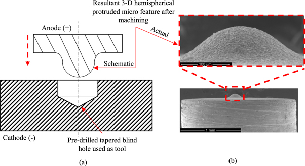
Figure 1. (a) Schematic of RMEDM with modified tool (b) Actual 3D hemispherical protruded micro feature.
Download figure:
Standard image High-resolution imageTable 1. Operating Parameters.
| Parameters: | Values | Parameters | Values |
|---|---|---|---|
| Open circuit voltage | 125 V | Capacitance | 1000 pF |
| Discharge pulses | RC circuit | Electrode feed rate | 2 μm/sec |
| Return time | 100 μsec | Hold time | 100μsec |
| Sensitivity | 30% | Diameter of hole | 0.2 mm |
2.2. Sample preparation
Sample preparation was carried out with extreme care as moderate amount of pressure may lead of breakage or chip off of the 3D hemispherical protruded micro feature. A polymeric transparent mould was mounted on the sample using Citopress-10 (figure 2) for holding and polishing was carried out using Tegra Doser-1. Polishing was carried out till the internal structure of the micro feature was visible using optical microscopy. Finally, the samples were etched in concentrated nitric acid solution for approximately 5 s in order to reveal the micro structure for further characterization.
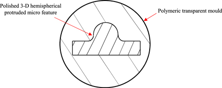
Figure 2. Polished 3D hemispherical protruded micro feature mounted on polymeric transparent mould.
Download figure:
Standard image High-resolution image2.3. Characterization techniques
Imaging of fabricated 3D hemispherical protruded micro feature was done using SEM. To visualise the grain structure clearly after metallography, electron back scattered diffraction (EBSD) was employed. Nano indentation tests were performed on the polished workpiece to determine the load-displacement curves, hardness and elastic modulus of the recast layer and heat affected zone as compared to the parent material. Also, qualitative analysis of residual stresses was carried out based on loading and unloading curves.
3. Results and discussion
3.1. Microstructural characterization and determination of recast layer thickness
Figure 3 shows the grain structure of the 3D hemispherical protruded micro feature after etching. The voids (black in colour) are the etching pits that were formed during processing of the 3D hemispherical protruded micro feature. The top portion shows the region where discharges occurred leading to shaping of micro feature. The bottom portion depicts the region where no discharges occurred. Debris adhesion and agglomeration during machining resulted in numerous abnormal discharges (secondary (debris-electrode interaction) and higher order (debris-debris interaction) discharges) leading to shaping of 3D hemispherical protruded micro feature [7]. These discharges, however, affects only the surface as they lead to variation in size of craters which eventually affects the surface roughness at different locations on the micro feature [8].
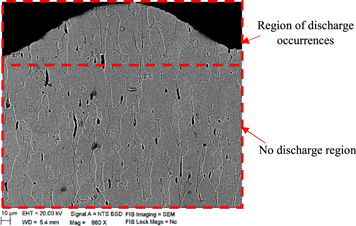
Figure 3. EBSD imaging of 3D hemispherical protruded micro feature revealing the entire grain structure.
Download figure:
Standard image High-resolution imageIn any discharge based machining process, formation of recast layer is inevitable. This layer has different properties as compared to the parent material [9]. Hence, determination of thickness of recast layer is extremely important from the point of view of application of the generated 3D hemispherical micro feature. A portion of the surface of generated micro feature is shown in figure 4. Craters formed due to millions of discharges during machining are also accompanied by re-solidified molten material deposited on the surface and agglomerated debris that adhere to the surface. The presence of these results in the formation of recast layer on the surface. Figure 5 shows the schematic of a single crater with re-solidified molten material and agglomerated debris adhered to the surface. The recast layer thickness can be described as the combination of re-solidified molten material thickness and the thickness of agglomerated debris as shown in figure 5. Since, discharge energy in this case is very low (7.8 μJ), it leads to a very small amount of material removal from the surface after every discharge. Due to this, adverse effects on surfaces viz. cracks, voids etc which are common in macro EDM are absent in this case. Grain structures in the top portion as well as bottom portion of figure 3 are quite similar.
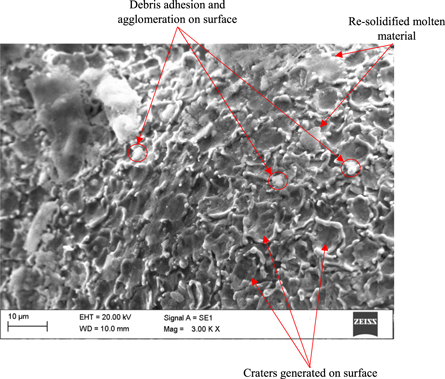
Figure 4. A portion of surface of generated micro feature.
Download figure:
Standard image High-resolution image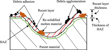
Figure 5. Schematic of recast layer and HAZ in a single crater.
Download figure:
Standard image High-resolution imageRecast layer on the 3D hemispherical protruded micro feature was found out from magnified EBSD images of top portion of figure 3 and is shown in figure 6. At the periphery of the micro feature, both near the tip as well as the base, a thin layer of re-solidified molten material (recast layer) is clearly observed. This layer is extremely small as compared to traditional EDM process where recast layer is of the order of 20–40 μm [10–12]. Due to comparatively smaller amount of discharge energy, smaller amount of material on the surface gets affected by the discharges resulting in smaller amount of recast layer. To determine the variation of recast layer from the tip to the base of micro feature, a total 15 measurements were carried out to find the thickness of recast layer. Figure 7 shows the recast layer thickness at all the 15 different locations on the 3D hemispherical protruded micro feature. Thickness of recast layer was measured by using public domain image processing software (ImageJ 1.46r, NIH). The maximum value of recast layer was found near the base (2.7 μm) while the least value was observed near the tip (1.3 μm). The average recast layer thickness was found out to be 1.8 μm.
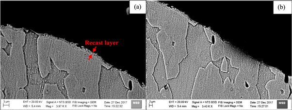
Figure 6. EBSD imaging of 3D hemispherical protruded micro feature (a) Near the tip (b) Near the base.
Download figure:
Standard image High-resolution image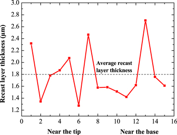
Figure 7. Recast layer thickness on 3D hemispherical protruded micro feature.
Download figure:
Standard image High-resolution image3.2. Mechanical properties of recast layer and heat affected zone (HAZ)
The schematic in figure 5 also shows the HAZ which is beneath the recast layer. Nano indentation was carried out on the polished 3D hemispherical protruded micro feature specimen. This was done to determine the HAZ on the micro feature as there was no significant effect of HAZ on the microstructure observed from figures 3 and 6. Hence, the location of HAZ was identified by comparing the hardness values obtained from nano indentation tests with that of the parent material as well as the recast layer. Apart from hardness, elastic modulus was also determined for the recast layer and the HAZ. Determination of these mechanical properties helps is estimating the life expectancy of these micro features particularly in tribological applications. To obtain this, a total of 18 nano-indents were performed on sample. Figure 8 shows the schematic of 1 set of nano-indents (N1-N6) that were made to determine the mechanical properties viz. hardness and elastic modulus of recast layer and HAZ. Moreover, a total of 6 nano-indents were also made at random locations on the parent material (bottom portion of figure 3) that is far away from discharge location in order to know its mechanical properties and use it for comparison with that of recast layer and HAZ. N1 is made on the recast layer and is near to the periphery whereas N6 is nearer to the centre of the fabricated 3D hemispherical protruded micro feature. The indents were made at a gap of 5 μm each. Indentations were performed in the depth control mode with a maximum depth of 200 nm.
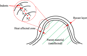
Figure 8. Schematic of 3D hemispherical protruded micro feature showing the location of nano indents.
Download figure:
Standard image High-resolution imageTypical loading-unloading curves for parent material and nano-indents N1 and N6 have been plotted and shown in figure 9. It can be seen that loading-unloading curve for N1 has higher loading values and lower final displacement as compared to parent material. The loading-unloading curve for N6 is similar to the parent material confirming that it is unaffected by the discharges and forms a part of the parent material. Hence, indentations were limited to 6 for each case since N6 shows the behaviour of parent material.
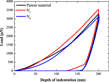
Figure 9. Loading and unloading curves for nano-indents made on parent material, recast layer (N1) and near the centre (N6) of the fabricated 3D hemispherical protruded micro feature.
Download figure:
Standard image High-resolution imageNano-indentation helps in determining the hardness, and modulus of elasticity,
 of the recast layer and HAZ as compared to the parent material. The following formulas are used for finding out
  and
and  [13].
[13].


Where,  peak indentation load,
  projected area of the hardness impression,
  contact stiffness,
  hardness,
  reduced modulus of elasticity with consideration of the effect of non-rigid indenters,
  Poisson's ratio and elastic modulus of material,
  Poisson's ratio and elastic modulus of Berkovich indenter.
Based on equations (1)–(3), hardness and elastic modulus have been calculated and shown in figures (10–11) respectively. Referring to figure 10, the average hardness of the parent material has been found out to be 3.2 GPa. Localized heating of surface during discharge results in melting and vaporization leading to removal of small amount of material from the workpiece. Most of the molten material, however, re-solidifies and settles on the surface. Due to very short pulse on and off times during machining in RMEDM (of the order of tens of ns), there is a possibility of quenching on the surface that leads to formation of recast layer. Due to this, a hardened recast layer is formed which can be confirmed based on higher hardness values of recast layer (N1) as compared to the parent material. The quenched zone is still present a little distance away from the recast layer as indicated by the higher hardness value (N2). This marks the onset of HAZ which is composed of two layers (a) hardened layer and (b) annealed layer [14]. N2 denotes the hardened layer of HAZ, which is followed by a steep decline in hardness (N3) at a distance of around 10 μm from the periphery. In this zone, relatively slower cooling of material takes place that leads to formation of soft layer with a lower hardness as compared to the parent material. The soft layer of HAZ extends to a length of approximately 10 μm (N3, N4) beyond which the material starts regaining its original hardness (N5). The hardness at a distance of around 30 μm from the periphery (N6) is approximately similar hardness as the parent material indicating that this zone in unaffected by the discharges.
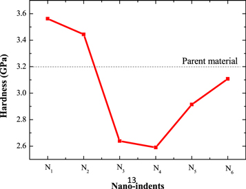
Figure 10. Variation of hardness on the fabricated 3D hemispherical protruded micro feature.
Download figure:
Standard image High-resolution image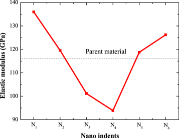
Figure 11. Variation of elastic modulus on the fabricated 3D hemispherical protruded micro feature.
Download figure:
Standard image High-resolution imageDuring the unloading process, the load will be reduced at a constant rate. Pure elastic recovery occurs in this process. The reduced elastic modulus (equation (2)) can be correlated to the slope of the displacement-unloading curve. Elastic modulus for recast layer, HAZ and parent material were determined using equation (3). The resulting elastic modulus for nano indents (N1-N6) is shown in figure 11. A horizontal line depicts the elastic modulus of the parent material.
Recast layer formation (N1) leads to substantial increase in the elastic modulus as compared to the parent material. Beyond the recast layer, there is a reduction in elastic modulus of the hardened layer of HAZ (N2) and is close to that of the parent material. This decrease in elastic modulus from the recast layer to the hardened layer of HAZ is also observed for hardness (figure 10) [15, 16]. The elastic modulus reduces further for the soft layer of HAZ (N3, N4). This variation in HAZ primarily arises due to adjacent hardening and softening of material due to discharge leading to reduced elastic modulus in the soft layer. Beyond the HAZ, the material regains the original properties of the parent material.
Based on the above discussion, the recast layer, hardened layer and soft layer can be demarcated from the parent material as shown in figure 12. The thickness of each layer along with the height of micro feature is also indicated. The recast layer has the highest hardness and elastic modulus while the softened layer of HAZ has the least of all. The properties of parent material are intermediate between the two.
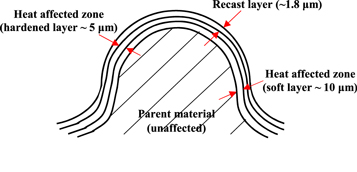
Figure 12. Schematic of 3D hemispherical protruded micro feature showing the recast layer, hardened and soft layer of HAZ.
Download figure:
Standard image High-resolution image3.3. Residual stress
A qualitative comparison of residual stresses between the recast layer and heat affected zone with that of parent material is carried out based on loading and unloading curves obtained from nano indentation tests. Load-displacement curves are significantly affected by the presence of residual stresses in the material. For same penetration depth (200 nm in this case), higher loading values as compared to parent material indicates increase in compressive stresses whereas decrease in load indicates presence of tensile stresses. Figure 13 shows the effect of residual stress on loading curves for nano-indents N1-N6 as compared to the parent material. Recast layer (N1) and hardened layer of HAZ (N2) exhibits some amount of residual compressive stresses as the amount of load required for penetrating 200 nm is higher as compared to parent material. Residual compressive stresses constrain the indentation plasticity [17] and hence, higher loads are required for indentation as compared to parent material. High hardness on recast layer is due to presence of compressive residual stresses [18]. Soft layer of HAZ (N3-N4), on the other hand, exhibits tensile residual stress, since, the amount of load requirement for same penetration is lower as compared to parent material. Hence, the hardness of soft layer of HAZ is also low. The presence of tensile residual stress enhances the indentation plasticity as compared to parent material [17] and hence, lower loads are required. Beyond N4, the material starts regaining its original strength as the loading curves (N5- N6) are shifted towards that of parent material.
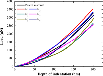
Figure 13. Loading curves for indents made to a maximum depth of 200 nm with different residual stress states.
Download figure:
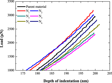
Standard image High-resolution imageThe presence of residual stress can also be confirmed based on unloading curves of material obtained from nano-indentation tests. The unloading curves undergo pure elastic recovery and no plastic recovery takes place [19]. The ending part of unloading curves (N1- N6) is shown in figure 14. With respect to parent material, the unloading curves for recast layer (N1) and hardened layer of HAZ (N2) shift towards left. Since, presence of residual compressive stresses tend to lift the indenter higher as compared to parent material, more elastic recovery and smaller residual depths are induced in the recast layer. Corresponding to unloading curves for soft layer of HAZ (N3- N4), an opposite effect i.e. lesser elastic recovery and larger residual depth is obtained indicating a tensile residual stress in this layer as compared to parent material.
Figure 14. Ending part of unloading curves for indents made to a maximum depth of 200 nm with different residual stress states.
Download figure:
Standard image High-resolution image
4. Conclusions
In this study, mechanical and microstructural characterization of 3D hemispherical protruded micro feature generated by reverse micro EDM (RMEDM) has been studied. The following conclusion can be derived from this study.
- No adverse effect was observed on the internal grain structure of the 3D hemispherical protruded micro feature and it remains uniformly distributed. However, a very thin layer of re-solidified molten material (recast layer) is uniformly formed around the periphery of the micro feature.
- Determination of hardness from the periphery to the centre of micro feature led to identification of hardened and soft layer of heat affected zone (HAZ). The recast layer had the highest hardness followed by the hardened layer of HAZ. The soft layer had the least hardness as compared to parent material.
- Elastic modulus of recast layer, hardened and soft layer of HAZ were determined using the slope of the unloading curve. Recast layer formation substantially increased the elastic modulus as compared to parent material. The soft layer of HAZ had the least elastic modulus.
- Qualitative analysis of residual stress using the loading and unloading portion of the load-displacement curves indicated that the recast layer comprises of compressive residual stresses while the soft layer of HAZ had tensile residual stresses as compared to the parent material.
Acknowledgments
T Roy is grateful to Dr K V Mani Krishna and Mr N Keskar, MMD, BARC for helping out with EBSD characterisation. The authors also acknowledge Prof P Pant, IIT Bombay for allowing us to use the nano indentation facility at their laboratory.
Funding source
This research did not receive any specific grant from funding agencies in the public, commercial, or not-for-profit sectors.