
Abstract
We propose a digital holographic microscope for the single-shot multicolor three-dimensional (3D) image sensing of specimens illuminated by spatially and temporally incoherent white light. The proposed microscope exploits self-interference, single-shot phase-shifting incoherent digital holography, a polarization-imaging color image sensor, and static polarization-sensitive optical elements to generate two object waves with different curvature radii. The microscope does not require any spatial light modulator or a beam splitter, and can be constructed with a compact single-path optical setup. The color holographic 3D motion picture recording of spatially and temporally incoherent white light at a speed of 10 fps order is experimentally demonstrated with the proposed microscope.
Export citation and abstract BibTeX RIS

Original content from this work may be used under the terms of the Creative Commons Attribution 4.0 license. Any further distribution of this work must maintain attribution to the author(s) and the title of the work, journal citation and DOI.
1. Introduction
Computational microscopy has contributed to the multidimensional image sensing of specimens by employing a mathematical method [1–5]. Three-dimensional (3D) microscopy without mechanical scanning has been realized by utilizing both physics and digital signal processing. Digital holographic microscopy (DHM) [6] is becoming a promising type of computational 3D microscopy based on the combination of holography and digital signal processing. Quantitative 3D image information is recorded as a digital hologram and reconstructed with a computer by calculations based on wave optics. Computational 3D imaging based on digital holography (DH) [7–9] has led to the developments of 3D motion picture microscopy [10, 11], mechanical-motion-free multidimensional microscopy [12, 13], and quantitative phase tomographic imaging [14–16]. However, general DHM requires a coherent light source to record an interference fringe image.
Incoherent DH [1, 17–36] is a technique of obtaining a digital hologram with spatially incoherent light and observing the 3D distribution of multiple spatially incoherent light sources based on holography. This technique has been applied to fluorescence 3D microscopy [17, 19, 25–27], 3D imagery using a common light source [18, 21, 23], 3D image measurement of thermal radiation [24], and super-resolution imaging with Fresnel incoherent correlation holography (FINCH) [25–27]. Incoherent DH techniques have also been applied to recording of multiwavelength 3D images [13, 18, 27–30]. Multiple-wavelength information in incoherent DHM enables the clear separation of the 3D distributions of multiple varieties of compositions. The multicolor 3D imaging of stained cells is useful for analyzing both structures and composition distributions simultaneously [13]. Furthermore, the holographic recording of spatially incoherent light has the potential applications to the 3D sensing of various types of self-luminous light, such as fluorescence light and spontaneous Raman scattering light. Therefore, it is important to record both 3D spatial and wavelength information in incoherent DHM. However, conventional color incoherent DH techniques require multiple exposures.
Single-shot phase-shifting incoherent DH has been proposed for conducting the 3D imaging of incoherent light with a single-shot exposure and has been applied to the single-shot holographic recording of a multicolor incoherent 3D image [31–36]. In this incoherent holography, single-shot phase shifting [37–41] is adopted to remove undesired diffraction waves, and multicolor information is simultaneously recorded with a color image sensor. Moreover, several optical implementations have been reported: the use of an optical system of FINCH [31–33], the use of a Michelson interferometer [34], and the use of a geometric phase lens [35, 36]. The first implementation [31–33] requires a spatial light modulator (SLM), a beam splitter, a quarter-wave plate, and a polarization-imaging camera. The difference between the two wavefronts generated by the SLM can be actively controlled. However, a diffractive lens such as a Fresnel lens, which is displayed on the SLM, correctly works only at the designed wavelength. When the wavelength of the illumination light is different from the designed one, undesired diffraction waves are also generated by the SLM. As a result, the light-use efficiency is decreased by the SLM, and undesired interference occurs on the image sensor plane during the simultaneous recording of multiple wavelengths. Moreover, a beam splitter is placed in front of the SLM and three-fourth of the light intensity is discarded by the beam splitter regardless of the problem of the SLM. The second implementation [34] uses a Michelson interferometer. This implementation is applicable to a polarized object because polarization-sensitive optical elements, such as a liquid crystal SLM and a geometric phase lens, are not needed to obtain an incoherent hologram in principle. However, a two-arm interferometer suffers from external noise, such as vibration in general. Even a small vibration causes fringe shifts in a digital hologram and prevents the stable recording of the phase distribution of an object wave. The third implementation [35, 36] uses a geometric phase lens. Circularly polarized light waves are generated by using a polarization-directed flat lens, and an image sensor with a micropolarizer array records four phase-shifted holograms simultaneously. The phase difference between the two orthogonally and circularly polarized light waves depends on the linear polarization direction, and each pixel of an image sensor records one of the four holograms according to the transmission axis of each micropolarizer attached to each pixel. Compact single-path setups have been constructed, and incoherent holographic images of macroscopic objects have been successfully reconstructed. However, this implementation also sacrifices light intensity partly owing to a large shear. A polarization-directed flat lens generates convergent and divergent circularly polarized light waves with orthogonal polarization rotation directions. The difference between the two wavefront curvature radii is enlarged by the shear generated by the lens. As a result, the interference field becomes small and the visibility decreases, as shown in [35].
In this paper, we propose a single-shot, single-path, in-line, and incoherent color digital holographic microscopy system to achieve the instantaneous color 3D imaging of a microscopic specimen illuminated by spatially and temporally incoherent white light. Single-shot phase-shifting incoherent DH is adopted to construct the proposed microscopy system, which requires neither an SLM nor a beam splitter. We conducted experiments to demonstrate the 3D motion picture recording ability of our proposed system.
2. Proposed single-shot incoherent color digital holographic microscopy system
Figure 1 shows the schematic of our proposed system, which is composed of an optical system to magnify a 3D image of specimens, a polarizer, polarization-sensitive optical elements, a polarization-imaging color image sensor, and a computer. The proposed system adopts the principle of self-interference incoherent DH [27]. Self-interference incoherent color DH is combined with a system based on single-shot phase-shifting holography [37–41] to implement single-shot incoherent color 3D sensing. We use polarization to generate a shear that is required for self-interference incoherent DH, and a shear is generated by polarization-sensitive optical element(s). De-mosaicking, phase-shifting interferometry with four pixels at each color channel, and diffraction integrals are calculated to obtain a full-color reconstructed image. In the system, not only spatially and temporally incoherent illumination light but also self-luminous incoherent light is applicable to the proposed system. Spatially and temporally incoherent light is diffracted from specimens, introduced to a magnification system, and linearly polarized by a polarizer. The linearly polarized light is changed into two circularly polarized light waves with different wavefront curvatures or diameters of wave packets using polarization-sensitive optical elements. One can consider several combinations of (1) polarization-sensitive optical elements, such as a birefringent lens and a broadband quarter-wave plate, as shown in figure 2(a), and (2) polarization-sensitive diffractive optical elements, such as polarization-directed flat lenses, as shown in figure 2(b). We used two polarization-directed flat lenses to construct the system. Each lens has positive and negative focal lengths. By setting the positive and negative focal lengths of these lenses alternatively according to the circular polarization directions, we can easily adjust a shear and obtain a large interference field. The system based on FINCH can be implemented, as shown in figure 2(b). As a result, the super-resolution feature of FINCH can be successfully obtained by constructing the system shown in figure 2(b). Here, we adopt optical elements shown in figure 2(c) to the system shown in figure 1 and assume that the magnified image of a point object is located at a position (xo, yo, zo). When the distance between the magnified image and the first geometric phase lens is z1, that between the geometric phase lenses is z2, that between the second geometric phase lens and the polarization-imaging color image sensor is z3, C1, C2, C3, and C4 are coefficients, θ is transmission axis of a micro-polarizer attached on the image sensor when the transmission axis of the polarizer placed in front of the first geometric phase lens is set as 45 degrees, linear phase function L( r o) = exp[i2π(xo x+ yo y)/λ], r o = (xo, yo), quadric phase function Q(z−1) = exp[iπ(x2 + y2)/(λz)], an imaginary unit i = (−1)1/2, λ is a central wavelength, focal lengths of the respective geometric phase lenses are ±f1 and ±f2, and * denotes convolution, complex amplitude distribution of the magnified image u(x, y) is expressed as
where,

Figure 1. Schematic of proposed microscopy system. The system is composed of an optical system to magnify a 3D image of specimens such as a commercially available optical microscope, a polarizer, polarization-sensitive optical elements, a polarization-imaging color image sensor, and a computer.
Download figure:
Standard image High-resolution image
Figure 2. Implementations of polarization-sensitive optical elements. (a) Birefringent lens and broadband quarter-wave plate, and (b) geometric phase lenses.
Download figure:
Standard image High-resolution imageThen, the relationship between the magnified image of a point object and the intensity distribution on the image sensor plane I(x, y) is expressed as
where C.C. is the complex conjugate of the second term of right-hand side in equation (6) and
M means the magnification by the incoherent DH system for the magnified image and fe indicates the distance for numerical reconstruction. When C4 Ia is zeroth-order diffraction wave and Ia is a coefficient, the recorded hologram H(x, y) is the incoherent summation of I(x, y) generated from each object point of an object U(xo, yo, zo) and therefore is represented as
where C.C.' is the complex conjugate of the second term of right-hand side in equation (9). The second term of right-hand side in equation (9) contains the 3D information of an object and phase-shifting interferometry is adopted to extract the term from the hologram. After obtaining multiple phase-shifted holograms, only the object-wave information on the image sensor plane U(x,y;λ) is extracted as follows.
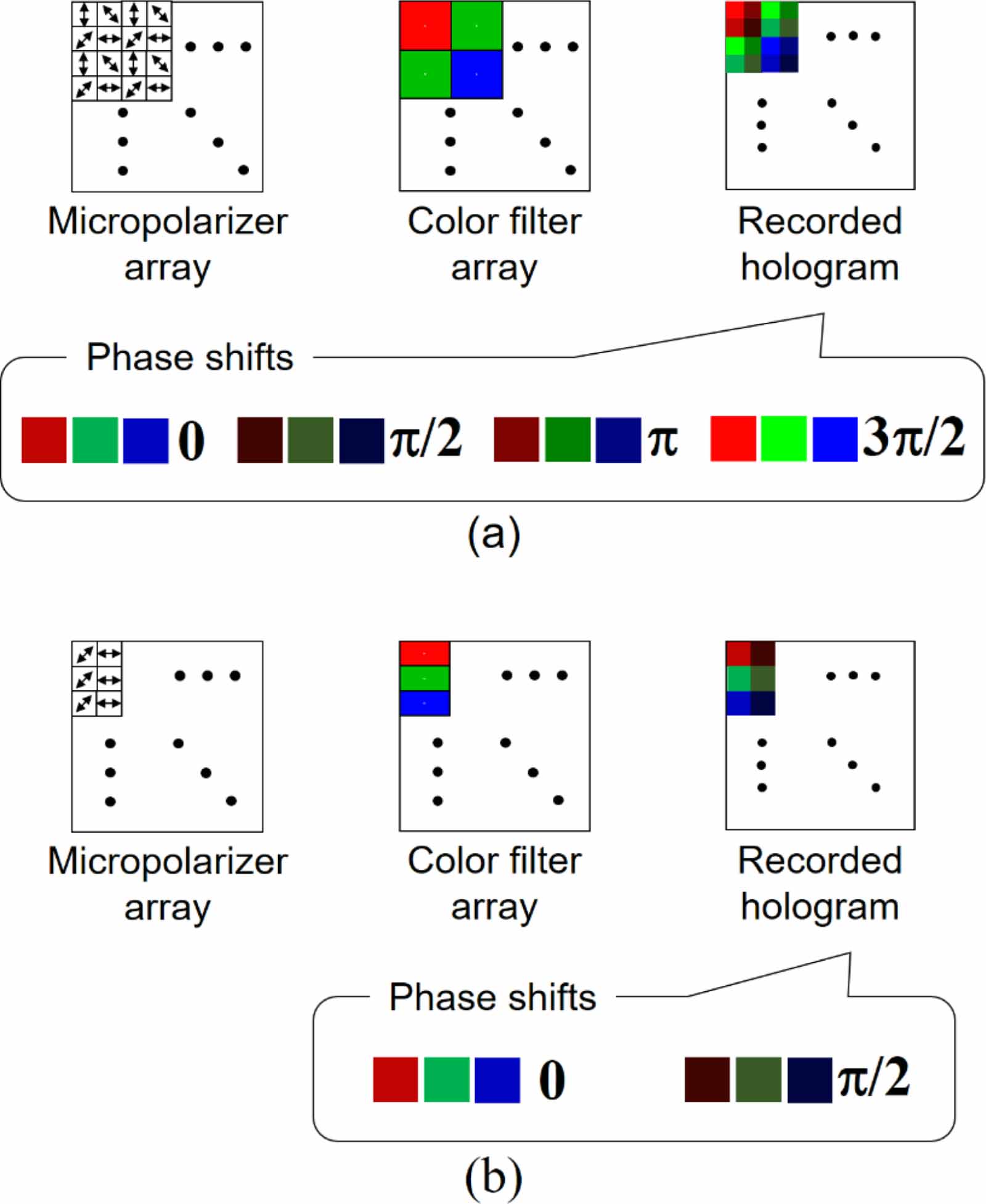
A polarization-imaging color image sensor records multiple phase-shifted holograms at red-, green-, and blue-color channels simultaneously. Both a micropolarizer array and a color filter array are attached to the image sensor to record both the polarization and wavelength information simultaneously with a single-shot exposure. We utilize polarization to record multiple phase-shifted holograms based on polarization phase-shifting interferometry. On the basis of space-division multiplexing [37–41], each pixel of an image sensor records one of the phase-shifted holograms at a certain color channel. When using a commercially available image sensor with Nx × Ny pixels and pixel pitch of px and py along the x- and y-axis directions, (x,y) = (px ,py ) is set to the center of the pixel placed in the upper left corner of the image sensor, and appropriate directions of x- and y-axes are right and downward, we obtain
where CFA(x,y) denotes a spectral transmission distribution of a color-filter array. We assume the transmittance distribution for red-, green-, and blue-wavelengths bands (λ1, λ2, λ3) as
When conducting phase-shifting interferometry with neighboring pixels, object waves at three wavelength bands on the image sensor plane U(x, y;λ1), U(x, y;λ2), and U(x, y;λ3) are derived from
or
and
After that, diffraction integrals for U(x,y;λ1), U(x,y;λ2), and U(x,y;λ3) are calculated to reconstruct 3D images at respective wavelength bands. Central wavelengths for respective wavelength bands are set to calculate diffraction integrals. Thus, from the recorded single incoherent hologram, a full-color 3D image of specimens is reconstructed after calculations for de-mosaicking, phase-shifting interferometry, and diffraction integrals. It is noted that polarization-sensitive optical elements are attached and z2 is set as zero, then equation (1) is simplified.
When using space-division multiplexing, there is a tradeoff between the recordable spatial information and other multiplexed information. In the proposed system, both polarization and color are multiplexed at the cost of the spatial information called the space-bandwidth product (SBWP). The number of transmission axes denotes the number of phase-shifted holograms, and four phase-shifted holograms are recorded simultaneously using a commercially available image sensor with a micropolarizer array. A commercially available polarization-imaging color image sensor has a micropolarizer array with four transmission axes and a Bayer color filter array, as shown in figure 3(a). Therefore, 12 holograms are recorded simultaneously, and the SBWPs at red- and blue-color channels are decreased to one-sixteenth of those without space-division multiplexing. To maximize the SBWPs in this single-shot incoherent holographic technique, the pixel arrangement shown in figure 3(b) is a possible solution. When adopting the arrangement in figure 3(b), two-step phase-shifting interferometry for each color channel is required. Therefore, one should estimate the zeroth-order diffraction waves at respective wavelengths in each color channel by a numerical method [42–44] and try some numerical filters to suppress or remove the undesired waves.
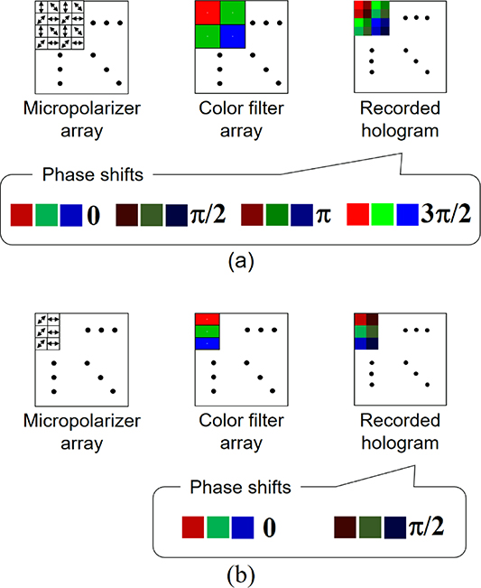
Figure 3. Pixel arrangements of image sensor with micropolarizer and color filter arrays. (a) Commercially available image sensor and (b) example specially designed to increase the recordable SBWPs.
Download figure:
Standard image High-resolution image3. Experiments
3.1. Single-shot incoherent color digital holographic microscopy imaging
We constructed the proposed system and conducted experiments to demonstrate the single-shot color 3D imaging of spatially and temporally incoherent light. Figure 4 shows the schematic and photograph of the constructed system. We used a commercially available inverted optical microscope (Olympus, IX-73) to obtain a magnified image of a specimen illuminated by a halogen lamp. The magnified image is focused after passing the output port of the microscope. We prepared a telecentric relay optics between the magnified image and the image sensor. We set two polarization-directed flat lenses on the optical Fourier-transform (FT) plane of the first lens in the relay optics. This means that we conducted point-spread-function (PSF) engineering for the phase distribution of a light wave. With these lenses set on the FT plane, the relationship between the spatial frequency of interference fringes and the spatial period of an object becomes spatially shift-invariant in the in-plane direction. The focal lengths of these lenses were ±45 mm and ±50 mm, respectively. A commercially available polarization-imaging color CMOS image sensor (Sony, IMX250MYR) was used to record the information of 12 holograms simultaneously. The magnification of the entire system was 37-fold. A USAF1951 test target was inserted into the optical microscope and an incoherent digital hologram was obtained. The de-mosaicking of the recorded hologram was numerically conducted. Phase-shifting interferometry was carried out and diffraction integrals were calculated at each wavelength to reconstruct a multicolor 3D image of the test target.

Figure 4. System constructed for experimental demonstrations. (a) Schematic and (b) photograph. A transmission-type self-interference incoherent inverted DHM system is constructed. Photograph is horizontally flipped.
Download figure:
Standard image High-resolution imageInitially, we set the magnified image of the test target on the plane near the image sensor plane and numerically investigated the refocusing ability. We set the frame rate at 10 frames per second (fps). Figure 5 shows the experimental results. The refocusing distances from the image sensor plane to the magnified images at red-, green-, and blue-color channels were −19 mm, −15 mm, and −5 mm, respectively. As seen in figure 5(d), a numerically focused color image was successfully reconstructed. Thus, refocusing and full-color imaging abilities were experimentally demonstrated with spatially and temporally incoherent white light. As another experiment, we set the magnified image of the target on the Fresnel domain by moving the target and obtained the hologram shown in figure 6(a). We set the frame rate at 22 fps to show a higher fps with a commercially available optical microscope. The exposure time was less than 50 ms and the number of pixels of a digital hologram was 2448 × 2048 pixels. By slightly tilting the image sensor toward the depth plane, we set different regions of the target at different depths. Figure 6 shows the experimental results. The recorded hologram had a mosaic pattern as shown in figure 6(b), and the focused color image was successfully reconstructed from the single hologram by image reconstruction procedures. Figures 6(c) and (d) indicate that by calculating diffraction integrals, we can reconstruct the focused images at the desired depths. Thus, the single-shot color 3D microscopy imaging of incoherent light at 22 fps was experimentally demonstrated. Figures 5 and 6 show that the full-color 3D imaging of 1 μm order structures is achieved from a single hologram recorded at a speed of 10-fps order using a commercially available optical microscope with a halogen lamp.

Figure 5. Experimental results with single hologram recorded at 10 fps. Images reconstructed from (a) red-, (b) green-, and (c) blue-color channels of recorded single hologram. (d) Color-synthesized image obtained from (a)–(c).
Download figure:
Standard image High-resolution image
Figure 6. Experimental results with single hologram recorded at 22 fps. (a) Recorded hologram and (b) magnified hologram in red-rectangle region of (a). Images focused on (c) group 7 and (d) group 8 of USAF1951 test target.
Download figure:
Standard image High-resolution imageNote that the frame rate is determined by the transfer capacity between the camera and the computer, and there is no problem in the video-rate recording in principle. On the other hand, the processing time is far from the real-time imaging. We investigated the processing time from the read-in of a recorded hologram to the image reconstruction of an object on a depth at a single-color channel. Table1 shows the implementation environment used for calculation time measurement. A single hologram with 2048 × 2048 pixels was used, and the image reconstruction procedure was repeated 1000 times. The average processing time and standard deviation for 1000 calculations were measured and were 1.16 s and 9.71 ms, respectively. Three times should be considered to obtain an RGB-color image of an object at a depth, and thus, it will require 3.5 s to obtain an image with 2048 × 2048 pixels. We investigated the processing time for (1) a read-in of a hologram and phase-shifting interferometry to extract an object wave from the record ed hologram, and (2) a diffraction integral to obtain an object image at a certain depth. The average processing times of (1) and (2) in 1000 calculations were 469 and 690 ms. It is important to accelerate the processing for real-time imaging, and the use of a graphics processing unit or a field-programmable gate array is a possible solution for accelerating the processing [3, 11].
Table 1. Implementation environment.
| OS | Windows 10 Professional 64 bit |
| CPU | Intel Core i7-8565U |
| Memory | 16 GB |
| Compiler | Visual Studio 2017 |
3.2. Image quality enhancement with a series of holograms
In the previous section, single-shot incoherent color digital holographic microscopy imaging was experimentally demonstrated. However, the lack of intensity to form a recorded hologram causes image quality degradation even for static objects, which becomes an important problem when increasing the frame rate. This is because there is a tradeoff between the temporal information capacity and the available light intensity when using an optical microscope. On the other hand, temporal information is important for observing biological and microscopic specimens in vivo, and thus we should avoid reducing the frame rate. In this section, we present an approach for flexibly using the recorded holograms after a series of holograms are recorded by the proposed system at a high frame rate. The presented approach is effective when living specimens are stable and avoids reducing the frame rate to record the motion of living specimens. In the presented approach, we summarize the holograms recorded when the specimen is stable and then increase the effective bit depth of the summarized hologram in comparison with that of a single recorded hologram. It is considered that this procedure is effective for low-light-intensity areas in stable specimens.
We set the magnified image of the test target on the plane near the image sensor plane to show the effectiveness of the presented approach. We set the frame rate at 20 fps and summarized 20 holograms. Figure 7 shows the experimental results. The difference in refocusing distance between figures 7(a) and (c) was 5 mm in the image plane. As seen in figure 7, focused images with white color were successfully reconstructed, and the image quality was much improved in comparison with the results shown in figure 5. Thus, the full-color 3D imaging ability with improved image quality was experimentally demonstrated with spatially and temporally incoherent white light. As another experiment, we obtained 22 digital Fresnel holograms with a recording speed of 22 fps. Figure 8 shows the experimental results. From the synthesized hologram shown in figure 8(a), full-color images focused at arbitrary depths were reconstructed as shown in figures 8(b) and (c). The difference in refocusing distance between figures 8(b) and (c) was 29 mm in the image plane, which corresponded to 21.2 μm in the object plane. In the same manner as shown in figure 7, the image quality in digital Fresnel holography was much improved compared with that shown in figure 6. Note that figure 6(a) is one of the recorded holograms in figure 8(a). Thus, the full-color 3D microscopy imaging of incoherent light was experimentally demonstrated. By using the presented approach, it is expected that we can flexibly obtain a 3D motion picture with high temporal resolution for moving 3D specimens and that with low temporal resolution but with high image quality for static 3D specimens.

Figure 7. Experimental results with synthesized hologram generated from 20 holograms. (a) Color-synthesized and reconstructed image and (b) magnified image of part of (a). Focused areas are borders of groups 7, 8, and 9. (c) Reconstructed full-color image and (d) magnified image of part of (c). Focused areas are stripes of groups 7, 8, and 9.
Download figure:
Standard image High-resolution image
Figure 8. Experimental results with Fresnel hologram synthesized from 22 holograms. (a) Synthesized hologram. (b) Reconstructed and color-synthesized image. The magnified image of two thin strings is numerically focused in (b). (c) Full-color image of USAF1951 test target reconstructed with numerical focusing. Green rectangles in (a)–(c) indicate the area where the magnified image of the two strings is focused and defocused.
Download figure:
Standard image High-resolution image3.3. Investigation for quantitative 3D sensing ability
In this section, we conducted additional experiments with the setup shown in figure 4 to demonstrate quantitative 3D sensing ability. DHM is one of the quantitative 3D sensing techniques and axial information is retrieved from a single hologram. The proposed DHM adopts a self-interference incoherent DH system and 3D information is retrieved by the calculations of numerical refocusing for the extracted complex amplitude distribution of an object on the image sensor plane. We investigated the quantitative 3D sensing ability by the following procedures. We set the magnified image of a USAF1951 test target on a plane and obtained a single hologram. Then, the 10 μm movement of the specimen along the axial direction in the object plane and the recording of a digital hologram were repeated. Reconstructed images were obtained from the green channel of the holograms. From the series of the images reconstructed from the recorded holograms, axial positions of the focused images were obtained. It is noted that, in self-interference DH, there is no proportional relationship between the axial positions of the specimen and the reconstructed image [45]. Figure 9 illustrates the three cases where the two object waves generate interference fringes on the image sensor plane. In the case of figure 9(a), divergent and convergent object waves generate a fine interference fringe image and super-resolution imaging in the in-plane direction is demonstrated by FINCH systems [13, 25, 27]. In figure 9(b), one of the object images is imaged onto the image sensor plane. In figure 9(c), the two divergent waves generate an interference fringe image. It has been described in [45] that the magnification in the depth direction is different between the cases of figures 9(a) and (c) and is particularly decreased when the axial position Z of the magnified image of the specimen is less than zero, which corresponds to the case of figure 9(a). In the system shown in figure 4, f1 and f2 were 180 and 167 mm. Figure 10 shows experimental results. We plotted the axial positions of the reconstructed images and theoretical values. Theoretical values were obtained from the magnification of the constructed optical system, the distances between the image sensor plane and the axial positions of the focused two object images Z1, Z2 on the image plane, and the axial position of the image reconstructed with numerical reconstruction Zc in [45]. Figure 10 shows good agreement between the experimental and theoretical values. Quantitative values of the axial positions can be obtained by using the theoretical values. The theoretical values are obtained from the magnification of the optical system and axial positions of the two object images. The axial positions of the two object images are determined by the optical system and the focal lengths of the polarization-directed flat lenses. Therefore, quantitative 3D image sensing can be conducted by self-interference incoherent DHM with careful design of the optical system. As another way, it is also valid to make a look-up table between the axial positions of the reconstructed image and an object set for the calibration of the system, which is for the detection of the axial information quantitatively. Thus, quantitative 3D sensing ability was experimentally and successfully performed.

Figure 9. Three cases where the two object waves generate interference fringes on the image sensor plane in self-interference incoherent DHM. (a) Two object waves are convergent and divergent waves respectively, and the diameter of the divergent wave is not less than that of the convergent wave. (b) One of the object waves is imaged onto the image sensor plane and the other is divergent wave. (c) Both the two waves are divergent ones.
Download figure:
Standard image High-resolution image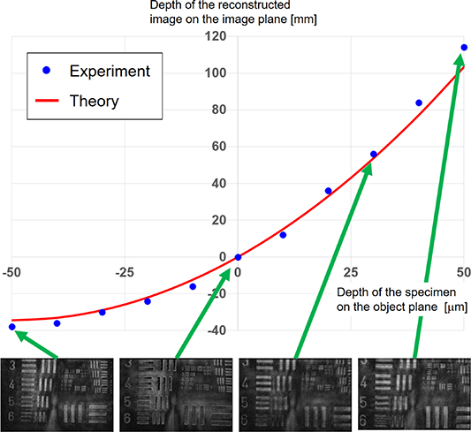
Figure 10. Experimental results for quantitative 3D sensing. Reconstructed images at green channel on the respective axial positions were also shown. In this graph, we set Z as minus, zero, and plus for the cases of figures 9(a)–(c), respectively.
Download figure:
Standard image High-resolution image
4. Conclusion
We have proposed a digital holographic microscope for the single-shot color 3D image sensing of specimens illuminated by spatially and temporally incoherent white light. Static polarization-sensitive optical elements were exploited to generate two object waves with different curvature radii. The microscope does not require any SLMs to construct a FINCH system. The color holographic 3D motion picture recording of spatially and temporally incoherent white light at 22 fps was experimentally performed with the proposed microscope. In [33], the frame rate was 1.67 fps with a magnification of 20-fold, and thus the proposed microscope achieved a 45.1-fold light-use efficiency. This value is calculated from the square of the magnification and the frame rate. The series of recorded holograms was successfully utilized for image quality enhancement to achieve both dynamic range extension and white noise suppression. It can be considered that an applicable color image sensor not only has a Bayer color filter array but also an RGB-stacked color image sensor [46] and three image sensors with a prism or wavelength filters [47]. Computational coherent superposition is also considered as another way of recording wavelength information [48–50]. The proposed system will contribute to observations of dynamically changing color 3D phenomena and multiple specimens moving in a 3D area simultaneously.
Funding and Acknowledgments
Japan Science and Technology Agency, Precursory Research for Embryonic Science and Technology (PRESTO) (JPMJPR16P8); Japan Society for the Promotion of Science (JSPS) (18H01456).