

Abstract
Biomechanists and biologists alike have yet to fully understand the complex morphology and function of shark denticles, morphologically intricate tooth-like structures embedded into the skin of sharks. Denticles vary in many ways (such as size and shape) depending on shark species, and studies on denticle hydrodynamics have suggested that they may aid in drag reduction as well as increase both lift and thrust. Although previous studies have analyzed the effect of different denticle patterns on hydrodynamic performance, no previous work has focused on the effects of denticle size. Here, we report on the hydrodynamic properties of 3D printed shark skin foils with rigid denticles embedded into a flexible substrate. The patterning of these denticles was based on previously reported designs exhibiting the greatest hydrodynamic performance (which also most closely mimics real shark skin). The size of the denticles and the speed of the flow were varied, and the foils were evaluated under both static and dynamic conditions. Static tests showed drag reduction compared to a smooth control foil (without denticles) for the smallest denticle size, while medium and large denticles exhibited increased drag. Under dynamic testing conditions, the smallest denticles increased the self-propelled swimming speed, while the largest denticles reduced swimming performance. At higher speeds, the smallest denticles were also able to reduce power consumption compared to the control, demonstrating that their hydrodynamic effect depends on both denticle size and swimming speed. Our results thus provide new insights into the role of denticle size in shark swimming hydrodynamics across a range of locomotory modes, while simultaneously providing new design guidelines for the production of high performance low drag surface coatings for aquatic and aerospace applications.
Export citation and abstract BibTeX RIS
1. Introduction
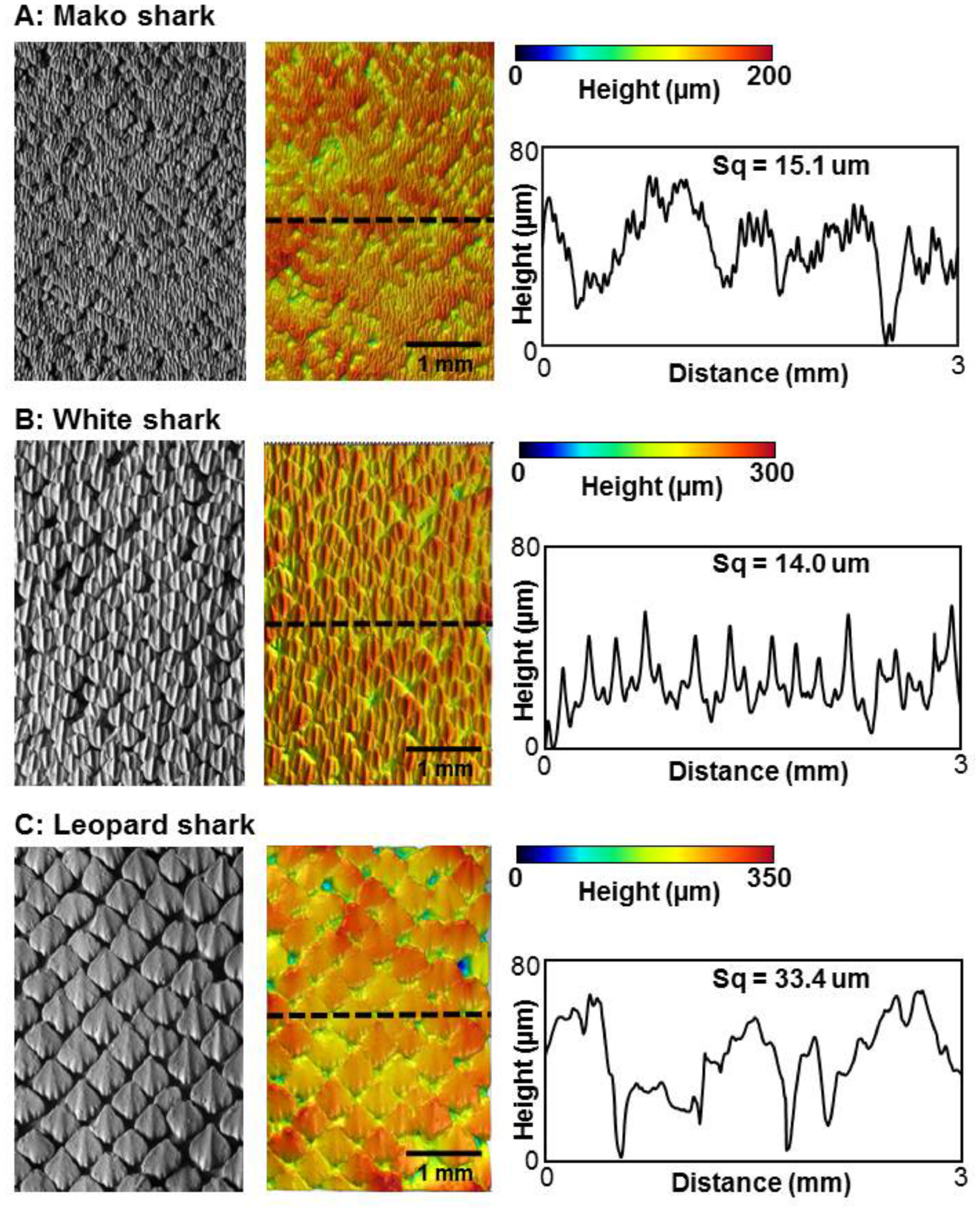
Sharks are an extremely diverse group of vertebrates with nearly 450 species that inhabit a wide variety of habitats from the open ocean to near-shore and benthic environments (Hamlett 1999, Castro 2011, Carrier et al 2012, Klimley 2013). One fascinating aspect of shark biology that has been extensively studied is the function of their skin, which is covered with many thousands of tooth-like denticles or scales, and has been postulated to play an important role in locomotion (e.g. Bechert et al (1985), Reif (1985), Motta et al (2012), Wen et al (2014), Ankhelyi et al (2018) and Domel et al (2018)). Each denticle is covered in an enamel-like coating and often exhibits multiple surface ridges, which are generally aligned along the direction of water flow over the body and fins (figure 1). There is considerable diversity in the patterning of skin denticles, in the alignment of denticle ridges across the surface, and variation in the spacing and hence overlap among adjacent denticles (Reif 1985, Castro 2011). Denticles can also vary considerably in shape, both along the body of an individual, and among different species. Denticles can be round and peg-like, diamond-shaped with ridges and pointed posterior margins, or they can lack surface ornamentation and have a smooth and rounded posterior edge (Ankhelyi et al 2018).
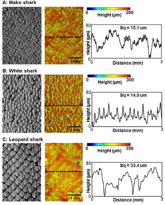
Figure 1. Variations in denticle surface patterning in three species of sharks. The denticle surface of each species was imaged in three dimensions using gel-based surface profilometry (see methods). Data are shown for a mako shark (Isurus oxyrinchus), white shark (Carcharodon carcharias), and leopard shark (Triakis semifasciata). For each species, a surface image is shown (left), the same image with height indicated in color (middle), and a height profile at the location of the dashed line (right). Water flow over the skin surface is from bottom to top. Measurements of surface roughness (Sq, see methods) are given above each profile.
Download figure:
Standard image High-resolution imageA primary axis of variation in shark denticles lies in their size, and individual denticles in different species can vary from larger than one millimeter to as small as 120 µm (Castro 2011, Dillon et al 2017, Ankhelyi et al 2018). Changes in denticle size affect the overall surface patterning and roughness characteristics as shown in figure 1, where variation in denticle patterning is compared among three species of sharks. Species such as the leopard shark Triakis semifasciata, have individual denticles greater than 0.5 mm in length, while shortfin mako sharks (Isurus oxyrinchus) have among the smallest denticle sizes (200 µm in length). White sharks (Carcharodon carcharias, figure 1) possess intermediate sized denticles as do many other open ocean species. Denticle size also affects overall surface roughness and the frequency characteristics of height variation over the surface, with the larger denticles of leopard sharks exhibiting twice the skin surface roughness of mako sharks (figure 1).
In recent years, a number of studies have aimed to understand the functional significance of shark denticles by computationally simulating steady flow over denticles, although such studies have arrived at contradictory conclusions as to the possible drag reduction effect of denticle shapes (Díez et al 2015, Boomsma and Sotiropoulos 2016). Denticles in at least a few species also appear to be relatively loosely anchored in the skin, and it has been suggested that these passively mobile denticles may change boundary layer characteristics of water flow over the body (Lang et al 2008, 2014). Experimental studies of highly simplified denticle models (such as simple linear ridges) have demonstrated drag reduction under static test conditions with constant flow (Bechert et al 1985, Dean and Bhushan 2010, Yuehao et al 2012), but the hydrodynamic conditions of these tests may not reflect the dynamic and time-varying flows experienced by the skin of sharks as they swim.
Another approach to understanding the functional significance of denticles has been to use either real pieces of shark skin (Oeffner and Lauder 2012) or 3D printed biomimetic shark skin models (Wen et al 2014, 2015, Lauder et al 2016) attached to a robotic flapping controller which moves the skin and models in a biologically realistic manner (with appropriate frequencies and surface curvature). Testing shark skin in this way and under conditions of self-propulsion in the laboratory allows denticle-covered surfaces to experience both drag and lift forces naturally during oscillatory motion, and recent work has demonstrated that these surfaces can increase lift when added to airfoil surfaces (Domel et al 2018) and increase thrust generation in a flapping propulsive system. These experimental tests of shark skin under conditions of propulsion also have the benefit of allowing calculation of the cost of transport (COT) and power consumption by different arrangements of denticles on the skin surface during swimming, and of direct comparisons to a manufactured smooth control surface of the same mass (Wen et al 2015).
However, to date, these experimental studies have not considered the effects of denticle size alone. To address this question, we first 3D printed biomimetic model membranes of shark skin at different size scales along with corresponding smooth controls of the same mass. Second, we conducted static testing at different imposed flow speeds to determine how denticle size affects drag forces using 3D printed denticle membranes as compared to smooth control surfaces at a variety of Reynolds numbers. Third, we conducted a series of dynamic tests at two Reynolds numbers in which 3D printed shark skin membranes with differently sized denticles swam under conditions of self-propulsion to investigate the relationship between denticle size and power consumption during propulsion. We used these data to test the hypothesis that smaller denticles reduce power consumption of propulsion compared to surfaces covered with larger denticles.
2. Materials and methods
2.1. Creating the shark denticle model
Using micro-computed tomography (micro-CT) data (XradiaVersaXRM-500, Zeiss, Oberkochen, Germany) obtained from denticles from the short fin mako (Isurus oxyrinchus), and as described previously by Wen et al (2014, 2015) and Lauder et al (2016), we created the representative shark denticle model shown in figure 2 using Mimics 3D (Materialise Inc., Leuven, Belgium) to segment the raw data and SolidWorks for generation of the final parametric model (SolidWorks Corp., Waltham, MA, USA). In figure 2, lc is the chordwise length of the denticle, ls is the spanwise length, and lr is length of the side ridges (the denticle is symmetric about its middle ridge—see figure 2(A)). Moreover, h1 is the height of the middle ridge from where it anchors into the skin surface, and h2 is the height of the side ridge (see figures 2(B) and (C)). We kept lc/ls = 1.37, lc/lr = 1.25, h1/h2 = 1.2, and lc/h1 = 1.67 constant for all representative denticles. An lc of 2.1 mm was used for the membrane with the smallest denticles, lc = 3.15 mm for the medium denticles, and lc = 4.2 mm for the largest denticles. This model denticle was then arrayed in a staggered-overlapped pattern on the membrane surface, a pattern which was found to be most hydrodynamically beneficial by Wen et al (2015). This staggered-overlapped pattern is shown in figure 2(D), where Ss is the spacing between denticles in the streamwise direction, and Sl is the spacing between denticles in the lateral direction (Ss/Sl = 1 was kept constant throughout this study).
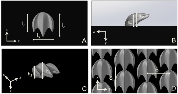
Figure 2. (A) Top, (B) side, and (C) isometric view of the representative shark denticle model used in this study. (D) The shark denticle model was then arrayed in a staggered-overlapped pattern. Dimensions used to design the denticle foils included lc, lr, ls, h1, h2, Si and Ss. lc is the chordwise length of the denticle, ls is the spanwise length, and lr is length of the side ridges (the denticle is symmetric about its middle ridge). h1 is the height of the middle ridge from where it anchors into a surface, and h2 is the height of the side ridge. We kept lc/ls = 1.37, lc/lr = 1.25, h1/h2 = 1.2, lc/h1 = 1.67, and Ss/Sl = 1 constant for all biomimetic denticles and surfaces in this study.
Download figure:
Standard image High-resolution image2.2. Manufacturing biomimetic shark skin surfaces
In this study, we aimed to understand how denticle size affected the hydrodynamics of shark skin surfaces. Since these surfaces would be tested not only statically, but also dynamically using a robotic flapping device, the surfaces had to be flexible. To meet this need, we employed multi-material 3D printing using a Objet Connex500 3D Printer (Stratasys Ltd, Eden Prairie, MN, USA) for the production of three composite shark skin surfaces that consisted of an array of rigid denticles embedded in a flexible membrane as a single integrated model (figure 3). The membrane surface itself was printed out of a black flexible rubber-like material (FLX980; with Young's modulus E ~1 MPa), while the denticles were printed out of a clear rigid thermoplastic-like material (RGD810; with Young's modulus E ~1 GPa). Three different flexible biomimetic shark skin surfaces were created, each with a different size of denticles arrayed in the same staggered-overlapped pattern shown in figure 2(D). All three membranes had the same chord and span length (157 mm and 68 mm, respectively), and thus had the same Reynolds number based on the foil cord length, ReC, at a given flow speed (as described by Wen et al (2015)). For all subsequent descriptions of these models, we refer to the membrane with the smallest denticles as '1×', the membrane with medium denticles as '1.5×' and the largest as '2×'. The thickness of the flexible 1× membrane was set to 1.44 mm, and this value was scaled up with each additional membrane proportional to the size of the denticles. For each of the three different biomimetic shark skin membranes with differently sized denticles, two membranes were 3D printed. Each of the two membranes for a given denticle size was adhered to each side of a yellow plastic shim-stock 'backbone' with thickness of 0.508 mm and flexural stiffness of 9.8 × 10⁻⁴ N m−2, resulting in a composite foil with denticles on both sides. Thus, the final foil for each of the three types of shark skin surfaces consisted of a shark skin membrane of a given denticle size on each side of this yellow plastic backbone (figure 3). The yellow plastic support was laser cut with an extra 1 cm in chord length (with three holes at the end—see figure 3) so that the foil could be attached to the robotic flapping device described below.
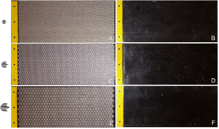
Figure 3. Images of the six foils tested in this study: biomimetic shark skin foils on the left and the corresponding smooth control foils of the same mass on the right. Denticle images scaled relative to each other are shown to the left of the foils. The black material pictured above is flexible so that all of the foils move in a fish-like motion when dynamically tested. The size of rigid denticles embedded in the biomimetic shark skin foils was varied, and the mass of the control adjusted accordingly. (A) shows the 1× denticle foil (lc = 2.1 mm) while (B) shows its corresponding smooth control foil, (C) shows the 1.5× denticle foil (lc = 3.15 mm) while (D) shows its corresponding smooth control foil, (E) shows the 2× denticle foil (lc = 4.2 mm) while (F) shows its corresponding smooth control foil. The yellow tab to the left of each foil was 10 mm in width and was used to attach the foils to the robotic flapping device. The foil chord and span length were 157 mm and 68 mm, respectively.
Download figure:
Standard image High-resolution imageEach of the three denticle foils had its own denticle-free control foil of identical total mass (a 3D printed plain, smooth black flexible membrane with the same mass, chord and span length as the denticle-containing foils). To accomplish this, the control thickness was adjusted relative to the denticle foils to match the mass of the respective denticle foil (ensuring that inertial effects would not play a role in the dynamic testing when comparing each denticle foil to their control). The small increase in thickness did not observably affect the stiffness of the membranes since the flexural stiffness of the entire assembled foil (figure 3) was dominated by the stiffness of the central plastic backbone (also see Wen et al (2015) for further discussion of this point). Using the above mentioned naming schemes, we will refer to these control foils as the '1× control', '1.5× control', and '2× control'. In general, our approach to designing and manufacturing the flexible foils was similar to that used in our previous work investigating shark skin denticle performance (see Oeffner and Lauder (2012), Wen et al (2014, 2015) and Lauder et al (2016)). The parameters for each of the 6 foils tested in this study (as shown in figure 3) can be found in table 1 which provides key characteristics of each of the tested denticle foils and their corresponding controls.
Table 1. Parameters for each of the 6 foils tested in this study: 3 biomimetic shark skin foils and their 3 corresponding smooth controls (values include both sides of the foil). Ss is the spanwise distance between denticles and Sl is the distance along the chord between denticles.
| Sharkskin morphology | 1× control | 1× denticles | 1.5× control | 1.5× denticles | 2× control | 2× denticles |
|---|---|---|---|---|---|---|
| Ss (mm) | — | 2.05 | — | 3.075 | — | 4.10 |
| Sl (mm) | — | 2.05 | — | 3.075 | — | 4.10 |
| # of denticles | 0 | 4950 | 0 | 2200 | 0 | 1184 |
| Denticle surface area (mm2) | 0 | 42 006 | 0 | 41 998 | 0 | 40 189 |
| Membrane surface area (mm2) | 21 352 | 17 628 | 21 352 | 17 626 | 21 352 | 17 788 |
| Total surface area (mm2) | 21 352 | 59 634 | 21 352 | 59 624 | 21 352 | 57 977 |
2.3. Imaging biological shark skin and biomimetic shark skin surfaces
Imaging the skin of three species of sharks (figure 1) and the biomimetic denticle and control membrane surfaces (figure 4) was performed using gel-based surface profilometry (GelSight Incorporated, Waltham, Mass, USA) as described previously by Wainwright and Lauder (2016) and Wainwright et al (2017, 2018). Each of the resulting 3D data sets had dimensions of 4.5 by 3 cm in x and y and contained 18 million x, y, z coordinates providing a detailed representation of surface elements and their patterning. Image resolution was 5208 by 3476 pixels, with additional z (height) data for each pixel. Surface profile data were analyzed using MountainsMap software (v. 7 Digital Surf, Besançon, France) to generate image maps of surface height (figures 1 and 4) and to quantify the surface roughness parameter Sq. Sq was calculated as the square-root of the sum of the squared distances of each point from the mean height (units are in µm).
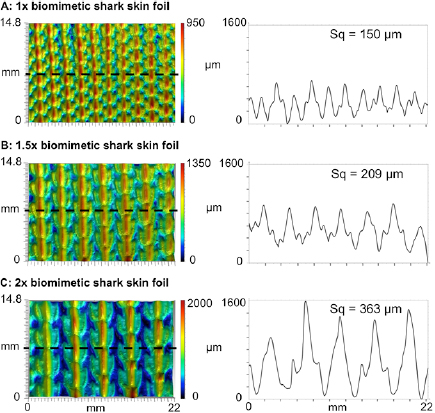
Figure 4. Surface patterning in the three biomimetic foils tested to illustrate height variation and denticle spacing among the different flexible biomimetic membranes. The upper panels show the 1× denticle size (A), the middle panels the 1.5× denticle size (B), and the bottom panels the 2× size (C). The surface of each membrane was imaged in three dimensions using gel-based surface profilometry (see methods). For each foil, a surface image is shown with height indicated in color (left), and a height profile at the location of the dashed line (right). Measurements of surface roughness (Sq, see methods) are given above each profile.
Download figure:
Standard image High-resolution imageDue to resolution limitations of modern multi-material 3D printers, we were not able to print denticles at the smallest sizes present on living shark species (figure 1). Attempts to print at denticle sizes with lc less than 2 mm (figure 2) resulted in an unacceptable distortion of smaller surface features such as the ridges, valleys, and posteriorly pointed tips on the denticle surface (also see the discussion on printing denticles in Wen et al (2015)). As a result, the smallest size denticles tested here were 2–5 times the denticle size common in many sharks, and more than 10 times larger than for fast open ocean pelagic sharks such as the mako (figure 1; Ankhelyi et al 2018). The ability to print arrays of thousands of rigid denticles on a flexible substrate at a denticle size of 0.5 mm or smaller with accurate surface features on the order of 25 microns in size (or less) awaits new advances in 3D printing technology.
2.4. Static testing
Each of the 6 foils were tested statically (held still, with no motion of the leading edge) in a recirculating water flow tank with working dimensions 26 cm × 26 cm × 80 cm. The testing apparatus was the same as that used in previous studies on foil propulsion and shark denticle hydrodynamics (Lauder et al 2012, Shelton et al 2014, Wen et al 2014, 2015). Each foil was attached to a mounting rod that held the foil under water with the foil placed in the center of the tank and oriented parallel to the incident flow. Using a six-axis load cell (Nano-17, ATI Industrial Automation Inc., Apex, NC, USA), drag forces were measured by finding the average force on the foil parallel to the direction of flow over a period of 10 s. Drag forces were recorded at speeds ranging from 0.1 m s−1 to 0.5 m s−1 in increments of 0.05 m s−1. With a membrane chord length of 157 mm for each foil, this gave a ReC (Reynolds number with chord as characteristic length) range of approximately 1.5 × 10⁴–8 × 10⁴. Each foil was tested at each flow speed a total of 6 times, and the standard error for the drag force measurements at each speed was determined.
Drag coefficients for static foil tests were calculated using the following equation:

where A is the foil area, ρ ≈ 1000 kg m−3 is the density of water, U is the flow speed, and FD is the drag force experimentally measured for each foil at each given flow speed.
2.5. Dynamic testing
For dynamic testing, where the foils were moved and propelled or swam against oncoming flow, the holding rod to which the foils were attached was connected to a rotary motor (Pittman, GM8724S009). In order to attain a fish-like swimming motion for the foils, the rotary motor generated a pitch motion of the rod in a sinusoidal pattern to create undulatory waves in the foil surface (also see Saadat et al (2017)). From the six-axis load cell (ATI Nano-17: ATI Industrial Automation, Apex, NC, USA) attached to the holding rod, forces and torques were measured during propulsion. Using this experimental arrangement, two forms of dynamic testing were carried out: (i) measurement of self-propelled swimming speed (SPS) for a given set of foil motion parameters (referred to as a motion program), and (ii) determining power coefficient curves over a range of motions under conditions of self-propulsion following procedures outlined in Saadat et al (2017).
For the first set of dynamic tests—finding SPSs for a given locomotion—a range of leading edge pitch motions (θ) and frequencies (f) were chosen for each of the foils, to generate a fish-like swimming motion. Previous research by Oeffner and Lauder (2012) had shown that this range of leading edge pitches and frequencies generate foil curvatures that approximate those of freely-swimming sharks. As the front of the foil is pitched by the holding rod, a traveling undulatory wave is sent down the body of the foil, and this fish-like flapping motion allows the foil to generate thrust (Saadat et al 2017). Self-propelled speed, where average thrust is zero over a flapping cycle (Lauder et al 2011), was determined using a custom LabView program that altered the imposed free-stream flow and measured average thrust at each speed. This procedure to determine self-propelled speed was repeated five times for each motion and standard error for each measurement was calculated. Note that for each of the three different denticle foils, three motion programs to explore self-propelled speeds were chosen that corresponded to each of the foils' most efficient swimming-like motion (these motion programs were identified based on the results obtained from additional dynamic testing discussed in the following sections). COT was also reported for all of the swimming motions as the locomotor power (which was computed as the torque generated by the foil, Tz, times the angular velocity of the pitching motion, vp) divided by the self-propelled swimming speed, SPS, for that motion.


For the second set of dynamic testing experiments, obtaining power coefficient curves over a range of motions when the foil is self-propelling (see Saadat et al (2017)), testing was conducted at two chord-based Reynolds numbers: ReC = 3 × 10⁴ and 5.3 × 10⁴. The frequency-amplitude space of the motion of the foil (body waves created by the pitching of the foil) was explored at each Reynolds number in order to discover which frequency and pitching amplitude parameters generated a desired self-propelled speed. Essentially, the imposed free-stream flow was set to the value of that of the desired self-propelled speed, and as the foil dynamically moved at a given pitch amplitude, a series of pitch frequencies were input until the net force parallel to the flow on the foil was zero (meaning that it was then swimming at the desired self-propelled speed). Then, for the frequency at which the foil was self-propelling at that given pitch input, the side-to-side amplitude of the trailing edge was measured (using high speed videos taken at 2000 Hz and at a resolution of 1024 pixels by 1024 pixels with a Photron mini-UX100 high-speed video camera). Measured amplitudes were then divided by the length of the foil to obtain non-dimensional amplitude, A* = A/L. Power input to the foil was measured as described above to calculate a power coefficient (Cp) for each experimental test. These measurements were performed for a series of different imposed leading edge pitch amplitudes to construct a Cp versus A* curve (as in figure 9). Cp is calculated as follows:

where P is the measured power,  is the density of water (1000 kg m−3), U is the imposed free-stream flow speed, and S is the undeformed planform area of the foil. This curve describes the amount of power required for the foil to self-propel at a given trailing edge amplitude. Finally, following the procedures outlined in Saadat et al (2017), we plotted non-dimensionalized trailing edge amplitude A* against nondimensionalized frequency f *(=f L/U) to capture and better understand the dynamics of the undulatory propulsion of the various denticle foils.
3. Results
3.1. Static testing
Experimental results of static drag testing are shown in figure 5. In this plot, the Ds/Dm ratio evaluates whether the denticle foil surfaces are reducing or increasing drag compared to the smooth control surfaces. Ds is the drag force experienced by a denticle foil, while Dm is the drag force experienced by the denticle foils' corresponding smooth control surface. Thus, Ds/Dm = 1 (which is shown as the dashed line in figure 5) corresponds to no difference in drag force between the denticle foil and its corresponding smooth control, whereas Ds/Dm < 1 (below the dashed line in figure 5) demonstrates drag reduction for the denticle foil.
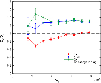
Figure 5. Static testing of drag forces experienced by each of the three tested biomimetic foils relative to their corresponding control plotted versus Reynolds number (ReC—the Reynolds number based on the foil chord). Ds represents the drag experienced by a given shark skin foil at a given ReC, whereas Dm represents the drag experienced by the shark skin's corresponding smooth control foil. Thus, Ds/Dm is a measure of how much the shark denticles are either increasing or decreasing drag compared to the corresponding control surfaces under uniform flow conditions. The dashed line represents Ds/Dm = 1, which is the case in which the shark skin foil and its corresponding control are producing the same amount of drag. Error bars are standard errors, N = 6 trials.
Download figure:
Standard image High-resolution imageOnly the 1× shark skin foil exhibited drag reduction compared to the smooth control (figure 5), and it did so at seven of the nine Reynolds numbers tested. At lower speeds, drag reduction of the 1 × shark denticle foil was most pronounced; however, at higher speeds the drag experienced by the 1× foil became greater than that of the control (Ds/Dm = 0.89, 0.69, 0.82, 0.86, 0.90, 0.97, 0.97, 1.01, 1.03 at ReC = 1.57 × 10⁴, 2.36 × 10⁴, 3.14 × 10⁴, 3.93 × 10⁴, 4.71 × 10⁴, 5.50 × 10⁴, 6.28 × 10⁴, 7.07 × 10⁴, 7.85 × 10⁴, for the 1× denticle foil respectively). For the larger denticles, drag reduction compared to their respective controls was never seen at any flow speed: denticle foils of the 1.5 × and 2 × sizes exhibited higher drag relative to the smooth control at all tested speeds (figure 5). (Ds/Dm = 1.19, 1.12, 1.27, 1.27, 1.30, 1.31, 1.33, 1.30 and Ds/Dm = 1.18, 1.49, 1.40, 1.30, 1.28, 1.29, 1.34, 1.31, 1.31 at ReC = 1.57 × 10⁴, 2.36 × 10⁴, 3.14 × 10⁴, 3.93 × 10⁴, 4.71 × 10⁴, 5.50 × 10⁴, 6.28 × 10⁴, 7.07 × 10⁴, 7.85 × 10⁴, for the 1.5 × and 2 × denticle foils respectively).
Drag coefficients (CD) for the various foils swimming at different flow speeds, and hence Reynolds numbers, are reported in figure 6. All denticle foils exhibited lower drag coefficients compared to the corresponding control foils when the total wetted surface area was used in the CD calculation (figure 6(A)), since the denticle foils have a much larger wetted surface area due to their complex surface undulations and overlapping geometries (table 1). In figure 6(B), when using the planform area for all tested foils to calculate drag coefficients, shark skin foils exhibited drag coefficients that were usually higher than their respective controls, except for speeds at which the 1× denticle foil showed reduced drag compared to its control.
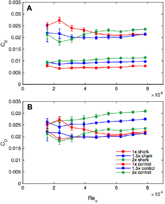
Figure 6. Experimental drag coefficient (CD) data from static testing as a function of the Reynolds number based on the foil chord (ReC) for each of the six foils (three shark skin foils of different size denticles as well as their corresponding controls). In (A), drag coefficients are calculated using the total wetted surface area (see table 1), whereas in (B), drag coefficients are calculated using the planform area of the surface. Error bars are standard errors, N = 6 trials.
Download figure:
Standard image High-resolution image3.2. Dynamic testing
Results for self-propelled speed measurements and the COT calculations for the 1× denticle foil and its corresponding control are shown in table 2 (the location that these motions lie on the Cp versus A* plane is labeled 1–9 in both figure 7 and the various tables of the results section), with corresponding results for the 1.5× and 2× foils in tables 3 and 4, respectively. For all three motion programs, the 1× denticle foil had a higher SPS than its respective control (table 2) despite having a wetted surface area more than twice that of the smooth control (table 1). For the 1.5× foil tests, the self-propelled speed was higher for this denticle foil at the highest frequency (2.5 Hz), similar for the middle frequency (2 Hz), and slower for the lowest tested frequency (1.25 Hz) (table 3). The largest denticle foil size (2×) showed slower SPS for all three tested frequencies (table 4).
Table 2. Self-propelled speed and COT for each of the various swimming motions tested for the 1× biomimetic shark skin foil and its corresponding control. See figure 7 to locate where these pitch/frequency motions lie on the power coefficient-amplitude plane.
| Point from figure 7 | Pitch [deg.] | Frequency [Hz] | SPS of control (m s−1) | SPS of shark skin foil (m s−1) | COT of control (J m−1) | COT of shark skin foil (J m−1) |
|---|---|---|---|---|---|---|
| 1 | 15 | 2 | 0.184 ± 0.0104 | 0.199 ± 0.0035 | 0.082 ± 0.0046 | 0.086 ± 0.0016 |
| 2 | 20 | 1 | 0.157 ± 0.0019 | 0.195 ± 0.0020 | 0.072 ± 0.0009 | 0.096 ± 0.0023 |
| 3 | 25 | 1.5 | 0.202 ± 0.0025 | 0.235 ± 0.0048 | 0.138 ± 0.0123 | 0.163 ± 0.0034 |
Table 3. Self-propelled speed and COT for each of the various swimming motions tested for the 1.5× biomimetic shark skin foil and its corresponding control. See figure 7 to locate where these pitch/frequency motions lie on the power coefficient-amplitude plane.
| Point from figure 7 | Pitch [deg.] | Frequency [Hz] | SPS of control (m s−1) | SPS of shark skin foil (m s−1) | COT of control (J m−1) | COT of shark skin foil (J m−1) |
|---|---|---|---|---|---|---|
| 4 | 15 | 2.5 | 0.169 ± 0.0055 | 0.199 ± 0.0119 | 0.172 ± 0.0056 | 0.145 ± 0.0087 |
| 5 | 20 | 2 | 0.200 ± 0.0064 | 0.190 ± 0.0109 | 0.155 ± 0.0049 | 0.174 ± 0.0010 |
| 6 | 25 | 1.25 | 0.188 ± 0.0054 | 0.169 ± 0.0030 | 0.132 ± 0.0038 | 0.190 ± 0.0034 |
Table 4. Self-propelled speed and COT for each of the various swimming motions tested for the 2× biomimetic shark skin foil and its corresponding control. See figure 7 to locate where these pitch/frequency motions lie on the power coefficient-amplitude plane.
| Point from figure 7 | Pitch [deg.] | Frequency [Hz] | SPS of control (m s−1) | SPS of shark skin foil (m s−1) | COT of control (J m−1) | COT of shark skin foil (J m−1) |
|---|---|---|---|---|---|---|
| 7 | 20 | 2 | 0.189 ± 0.0157 | 0.155 ± 0.0099 | 0.218 ± 0.0180 | 0.228 ± 0.0146 |
| 8 | 25 | 1.5 | 0.219 ± 0.0060 | 0.195 ± 0.0092 | 0.215 ± 0.0059 | 0.196 ± 0.0092 |
| 9 | 30 | 1 | 0.204 ± 0.0050 | 0.169 ± 0.0024 | 0.217 ± 0.0054 | 0.222 ± 0.0031 |
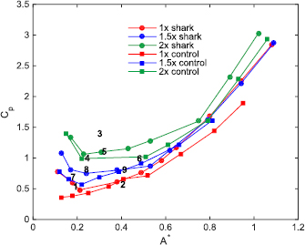
Figure 7. Measured Cp (coefficient of power) as a function of motion (which is considered here to be dimensionless tip-to-tip amplitude, A* = A/L) at a self-propelled speed corresponding to a Reynolds number based on the foil chord (ReC) of 3 × 10⁴ for the six different foils considered in this study (3 biomimetic shark skin foils as well as their 3 corresponding controls). The 1–9 numbered markers in the plot above show the location on this Cp versus A* plane of where the testing parameters were chosen for each of the foils for the other type of dynamic testing (i.e. finding self-propelled speed for a given locomotion). Tables 2–4 provide the testing parameters and results corresponding to these 1–9 numbered marks. Note that some A* values were challenging to obtain due to the high pitch frequencies and amplitudes required that could damage the robotic flapping device and/or the force transducer, and these experimental parameters were not tested.
Download figure:
Standard image High-resolution imageThe 1× denticle foil always had a higher COT than its respective control, although the COT values for the 2 Hz tests were not significantly different. For the 1.5 × and 2 × denticle foils, one motion program had a lower COT for each (2.5 Hz and 1.5 Hz respectively), while the other tested motion programs resulted in a higher COT for the denticle foils. The 1.5× denticle foil performed best relative to the control when tested at 15° pitch and 2.5 Hz in the sense of having both a higher SPS and a lower COT, although the 1× denticle foil had a higher SPS with an equivalent COT compared to its smooth control foil at 2 Hz.
Figure 7 shows power curves with the power coefficient for each denticle foil and its control plotted against dimensionless amplitude A* = A/L of trailing edge undulatory motion. All curves represent conditions of self-propulsion, and follow roughly the same pattern: a region of low power consumption (where Cp is lowest) around A* = 0.1–0.3 when self-propelling at ReC = 3 × 10⁴, and increasing power consumption when the imposed motion program generates large trailing edge amplitudes. The tight range of 0.1–0.3 for non-dimensional trailing edge amplitude is associated with optimal swimming at cruise condition as discussed by Saadat et al (2017). The values for optimal trailing edge amplitude obtained here fall in the range of observed tail-beat amplitude for diverse species of fish under the free swimming/self-propelled condition (Saadat et al 2017). Most curves initially start with a slightly larger power coefficient before decreasing to a minimum power region. In figure 7, denticle foils always have a higher power coefficient at any given motion (A*) compared to their respective controls. Thus, it appears that at this moderate self-propelling speed, the smooth controls are swimming more efficiently in terms of power use than their corresponding denticle foils.
Figure 8 illustrates dimensionless speed contours for tests at ReC = 3 × 10⁴ for the 1 × and 2 × denticle foils and their controls of the same mass. These curves present the complete kinematic envelope for our flapping foils at cruise condition whereby frequency and amplitude are controllable parameters (inputs) and the speed is a dependent variable (outcome). The choice of non-dimensional amplitude (A* = A/L) and frequency (f * = fL/U) arise in the dimensional analysis of a cruising swimmer as presented in Saadat et al (2017). One aspect of the locomotion studied here shown by figure 8 is the constancy and independence of Strouhal number of the motion from the kinematics of the flapping when A* is maintained at a value around 0.2. The constancy of St results in cruising speed being linearly related to the frequency of flapping. For dimensionless amplitudes, A*, below 0.4, there is a clear mass effect with the larger denticle foil and its control producing higher relative trailing edge motions at all f * = fL/U. For these experiments, biomimetic shark skin surfaces are not distinguishable from their smooth controls.
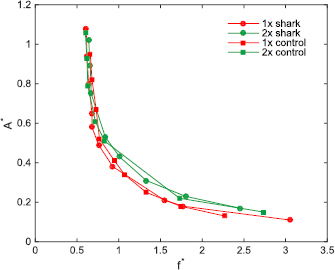
Figure 8. Dimensionless speed contours (dimensionless tip-to-tip amplitude A* = A/L versus dimensionless frequency, f * = fL/U) for the 1× and 2× shark skin foils and the corresponding control surfaces at a self-propelled speed corresponding to a Reynolds number based on the foil chord (ReC) of 3 × 10⁴.
Download figure:
Standard image High-resolution imageThe same procedure that was used to measure the power coefficient curves for all of the foils at the moderate Reynolds number based on the foil cord (ReC = 3 × 10⁴) shown in figure 7, was also used for a higher self-propelled speed (ReC = 5.3 × 10⁴): the results for this higher self-propelled speed are shown in figures 9 and 10. In figure 9, the power coefficient is plotted at various A* values for the 1× denticle and control foils at both the previously reported moderate speed (for comparison) and also for the higher self-propelled speed. At this higher ReC, several of the 1× denticle foil power coefficients were lower than their respective controls at the higher A* values between 0.5 and 0.7. These results indicate that the 1× denticle foils are consuming lower power while swimming than their respective controls at motion programs that generate higher trailing edge amplitudes. Figure 10 shows dimensionless speed contours for tests at ReC = 5.3 × 10⁴ for the 1× and 2× denticle foils and their controls of the same mass. In general, for higher values of A*, the 1× denticle foil swam with lower f * than its corresponding control.
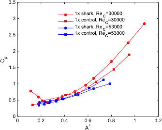
Figure 9. Measured Cp (coefficient of power) as a function of motion (dimensionless tip-to-tip amplitude, A* = A/L) at self-propelled speeds corresponding to Reynolds numbers based on the foil chord (ReC) of 3 × 10⁴ and 5.3 × 10⁴ for the 1× foils.
Download figure:
Standard image High-resolution image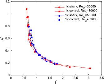
Figure 10. Dimensionless speed contours (dimensionless tip-to-tip amplitude, A* = A/L versus dimensionless frequency, f * = fL/U) for the 1× shark and control foils at self-propelled speeds corresponding to a Reynolds number based on the foil chord (ReC) of 3 × 10⁴ and 5.3 × 10⁴.
Download figure:
Standard image High-resolution image
4. Discussion
We found that denticle-containing foils performed better with smaller denticles and at higher SPS when tested dynamically, and we identified several conditions of frequency and leading edge pitch at which the denticle foils swam with a higher self-propelled speed (SPS) as well as with lower energetic COT than their corresponding smooth controls. These results demonstrate that even though foils with denticles on their surfaces have more than twice the total surface area of smooth controls of equivalent mass due to the presence of denticles, there are still motion parameters and denticle size combinations that result in improved swimming performance. Furthermore, despite findings in the computational literature suggesting that shark denticle shapes on a membrane surface produce increased drag (Boomsma and Sotiropoulos 2016), we measured significant drag reduction relative to smooth controls during static tests for the smallest denticle size, while increasing denticle size on the foils resulted in higher drag relative to smooth controls.
Despite the new functional insights gained from the present study, two overall limitations stem from (1) current constraints on the size limits at which small shark denticles and flexible membranes can be accurately 3D printed together, and (2) our inability to test dynamically under conditions of both high flapping frequencies and large pitch amplitudes at high Reynolds numbers. In these studies, we 3D printed the 1× denticles at the smallest size at which the final 3D printed denticles (figures 3 and 4) still retained sufficient detail to approximate those found in real shark skin (figure 1; Ankhelyi et al 2018). While the resulting morphology of the 3D printed denticles was biologically accurate, their larger size resulted in a corresponding increase in surface roughness from 150 µm for the 1× foils to 363 µm for the 2× foils. Attempts to print denticles at smaller sizes resulted in unacceptably distorted surfaces that did not resemble shark skin closely. Surface roughness of our 3D printed biomimetic shark skin foils also exceeded that of real shark skin. Measured biological shark skin roughness (Sq) values ranged from 15.1 µm to 33.4 µm (figure 1), while the biomimetic shark skin foil surfaces had surface roughnesses that varied from 150 µm to 363 µm (figure 4). In addition, the maximal pitch motor torque of our experimental flapping system limited the extent to which we could impose rapid high amplitude motion to the leading membrane edge and execute flapping at high Reynolds numbers (Re), which restricted our dynamic tests to a maximum Re of 5.3 × 10⁴.
Shark species vary widely in denticle size and shape (figure 1; Castro 1983, Reif 1985, Lauder et al 2016, Ankhelyi et al 2018), and we believe that our results both represent the range of effects of a denticle surface on swimming dynamics, and point toward future analyses with smaller denticles when manufacturing capabilities allow for such. Shark denticles vary from around 210 µm in length in mako sharks, to almost 1 millimeter in gulper sharks (Ankhelyi et al 2018). Many species have denticles in the range of 300–600 µm. Thus, while the smallest 1× denticle size tested here is still nearly twice the size of larger shark denticles, our results, with caveats, still suggest that smaller denticles confer hydrodynamic benefits. It should be noted, however, that the hydrodynamic effects of different sized denticles may not change dramatically with denticle size alone, as such effects will be dominated by the boundary layer thickness length scale. Boundary layer thickness, orthogonal to the denticle surface, can vary considerably during complex motions, and as such, is highly sensitive to both SPS and body oscillation, which induces complex fluctuation in the thickness length scale (see Yanase and Saarenrinne (2015)). It is thus difficult to determine just how denticle size alone will affect boundary layer thickness in the absence of direct measurements of the boundary layer over biomimetic shark skin membranes. Preliminary measurements of this kind were presented for biomimetic shark skin by Lauder et al (2016), but boundary layer thickness was not quantified over a body oscillation cycle relative to that on a control surface.
4.1. Static drag reduction by denticles
Our results are generally similar to those reported by Wen et al (2015), whose tests on a biomimetic staggered-overlapped shark skin foil exhibited reduced drag in static testing. We see a similar trend in drag reduction with the 1× denticle pattern described here, which exhibits reduced drag at lower flow speeds, and increased drag at faster flow speeds (figure 5). Since all tested foils with different denticle sizes have the same Reynolds number based on the foil chord (ReC), the different patterns of response to increasing flow that we observed for the three foils with differently sized denticles cannot simply be attributed to ReC. The foil with the smallest denticles (1×) is the only one that exhibited drag reduction, and both foils with larger denticles never showed a reduction in drag relative to a smooth control (figure 5). Reynolds numbers for the three tested foils (1×, 1.5×, and 2×) based on denticle size (ReD) varied from 200 to 1000, 300 to 1500, and 400 to 2000 respectively, and it is reasonable to expect that as denticle fabrication at smaller and smaller length scales becomes possible, drag reduction may also become evident at higher free-stream flow speeds. For a 1 m length shark swimming at a speed of 1 m s−1, the ReD ranges from 150 to 600 for denticles of 150 µm–600 µm in size. This contrasts to a whole animal Re using body length as the characteristic length of Re = 1 × 10⁶ or greater at high shark SPS. The smallest 1× denticle foil at the slowest test speeds thus has ReD values that are only slightly higher than the ReD of the mako shark based on its denticles, a value at which, we observe the best drag reduction in this study (figure 5).
A recent report that examined the role of ridged surfaces on drag reduction (Raayai-Ardakani and McKinley 2017) used a numerical approach to show that using the chord Reynolds number alone is not a good metric for evaluating drag reduction. These authors define a new Reynolds number (Reλ/L) that was based on chord length L and the wavelength between adjacent ridges, λ. Raayai-Ardakani and McKinley (2017) showed that at slower speeds and with certain ridge aspect ratios (the ratio of two times the height of the ridge to the wavelength between ridges), drag forces were reduced relative to a smooth surface. The study also showed that for chord Reynolds numbers greater than 104 (which is in the range of speeds tested in this study), values of unity for this aspect ratio tend to be best for drag reduction. Based on the images shown in figures 1 and 4 comparing shark denticle patterns to that of our biomimetic foils, if we assume that ridges as defined by Raayai-Ardakani and McKinley (2017) are equivalent to the pattern and spacing of middle denticle ridges on sharks, we note that the aspect ratios of both the biomimetic denticles as well as the biological denticles is roughly unity. Although there are many differences between the 3D denticle morphology in sharks and the long continuous triangular ridge used by Raayai-Ardakani and McKinley (2017), it is noteworthy that our foils function in the general region of Reλ/L identified by Raayai-Ardakani and McKinley (2017) as a drag-reducing zone.
The recent study of Boomsma and Sotiropoulos (2016) has called into question the ability of shark skin and biomimetic shark skin foils to reduce drag compared to their smooth controls. Boomsma and Sotiropoulos (2016) used an immersed boundary method to compute flow over a shark denticle surface, and they estimated that a denticle surface increases drag by 44%–50%. This result is similar to the maximal increase that we observed for the largest (2×) denticle sizes (figure 5) but stands in sharp contrast to the reduction in drag seen experimentally for the 1× denticle foil both here (figure 5) and by Wen et al (2015). Despite these radically different outcomes, these simulations were run using the same denticle parameters as those of the biomimetic surfaces that reduce drag both in our present study and those of Wen et al (2015). It is important to note, however, that the employed methods deviate from each other in that their Reynolds number (2800) was much lower than the lowest Reynolds number used in the present study, a slow speed that we were unable to precisely test with our current flow tank setup and force transducer. Although there are many differences between the computational domain of Boomsma and Sotiropoulos (2016) and the experimental configuration and free-stream speeds tested here, the differences in results are nonetheless perplexing. Boomsma and Sotiropoulos (2016) do compute a drag reduction of 5% for riblet configurations in general accordance with previous experimental data (Bechert et al 2000, Bechert and Hage 2007, Dean 2011), so the lack of concordance with the experimental demonstration of drag reduction with biomimetic denticle surfaces demonstrates the complexity of these interactions and needs further study.
4.2. Dynamic testing of propulsion
The importance of using dynamic tests for understanding the function of shark denticle surfaces has been emphasized previously by Wen et al (2014, 2015) and Lauder et al (2016). Although Domel et al (2018) recently shed light on the effects of denticle morphology on vortex generation on airfoils, all tests in that study were carried out under static conditions with the airfoil at a range of (fixed) angles of attack. To obtain a more complete picture of the hydrodynamic function of denticles, dynamic tests are needed as denticles experience dynamic flow conditions when sharks swim with undulatory propulsion. Testing under conditions of propulsion in which the denticle-embedded surface deforms during undulatory motion and undergoes cyclic curvature which interacts with free-stream flow is more biologically relevant to shark locomotion than static testing alone, in which the shark skin models do not move. The surface of swimming sharks undergoes changes in angle of attack throughout a tail beat cycle during locomotion (Webb and Keyes 1982, Donley and Shadwick 2003, Lauder 2006, Shadwick and Gemballa 2006, Lauder and DiSanto 2015), and so testing of shark skin effects should include conditions that mimic these time-dependent flow conditions as closely as possible. Also, comparison of water flow patterns between static tests and flapping propulsion by Lauder et al (2016) revealed considerable differences between the two types of testing, and suggest that flow alteration on the skin surface by denticles changes substantially when motion of the surface occurs. In particular, flow in and among denticles was greatly reduced during many phases of the flapping cycle compared to static test conditions (Lauder et al 2016).
Although the vast majority of literature on shark skin denticles addresses the possibility of drag reduction as a result of the roughened surface, both Oeffner and Lauder (2012) and Domel et al (2018) have demonstrated that denticle surfaces can alter thrust and lift forces and hence affect propulsion by affecting the formation and position of separation bubbles on the skin surface. The effects of denticle shape and arrangement on lift and thrust have yet to be comprehensively explored, but based on this previous work, we might expect that the effects of dynamic testing under conditions of denticle surface motion could reveal different effects and patterns of denticle size than emerge from static tests alone. It is also worth noting that we are not able to quantitatively compare changes in COT and power consumption between previous work on the propulsion of real shark skin samples (Oeffner and Lauder 2012) and the biomimetic foils studied here, as force and power were not measured in the previous research on propulsion of real shark skin. As such, additional experiments on the propulsion of real shark skin samples and the alteration of surface configuration while measuring power consumed during swimming are required and are an active area of ongoing research.
The dynamic tests conducted here, with several combinations of leading edge pitch and frequency at two SPS, result in undulatory propulsion of the manufactured denticle foils that permit calculation of locomotor self-propelled speeds as well as efficiency and COT (Saadat et al 2017). Our results show that the effect of denticle size and Reynolds number (ReC) on propulsion vary with the imposed motion program. For some combinations of size, pitch, and frequency, the denticle foils demonstrated a slower SPS than their corresponding smooth control and a higher COT (tables 2–4): for the two largest sizes of denticle surfaces, five of the six tests showed reduced SPS by the denticles compared to their smooth control, while one test showed equivalent swimming performance. However, for the 1× denticle size, all three test conditions resulted in improved denticle foil SPS relative to the control. These results suggest that the larger denticle sizes result in either increased drag or reduced effects on lift and thrust, or both, that reduce swimming performance relative to a smooth control.
When the flexible membranes of the biomimetic shark skin foils bend during undulatory propulsion, individual denticles can interact with each other due to their close proximity and tightly packed and overlapping pattern (figures 3 and 4), and such interactions might be expected to increase the COT depending on the imposed motion program (Wen et al 2015). Our results show that many of the motion programs and denticle sizes result in increased swimming costs (tables 2–4) and that this effect is not dependent on denticle size, at least for the sizes tested here. Five of the nine tested experimental conditions resulted in increased COT, two were equivalent between the control and denticle surface, while two tests showed reduced COT of denticle surfaces relative to their smooth control. Only one test, the 1.5 × foil at 2.5 Hz and 15° pitch, generated both increased SPS and reduced COT for the shark skin surface. Motta et al (2012) and Lang et al (2014) have noted that for mako sharks, the denticles are passively mobile within the skin and that denticles may change orientation based on surface flow characteristics. But another possible explanation for shark denticles that are flexibly embedded within the skin is to reduce COT, which results from bending the skin during undulatory propulsion. Denticles on real shark skin can overlap considerably (figure 1) and skin curvature that occurs during body bending would result in increased energetic cost if denticles were rigidly embedded. In our manufactured denticle membranes, however, the modulus of the basal substrate to which the denticles were embedded was not low enough to facilitate such mobility. While this may be the case, future advances in the multi-material additive manufacturing of elastomers with moduli in the kPa range could be used to test this COT hypothesis in biomimetic shark skins by directly altering the extent to which individual denticles can move relative to the skin surface.
Our measurement of swimming kinematics and power requirements followed the procedures outlined in Saadat et al (2017) who suggested plotting power coefficients against non dimensionalized trailing edge amplitude A* (A/L) and frequency f * (fL/U) to capture the dynamics of undulatory propulsion. The data on the biomimetic and control foils' propulsion (figures 7–10) show that size effects dominate differences between the smallest and largest foils. It is not surprising that power requirements should increase with foil mass (for both the denticle and smooth control foils), and that as foil inertia increases during flapping propulsion, the power required to swim at a given speed also increases. Denticles on the foil surface also change the power required for the foils in most of the tests, and as a result, power coefficients for denticle foils are generally higher than for controls at a given value of A* at the lower ReC tested (figures 7 and 8). However, when the smallest denticles (1× size) were tested at a higher self-propelling speed, we observed that for some motion programs, this denticle foil used less power to swim than its respective control (figure 9). We predict that as testing becomes possible at higher ReC values that begin to approach that of large sharks swimming rapidly (on the order of 500 000 or so) and as our ability to manufacture smaller denticles improves, we will see a greater reduction for the biomimetic foils in power consumption relative to smooth-surfaced controls. These results that showed that power requirements increased with foil mass also suggest that there may be natural selection for reduced denticle mass in rapidly swimming sharks and that the thin and flattened crowns of mako and white shark denticles, for example (figure 1), may act to reduce power requirements of bending the body during swimming by reducing denticle-denticle interactions in concave regions during undulation.
Finally, when both the static and dynamic test results are considered together for the biomimetic denticles tested here, we find that drag reduction (static tests) is improved at low speeds, while improved propulsion (dynamic tests) occurs at higher ReC and higher flapping frequencies. These results suggest that denticles may have different hydrodynamic functions depending on body orientation (and hence the local fluid environment) and locomotory style. The fluid environment around the body of a swimming shark varies tremendously over the head, tail, pectoral fins, and different body regions (due to the tilted swimming postures common in many sharks) and likely have differing turbulence levels and differing patterns of flow separation that change as the body and fins move (Wilga and Lauder 2000, 2002, Anderson et al 2001, Lauder and DiSanto 2015). Differing levels of oscillatory amplitude along the shark body from head to tail are also likely to impose different hydrodynamic conditions on the skin, although specifics of how flow varies in the near skin region around the body are largely unknown (Anderson et al 2001).
Different locomotor behaviors such as steady swimming, gliding, accelerations, and rapid turning maneuvers also are all likely to result in altered flow patterns at any one location on the body, and the static and dynamic results reported here may provide insight into different aspects of shark locomotion. Our static drag testing results may be most relevant to slower speed gliding behavior where the body is held relatively steady, while our dynamic testing results may be more relevant during undulatory locomotion. These two modes of locomotion are commonly used in conjunction with one another during normal shark swimming as can be observed when a shark will tend to move quickly and dynamically to generate thrust and then glide following a bout of undulation. Our dynamic testing results may also reflect changes in both thrust and lift and drag forces generated by denticle surfaces under dynamic motion (see also Domel et al (2018)). The changing angle of attack that denticles experience as the shark body undergoes undulatory locomotion is reflective of the dynamic tests here as the denticle surface of different regions of the swimming foils experiences time-dependent changes in incident flow. Because denticle structure, which exhibits site-specific variability across the body surface (Reif 1985, Ankhelyi et al 2018), may reflect a functional compromise that reflects both dynamic and static flow patterns, there remains considerable scope for future research to develop an understanding of precisely how and why different denticle surface structures affect flow, and how flow varies in the near-skin region during swimming. The results presented here not only provide important insight into shark locomotor hydrodynamics, but also provide conceptual guidelines for the design of aquatic or aerial bio-inspired robots. More generally, any dynamic system moving through a fluid medium could potentially benefit from both drag reduction and thrust enhancement through the incorporation of these shark-inspired surface coatings.
Acknowledgments
The authors would like to thank Harvard University's John A Paulson School of Engineering and Applied Sciences, as well as the Wyss Institute for support. G V L acknowledges the support of the Office of Naval Research grants N00014-09-1-0352 and also N000141410533. K B gratefully acknowledges support by the National Science Foundation through grant DMREF-1533985. Many thanks to Connor White for providing the leopard shark specimen, and to Dylan Wainwright and Madeline Ankhelyi for assistance with measuring surface profiles in the shark skin and biomimetic membranes in figures 1 and 4.