

Abstract
The Jupiter Observing Velocity Experiment (JOVE) is a solar-powered technology demonstration of rapid flight to outer solar system targets, performing a flyby of Jupiter 30 days after launch. This is achieved using a magnetic drag device to accelerate with the solar wind plasma. This "Wind Rider" propulsion system can potentially also decelerate against the Jovian magnetosphere dawn eddy, to enable Jupiter orbital insertion in future missions. The 16U cubesat bus contains scientific instruments to record the plasma parameters from the vicinity of the spacecraft, with principal measurements coming from a SPAN-I ion velocity sensor. This paper includes a description of the propulsive mechanisms and supporting subsystems and trajectory simulation results derived from solar wind measurements over the past two solar cycles. The objectives of the JOVE technology demonstrator design include: (1) verify Wind Rider stability and control; (2) characterize loss mechanisms in the solar wind, such as resistive losses in the plasma, as well as the magnetic field transient interaction time; (3) operate onboard instruments to measure the velocity and direction of the solar wind (SPAN-Ai) and speed of the spacecraft relative to the Earth (radio Doppler shift), to enable precision navigation on future science missions; and (4) characterize the Lift-to-Drag ratio of the plasma magnetic field. (The lift force enables lateral course control and maneuvering within the solar wind.) Applying existing scientific data from Voyagers and other deep space probes into new engineering models was important for enabling new insights about Wind Rider propulsion. It enables more science to be performed in a shorter amount of time, across the Jovian system.
Export citation and abstract BibTeX RIS
1. Introduction
1.1. Wind Rider Background and Prior Ground Experiments
The Wind Rider uses superconducting rings approximately 9 m in diameter to create a large-scale plasma bubble, tens of kilometers in diameter, that can interact with the solar wind or a planetary magnetosphere, producing significant drag force. The coils generate a rotating magnetic field (RMF) that inflates the plasma structure, which consists of a plume and wake as diagrammed in Figure 1.
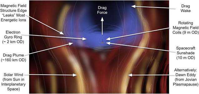
Figure 1. Wind Rider, Solar Wind Drag Device Concept (Not to Scale).
Download figure:
Standard image High-resolution imageThe Wind Rider spacecraft concept is based on the Plasma Magnet (Slough & Giersch 2005; Slough 2006, 2007) as a means of intercepting a propulsively useful, large area of solar wind momentum with modest driving coils. The principle is that a pair of coils, perpendicular to each other and mutually perpendicular to the wind axis, are driven by alternating currents 90° out of phase with each other, generating a RMF. The frequency of rotation is chosen to be well below the electron gyrofrequency of the freestream solar wind plasma and its associated magnetic field; therefore, the electrons are pulled around by the RMF a circulating current loop, the axis of which is aligned with the wind. Initially, the magnetic pressure in that current loop, driven by the RMF, is greater than the sum of the dynamic pressure of the solar wind and the magnetic pressure of the interplanetary magnetic field (IMF), so the loop expands—entraining additional electrons from the solar wind plasma as it does so—until the magnetic pressure of the current loop just balances the external sources of pressure. The frequency of rotation of the RMF must be above the ion gyrofrequency within the current loop perimeter so that the ions do not set up a canceling current by moving counter to the electron flow. The electron current, then, appears as a quasi-static magnetic field to the approaching solar wind ions, which do not respond to the oscillatory RMF component above the ion gyrofrequency, and the electron current loop deflects the solar wind much as would a conventional magsail (Andrews & Zubrin 1990) but of very large radius. The effective radius of the current loops is the radius of the driving coils times the ratio between the magnetic field strength of the driving coils and the magnetic field strength of the expanded sail in equilibrium with external sources of pressure—and that ratio can be very large (many orders of magnitude). The resulting structure in practical terms has a radius larger than 10 km.
The force generated by the Wind Rider device is limited by the input power from the spacecraft to the coils (overcoming losses in the superconductors) and the diameter of the coils; packaging the coils becomes impractical as they get larger. Operationally, the Wind Rider is limited by the solar wind speed and direction. Drag devices only work in the "downstream" direction. In the case of our Jupiter mission, this means launch must wait until Jupiter is in opposition. Finally, there are unknowns in how steerable the device will be.
The Wind Rider drag device has a lengthy history of experimental development on the ground. After Slough and Kirtley's initial development for NASA including demonstrations in a "solar wind tunnel," there were several attempts to develop an in-space demo for Earth orbit. Slough (2006), Kirtley (2012) A tech demo mission named MIDAS by Altair Space Machines Altius Space Machines (2014) was followed by an effort to dispense a Magnetoshell Aerobraking CubeSat (MAC) from the ISS by UW Master's student Kelly. Kelly (2018) There are scale-down challenges when using this approach for a spacecraft as small as a 3U Cubesat and inside the Earth's magnetosphere, which has a magnetosphere co-rotational velocity of only 1.5 km s−1. Bagenal (2013) Slough's ground experiments indicate that the Wind Rider device works at a larger scale. Slough (2006) Outside the Earth's magnetosphere, Wind Rider can operate on the solar wind which exceeds 340 km s−1, the regime we chose for Jupiter Observing Velocity Experiment (JOVE). The JOVE is a new design to test Wind Rider in interplanetary space via a 16U microsatellite.
1.2. Concept Overview
JOVE is a 16U microsatellite that will use Wind Rider for a test flight past Jupiter orbit taking only 30 days. This provides a benchmark for achieving a 5 au distance with no gravity assist; JOVE will reach a velocity near 300 km s−1 under Wind Rider power alone. JOVE has enough battery power to test magnetic braking near Callisto, but not to stop or enter orbit; this is a one-way trip (flyby). An upper stage provides escape velocity at mission start, deploying JOVE into a Cis-Lunar initial orbit. A rendering of the deployment steps is shown in Figure 2, where the two high-temperature superconducting (HTS) coils stretch out on a boom, followed by the solar panel arrays and sunshade (visible in Figure 3).

Figure 2. JOVE model pre- and post-deployment of the HTS coils. The mast is 9 m long.
Download figure:
Standard image High-resolution image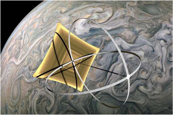
Figure 3. Full-scale Wind Rider implementation at Jupiter with sunshade. The coils are shown illuminated for clarity but in practice they will be shaded. The sunshade as shown measures 10 m along the diagonal, while the coils have a 9 m diameter.
Download figure:
Standard image High-resolution imageOnce the sunshade and solar panels are deployed, JOVE spends about 24 hr calibrating instruments before activating the RMF inside the two coils. It then departs from the initial Cis-Lunar orbit via Wind Rider toward the Jovian system. The concept of operations summary for JOVE is as follows:
- 1.Q4 2023 or Q4 2024 launch
- 2.Accelerate for 24 days to 300 km s−1
- 3.Pass Jupiter at closest approach on day 25
- 4.Decelerate for 1 hr inside Jovian magnetosphere
- 5.Mission ends on day 30.
A simple telemetry beacon will be operated by battery for most of the cruise phase, which might last beyond 5.2 au. Secondary objectives for the tech demo are to demonstrate steering, up to half a degree below the ecliptic plane; and deceleration in Jupiter's dawn eddy (to be discussed later). Without steering, JOVE crosses over the north pole of Jupiter as soon as 19 days after departing Cis-Lunar orbit. As mentioned previously, a sunshade to protect the superconducting coils is necessary at 1 au; while it is no longer necessary for thermal management at Jupiter (5.2 au), due to the much lower solar flux, it also serves as a thin sheet antenna providing S-band radio back to Earth. Thus, the "sunshade" is retained onboard for the full 30 days mission duration.
The electron cyclotron frequency is set by the solar wind parameters, but to match it, an EMF coil's inductance must be tuned. The shape and placement of the HTS strips impact the coil's inductance, at a large EMF coil diameter scale, leading to the choice of a flat conductor (not round wires). The principal current flows through the circuit, so it must be tuned without a matching capacitor in parallel. This also determines the maximum coil size. Likewise, the capacitance is twice the self-capacitance, due to a power supply match. Impedance can be matched using transformers or capacitors in series. In practice, JOVE's coils will use a 4 Hz frequency, which is slightly higher than the ion cyclotron frequency.
The larger the coil radius, the more it is limited by inductance (to reach the resonant frequency with the surrounding plasma), and then torque (buckling or structural issues). As for scaling down, the smaller the coil radius, the more it is limited by input power to achieve an equivalent drag force. For this paper, a trajectory seed code (discussed in Section 1.3) was used to optimize the coil radius, based on the internal losses (due to hysteresis) equaling the plasma losses (due to resistance). Finding this null derivative in the curve also causes the coil to occupy the design regime between the lower and upper bounds. JOVE's coils are optimized for use in the solar wind at 1 au.
The amount of lift to drag ratio is unknown and, to be conservative, is assumed negligible in the Mathcad trajectory seed code used to generate feasible trajectories. If that turns out to not be the case, based on experimental data from the technology demonstration telemetry, then further steering control would be enabled by the reaction wheel assembly offsetting the CG further from the radial direction of flight from the Sun.
1.3. Trajectory Seed Code Models
A trajectory seed code was written in Mathcad 14 R020. It is comprised of six modules, the main three of which are discussed in further detail here.
1.3.1. Solar Wind Model
Solar wind plasma parameters using NOAA data from the last 22 yr (2 solar cycles) were averaged to create consistent solar wind starting conditions for each trajectory away from Earth orbit. NOAA (2021) At 1 au, those averaged values are as follows.
- 1.Ion Speed: 430 km s−1
- 2.Ion Density: 3.3 cm−3
- 3.Ion temperature: 12.5 eV
- 4.Magnetic Field: 0.7 nT.
The minimum and maximum of these values over the same time period were also included in our seed code, as well as variability between the electron to ion temperature. The direction of the solar magnetic field is not considered by the seed code; only the magnitude is utilized. That extra information is reserved for more advanced, professional trajectory simulation software to incorporate for a more detailed trajectory model.
A radius-varying Solar Wind model was created using additional data from Voyager plasma data, Richardson et al. (2019) and Richardson (2021), as well as other sources of space weather direct measurement and simulation. For example, the solar wind temperature and particle density versus distance from the Sun was linearly interpolated between 1 and 21 au, from 12.5 eV at Earth (Newbury et al. 1998; Elliott et al. 2019). For the local plasma density, this radial-model was extended to a value beyond the (123 au) heliopause, using an experimentally measured and corrected value of 0.127 particles cm−3 (Kurth & Gurnett 2020; Swaczyna et al. 2020). Similarly, a radially varying magnetic field model was also included (Burlaga et al. 2002; Usmanov & Goldstein 2003).
1.3.2. Wind Rider Model
The following are the core equations governing the Wind Rider subroutine in the trajectory seed code. vw is wind speed in heliocentric coordinates, which is a function of distance r from the Sun and angle ϕ above the ecliptic plane. ur is the radial velocity of the spacecraft. Rrw is the radius of the plasma plume, typically 60–100 km. The radius of the coils, Rcoil, is 4.5 m on JOVE. Zw is the effective charge of the solar wind.
Dynamic pressure of the solar wind, DynP:

where mi is the average ion mass and np is the solar wind particle density.
Magnetic pressure, MagP, of the interplanetary magnetic field, Bimf:

Thrust from solar wind drag-force on Wave Rider, Fwr:

The magnetic field equivalent inside the Wind Rider, Bwr, is computed from the dynamic pressure plus the magnetic pressure from the free-stream interplanetary field:

Magnetic field Bcoil at the center of the Rotating Magnetic Field coil:

Current in circular coil:

The RMF frequency f must exceed the ion gyrofrequency within the electron current loop. The engineering constraints of the superconducting coils favor a low operating frequency to minimize hysteresis losses within the superconductors. We have limited the minimum operating frequency to 5 times the ion gyrofrequency measured within the near-spacecraft magnetic field. This may be excessively conservative and in-space characterization of how low the driving frequency can go before reducing the effective drag of the sail would be a desirable result of this JOVE mission

These core equations are based on the published work of Slough (2006). The input parameters for each of these equations come from the local solar wind plasma environment. To calculate the solar wind pressure correctly (to estimate the local drag force on the Wind Rider coils), it is important to not assume that the solar wind consists of only protons, but to use the average atomic mass of the actual solar wind composition. The same approach is used for the effective charge or average ion atomic number. This charge can affect the drag force calculations farther from the Sun, in the gradual transition from the foreshock (at 83 au) to the onset of interstellar space near the heliosphere boundary at 123 au. Also, the ion temperature in the solar wind versus distance from the Sun can fluctuate across the foreshock.
Electrons can be up to twice the local ion temperature, under fluctuating conditions even closer to the Sun, too. In addition, if the trajectory enters a magnetosphere of another planet, then the local environmental plasma parameters change in the simulation to address those differences in density, velocity and composition.
1.3.3. Magnetosphere Model
The IMF versus distance from Sun to the heliopause, as well as planetary magnetic field versus altitude when inside a magnetosphere, are modeled from reference data. Bagenal (2013) When the Wind Rider attempts to generate drag (to brake) inside the magnetosphere, the local parameters are estimated from models based on the analysis of Bagenal and Chane. Chane et al. (2013) In addition to the previously described three modules, the trajectory seed code also includes a basic Trajectory Solver, Plasma Diagnostics and Optimizer for Plotting numerous missions of interest to the scientific community.
1.4. Propulsion and Power Specification
With Wind Rider, launch opportunities to each planet occur annually. As JOVE's target is Jupiter the launch window is one month before Jupiter is at opposition: 2023 November 2 or 2024 December 7. (The solar maxima occurs in 2025 July.) JOVE can be deployed from an apogee of 60,000 to 90,000 km Sun-side or into Cis-Lunar orbit. The mission duration is 30 days total to achieve the primary objective, including an optional 5 days period at the end, to transmit images (or until the radio stops telemetry due to lack of solar power). At the end of the mission, JOVE will attempt to send a photofrom a witness camera showing Jupiter. An illustration of JOVE passing Jupiter is shown in Figure 3.
A brief summary of the Wind Rider specifications, bus capabilities, navigation hardware and scientific instrumentation is provided in Table 1. This list is not intended to be exhaustive, as this is an introductory paper, but representative of the quality of components, many of which have flown on previous deep space exploration missions. The specifications were compiled based on minimum requirements for JOVE, but also for follow-on missions that would likely need slightly better or more accurate instruments for their scientific objectives. In particular, the active cooling system, a Brayton cooler, is oversized for that reason and to provide extra margin during the technical demonstration flight of JOVE.
Table 1. JOVE Design Specifications
| Parameter | Description |
|---|---|
| Wind Rider | |
| Speed Rating | 300 km s−1 (∼63 au yr−1) |
| Coil Diameter | 9 m (2 RMF circular coils, 8U stowed) |
| Materials | Aramid/Kevlar composite coil substrate, Kapton thin sheet antenna, metallic thin film reflector (front-sunshield) |
| Superconductor | GdBCO flat-channel superconducting strips operated at 80 K (Wimbush & Strickland 2019) |
| Cryocooler | 4 W, 80 K reverse-Brayton cycle ULP from Creare (Zagarola et al. 2014) |
| Power Supply | AC up to 4 Hz at 112 A (in HTS circuit), resonance capacitors |
| Spacecraft Bus | |
| Size | 16U cubesat, KRATOS from EXA |
| Mass | 21.3 kg mass microsatellite bus |
| Power | 1300 W at 1 au, 50 W at 5.2 au |
| Battery | 1456 Whr battery pack array of TITAN-2/L4 from EXA (lined along walls) |
| Solar Arrays | 4 deployable panels from EXA, each 2 × 8 unfolded (rear-sunshield) |
| Radio | 256 bit s−1 minimum rate at Jupiter from S-Band antenna |
| Structure | Two 9 m diameter superconducting coil rings supported by 9 m mast |
| Navigation Hardware | |
| Avionics | ICEPS-K 8.5, Digital Module w/Z2 SDR (Nader 2019) |
| Radio | 9 m aperture antenna in S-band (speed from Doppler shift, 255 bit s−1 minimum at 5 au) |
| Reaction Wheel Assembly | HR04 (actuator feedback for steering) |
| Gyro | HG4934BA60 (rotation measurement) |
| Star Trackers | ST16R2 short baffle (18 deg s−1 spin star-blur limit) |
| Scientific Instruments | |
| Rearview Camera | Sinclair Interplanetary ST16R2 |
| Super Low Frequency Receiver | 50 Hz minimum from Sidekiq SDR spare Rx port, 5.65 m quarter wavelength from antenna |
| Solar Wind Velocity Sensor | UC Berkeley SPAN-Ai (Livi et al. 2021) |
Download table as: ASCIITypeset image
2. Flight Dynamics Overview
There are two separate torques that perturb the flight stability of the Wind Rider device. The first is a minor torque, τc , caused by the attraction of the coils to each other, which oscillates at the RMF frequency and is canceled out by the tension in the boom or supporting structure. However, there is some stretch in the structure, such that this minor torque causes a shift in the center of pressure Cp relative to the center of mass Cg .
Even flying straight and radially away from the Sun, this small perturbation (if left unchecked) causes the Wind Rider to tilt relative to the solar wind velocity vector, until it "capsizes" at 90°, as shown in Figure 4. Therefore, a counter torque is necessary when the Wind Rider is powered. Such feedback can be obtained from a reaction wheel assembly. It can also be used to offset the center of mass of the spacecraft from the direction of drag force, to provide some steering capability to the Wind Rider.

Figure 4. Solar Wind Tilt Stability, Illustrating a Wind Rider Capsizing (Nishida et al. 2005).
Download figure:
Standard image High-resolution imageAlthough flying with the Wind Rider coils oriented perpendicular to the solar wind shear (capsized) is stable, it is also much less efficient as the cross-sectional area presented is much smaller. This is shown in Figure 5. Note that at very close to zero angle of attack, the perturbing torque to tilt is also near zero. Thus, it is possible to offset this tilt with similarly small momentum wheel torque, so long as the angle of attack does not drift too far from zero.
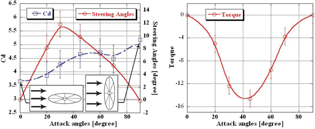
Figure 5. Angle of Attack Coefficient of Drag and Tilting Torque (Nishida et al. 2005).
Download figure:
Standard image High-resolution imageFor angles of attack larger than about 10°, the tilting torque eventually overpowers the reaction wheels' restoring torque and the Wind Rider capsizes. As this is a very stable angle of attack, the Wind Rider is locked in this position. A reset would be needed to overcome this situation, where the control algorithm would purposely shut down the RMF coils, the reaction wheels reposition the Wind Rider at zero angle of attack to the (radial) solar wind and then the coils are powered back up to resume acceleration. However, this all takes time. There can also be a momentum dump step during this procedure, if the reaction wheel assembly saturates, so it is best to avoid capsizing in the first place. Again, a small counter-torque should be applied from the reaction wheels to maintain a straight-line trajectory as the Wind Rider is accelerating.
Separately, there is a second torque τp on the entire spacecraft from the surrounding plasma, specifically the torus of electrons inside the plume. During the acceleration phase, the solar magnetic field subjects the Wind Rider's coils to this torque. The scale of the plasma is determined by the electron gyrotron radius which is approximately 1–2 km at 1 au. Although the mass is small, the total momentum of the torus is sufficient to put up to several hundred Newton meters of torque across the Z-axis centerline. Left unchecked, this torque will also tilt the coils perpendicular to the solar wind, until the Wind Rider capsizes. Our models estimate the first torque on the order of 5 Nm at an RMF frequency of 4 Hz and the second torque on the order of 100 Nm, at worst-case conditions. Just as there are mitigation strategies for desaturating a reaction wheel assembly, this area of research could be ripe for study on methods to minimize incident torque from the solar wind or the Sun's magnetic field. It is also an area of continued interest in the current study.
2.1. Trajectory Simulation Results
We have used the trajectory seed model in Mathcad, based on ephemeris tables that include all planets, many minor planets and examples of interesting asteroids for exploration. The dynamics model uses the Sun, Earth and destination gravity wells, in this case Jupiter. As previously noted in Section 1.3.1, the solar wind plasma parameters vary over radial distance from the Sun. The code has a Wind Rider optimizer, based on available power. The trip estimator requires maximum power, initial mass and final destination, which for this paper is Jupiter. The optimizer also locates the closest approach launch window within the next decade. Although this paper focuses on Jupiter as a destination for future orbiter concepts, similar conclusions can be drawn for other gas giants, such as Saturn. The results for JOVE's flight path are plotted in Figure 6. The Deep Space Probe (DSP) in this case is JOVE.
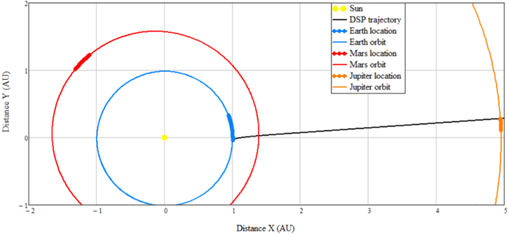
Figure 6. Trajectory from LEO to flying by Jupiter nominally takes 25 days.
Download figure:
Standard image High-resolution imageFuture work includes further optimizing the JOVE's trajectory in professional simulation software, such as the Astrodynamics Workbench. A sample screenshot using the seed code's output parameters as input is shown in Figure 7.
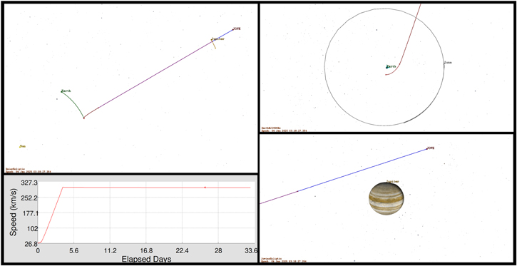
Figure 7. Example trajectory with Astrodynamics Workbench of Wind Rider to Jupiter, showing clockwise from the upper left the full trajectory, the Earth departure, the Jupiter flyby, and the Sun-centered speed of the spacecraft.
Download figure:
Standard image High-resolution imageThe Mathcad trajectory seed code also sizes the coils. The RMF coil radius (for 1 au) optimization depends on input power, which for JOVE comes from a solar panel array. The 9 m radius chosen for JOVE is a practical minimum for use in the Solar Wind at 1 au. However, that may not be the optimum at Jupiter, if attempting to decelerate inside the Jovian magnetosphere.
2.2. Wind Rider Magnetic Brake
Jupiter's magnetosphere provides a dense plasma, which makes deceleration with a Wind Rider practical. Figure 8 shows an equatorial cross-section of Jupiter's magnetosphere in which the dawn eddy is in the red region. JOVE will pass through with a close approach of about 10 Jupiter radii, as shown by the arrow, moving from left to right. Passing through the dawn eddy, with velocities over −600 km s−1 (in the opposite direction) will provide ample kinetic energy for braking. Orbital insertion is not required for mission success; JOVE need only show that it is possible to decelerate this way.
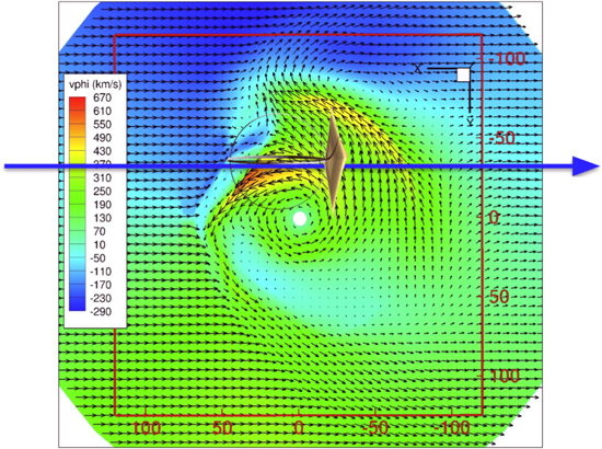
Figure 8. Bulk velocity in equatorial plane of Jupiter's magnetosphere with JOVE trajectory superimposed, Chane et al. (2013).
Download figure:
Standard image High-resolution imageNote that the co-rotational maximum velocity of the magnetosphere occurs for 12 hr, once every 30 hr (Chane et al. 2013). It is unlikely that JOVE can time this interval well on a first attempt. The batteries are sized to provide one hour of deceleration, which under ideal conditions might slow the spacecraft velocity by 5%. The data retrieved by JOVE during this process is invaluable scientific data for future mission designs, though. A much higher-powered spacecraft could slow to enter Jupiter orbit. If that process were repeated, the dawn eddy may enable up to 480 km s−1 velocity back toward the Sun, which opens up rapid access to the inner planets or a sample-return trip to Earth.
Ultimately, a larger radius set of coils may be more optimal for deceleration inside the Jovian replacedplasmapausemagnetosphere, but more input data (from the JOVE mission itself) is necessary to optimize braking maneuvers over a 12 hr "stop" to Jupiter orbital insertion. For reference, a 40 m radius is the current estimated manufacturing limit. For now, JOVE intends to fly with a single set of 9 m coils for all phases of its tech demo mission.
3. Data Gathering and Mission Instruments
Figure 9 shows the scientific instruments selected for JOVE. As discussed in the previous section, it is critical to measure the interactions during braking in the Jovian magnetosphere. The primary instrument to achieve that, the SPAN-Ai sensor from UC Berkeley, measures the properties of the solar wind, as well as the plasma inside the Jovian magnetosphere at the end of the mission (Livi et al. 2021).

Figure 9. Minimal Instrumentation on JOVE.
Download figure:
Standard image High-resolution image
There are also a pair of star trackers to measure orientation. An Inertial Measurement Unit (IMU) and gyroscope are part of the Guidance Navigation and Control (GN&C) suite. The spacecraft velocity relative to the Sun is determined by a radio science (Doppler shift) experiment, whose main antenna is shown stowed at the bottom of Figure 9. The bus design currently has space for two additional instruments, one inside and one outside the spacecraft, as indicated in the diagram.
All of these work together to help demonstrate and then precisely measure simple acceleration, in terms of a primary objective for the experiment, up to close to the solar wind speed. The primary objective is to achieve a velocity a little bit above 300 km s−1. In the future, larger spacecraft will be able to utilize a more capable instrumentation package, such as the 60 kg suite specified for the DSP (Freeze & Cassibry 2021).
4. Conclusions
Wind Rider, if successful, will enable launch windows once a year to destinations across the solar system, at vehicle speeds approaching the solar wind speed, which ranges from 340 to 560 km s−1 with an average of 430 km s−1. The basic concept of the Wind Rider plasma magnet has been demonstrated on the ground and the next step is an in-space flight test. The JOVE tech demo would demonstrate this propulsion technology with an unprecedented 25 days travel time to Jupiter. JOVE will gather data critical to maximize future Wind Rider capability, especially for steering, but also for braking at Jupiter. Future missions with higher power may be able to enter Jupiter orbit within the same trip time.
Only Jupiter's magnetospheric particle velocity exhibits a magnitude comparable to the solar wind velocity (Bagenal 2013). The other magnetospheres rotate too slowly to enable the same level of deceleration (or re-acceleration) for rapid trip times across the solar system, with the possible exception of Saturn or the Moon (while it orbits within the Earth's magnetotail). For Jupiter, the Wind Rider enables rapid missions to both the Galilean moons (Europa, Ganymede & Callisto), Taylor (2005), Bellerose & Yano (2010), Hubbard (2012), Howe et al. (2021) as well as the retrograde-orbit of Ka'epaoka'awela (Gold et al. 2007; Brown 2009; Namouni & Morais 2020).
This class of propulsion system enables SmallSat missions to a wide variety of outer solar system targets, opening up a range of previously unreachable science opportunities. The policymaking recommendations from the Practical Interplanetary Propulsion (PIP) Study are simple: support the launch and flight of the tech demo drag device on JOVE, and engage the scientific community on ways to encourage use of this technique in other deep space destinations or to enhance missions of interest, such as the ESA Comet Interceptor (Jones & Snodgrass 2019). For missions beyond 5.2 au, a power source other than solar energy will be required to operate instruments and transmit data back to Earth. Those missions require meaningful investment into radioisotope power systems and fission power systems for space (Sholtis & Lipinski 2022).
The Practical Interplanetary Propulsion (PIP) Study would not be possible without the support of the AIAA Nuclear Future Flight Propulsion (NFFP) section. The technical committee members of our group, their mentors and supporting advisors from both government and industry were instrumental in making progress this past year. This paper is the second in a series that summarizes the findings of the PIP Study. This content is contributed to AAS for publication in the Planetary Sciences Journal under the auspices of the AIAA Technical Activities Division.