

Abstract
The newly developed spherical smart aggregate (SSA) based on a radially polarized spherical piezoceramic shell element has unique omnidirectional actuating and sensing capabilities that can greatly improve the detection aperture and provide additional functionalities in health monitoring applications in concrete structures. Detailed fabrication procedures and electrical characterization of the SSA have been previously studied (Part I). In this second paper (Part II), the functionalities of the SSA used in both active sensing and passive sensing approaches were investigated in experiments and numerical simulations. One SSA sample was embedded in a 1 ft3 concrete specimen. In the active sensing approach, the SSA was first utilized as an actuator to generate stress waves and six conventional smart aggregates (SA) mounted on the six faces of the concrete cube were utilized as sensors to detect the wave response. Conversely, the embedded SSA was then utilized as a sensor to successively detect the wave response from each SA. The experimentally obtained behavior of the SSA was then compared with the numerical simulation results. Further, a series of impact tests were conducted to verify the performance of the SSA in the detection of the impact events from different directions. Comparison with the wave response associated with different faces of the cube verified the omnidirectional actuating and sensing capabilities of the SSA.
Export citation and abstract BibTeX RIS
1. Introduction
Piezoceramic-based transducers are particularly versatile for structural health monitoring (SHM) due to their low cost, fast response, availability in different shapes, suitability for energy harvesting and capabilities as both actuators and sensors [1–10]. Since bare piezoceramic patches are fragile and easily damaged when they are embedded in concrete structures, Song et al proposed an embeddable piezoceramic-based transducer called a smart aggregate (SA) which offers complete electrical isolation and sufficient load resistance by protecting the fragile piezoceramic patch with a solid case [11]. The first generation of SAs was designed by embedding the PZT patch with lead wires in a cast concrete block. Subsequently, to better improve the survivability of the embedded SAs when the concrete structure is overloaded, the second generation of SAs was developed by sandwiching the PZT patch between two marble blocks. Compared with the first generation of SAs in concrete, the second generation of SAs provides improved mechanical stability [12]. Based on different types (d33 or d15) of lead zirconate titanate (PZT) patches used in fabricating SAs, SAs can be made either compressive mode SAs [13] or shear mode SAs [14]. Compressive and shear mode SAs can generate or receive various types of stress waves (e.g. P or S waves, respectively) that significantly improve the suitability of the SA for detecting different types of damage in concrete structures.
Ever since SAs were first reported in the literature in 2006 [11], SAs have been increasingly used in SHM for detecting various types of damage in concrete structures, including detection of cracks due to static and seismic loads [15, 16], leak detection [13], bond slip detection [17], debonding detection [18] and impact detection [19]. In addition to the detection of damage (geometric change) in concrete structures, SAs have been applied to the real-time monitoring of change in material properties such as during concrete hydration processes [20] and soil freeze–thaw [21]. Current SA-based sensing technologies mainly include active sensing approaches [22], passive sensing approaches [23] and acoustic emission (AE) approaches [24]. In addition to the current SA-based sensing technologies, SAs also have the potential to be implemented with an impedance-based approach [25] for SHM. However, due to the geometry of the two-dimensional PZT patch embedded in the SA, the actuating and sensing capabilities of the SA are limited to within a certain aperture corresponding to the patch orientation. Figure 1 gives an example of stress wave communication using SAs to SAs and spherical smart aggregates (SSAs) to SSAs. It can be clearly seen that the omni-dimensional actuating and sensing capacities of the proposed SSA can help to reduce the number of the SAs deployed in the concrete structure. In addition, in many cases, if the location of the damages or impacts are unpredictable, typical deployment of SA sensing networks requires SAs to be installed in pairs with matching orientations so that an adequate detection aperture can be achieved. The limited directionality of SAs causes complications in transducer installation, wire management and data acquisition, all of which lead to additional labor and economic burden.
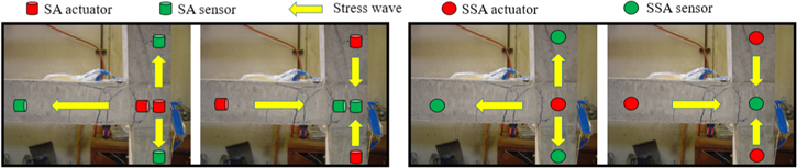
Figure 1. An example of SAs to SAs versus SSAs to SSAs.
Download figure:
Standard image High-resolution imageIn Part I of the paper we introduced the design of a novel embeddable SSA using a spherical piezoceramic shell and ultra-high performance concrete (UHPC) protection. The unique omnidirectional actuating and sensing capabilities of the spherical piezoceramic shell significantly improve the detection aperture of the proposed SSA in SHM. In addition, the SSA with UHPC protection has an unparalleled survival rate compared with current SAs when the concrete structure is overloaded. In this paper (Part II), the functionalities of the SSA were experimentally verified in two of the most commonly used piezo-based sensing methods, including active and passive sensing approaches. One SSA sample was embedded in a 1 ft3 concrete specimen. In the active sensing approach, the SSA was first utilized as an actuator and six conventional SAs mounted on the six faces of the concrete cube were utilized as sensors to detect the wave response. Conversely, the embedded SSA was then utilized as a sensor to subsequently detect the wave response from each of the SAs. The experimental results were compared with those from the numerical simulations using the numerical SSA model proposed in Part I. Further, a series of impact tests were conducted to verify the performance of the SSA in the detection of the impact events from different directions. A combination of the analytical study of the influence of the dimensions on the natural frequencies of SSA (Part I) and the further functionality verifications (Part II) provides a general design guideline for SSAs and demonstrates the potential of SSA in future SHM applications.
2. Constitutive equations of the spherical piezoceramic shell
The piezoelectric element in the SSA is a radially polarized hollow spherical piezoceramic shell. It has uniform electrodes on both the sphere outer surface Ro and inner surface Ri. To lead the wire welded on the inner surface to the outside, a small hole with a diameter of 2 mm is reserved. A spherical coordinate system ( ) with the origin located at the center of the spherical piezoceramic shell is established, as shown in figure 2.
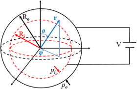
Figure 2. Schematic of a radially polarized spherical piezoceramic shell.
Download figure:
Standard image High-resolution imageThe piezoelectric effect of the spherical piezoceramic shell is a reversible process which includes the direct piezoelectric effect (generating electrical charge by an applied mechanical force) and reverse piezoelectric effect (generating mechanical strain by an applied electrical field). The constitutive equations of the spherical piezoceramic shell and its applications have been previously studied [26–30]. Since the piezoceramic shell is spherically symmetric, the elastic displacement is radial displacement. The constitutive equations of the spherical piezoceramic shell are given by [31]:


where  are the stress components,
  and
and  are the strain components,
  is the radial electric displacement,
  is the radial electric field vector,
  are the elastic constants,
  is the piezoelectric constant and
  is the radial dielectric constant. In this spherically symmetrical problem
  is equal to
The constitutive equations of the spherical piezoceramic shell shown above will help establish the finite element model of the SSA in section 3. In addition, equations (1)–(4) will help with the in situ determination of the impact forces using the embedded SSAs for concrete structures.
3. Numerical verification
The finite element method (FEM) was performed to verify the validity and accuracy of the SSA finite element model proposed in Part I. A coupled-field transient analysis was used based on piezoelectric constitutive equations and linear elastic constitutive equations of structure. In the simulation study, a SSA was embedded in a concrete cube with the dimensions 8 cm × 8 cm × 8 cm. Three PZT patch sensors were placed at three faces which are perpendicular to each other. The concrete cube and PZT patch sensors were meshed using three-dimensional solid and piezoelectric elements which coupled displacements and potentials. The maximum size of the elements is 4 mm, as shown in figure 3. The detailed material properties of PZT-5 and the concrete used in the simulation are shown in table 1. A sinusoidal voltage with four cycles was applied on the surface of the SSA for the transient analysis. The magnitude and the frequency of the applied sinusoidal voltage were 100 V and 80 kHz, respectively.
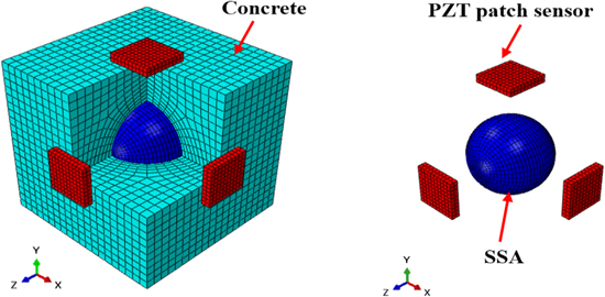
Figure 3. The finite element model of the concrete cube.
Download figure:
Standard image High-resolution imageTable 1. Material properties for the SSA and the concrete.
| Parameters | PZT-5 | Concrete |
|---|---|---|
| Density (kg m−3) | 7800 | 2400 |
| Young's modulus (GPa) | 53.2 | 24 |
| Poisson's ratio | 0.261 | 0.17 |
| Piezoelectric constant e31/e33 (C m−2) | −7.2/20.4 | — |
Elastic constant  / / / / / / (1010 N m−2) (1010 N m−2) |
10.7/5.6/5.4/8.6 | — |
Figure 4 shows the signal received by the three PZT sensors. It can be seen that the three PZT sensors received exactly the same wave response. Since the SSA model proposed in Part I is an ideal model and the distances between the SSA and each PZT patch are the same, the validity and the accuracy of the proposed SSA model can be verified.

Figure 4. Signal received by the three PZT sensors.
Download figure:
Standard image High-resolution image4. Experimental verification
4.1. Fabrication of the testing specimen
A series of tests were conducted to validate the omnidirectional actuating and sensing capabilities of the SSA. A 1 ft3 concrete specimen embedded with a SSA in the center was made in the laboratory. One SA was mounted at the center of each face of the concrete specimen using epoxy resin so that each of the SAs can generate or receive a stress wave in the corresponding face. Figure 5(a) shows the wood mold for casting the concrete specimen. A SSA sample was set in the center of the cube with the help of a supporting wood stick. The functionalities of the SSA were tested by two of the most commonly used piezo-based sensing methods, the active and passive sensing approaches. Figure 5(b) shows the experimental setup including the concrete specimen with an embedded SSA and six surface-mounted SAs, an impact hammer and a signal conditioner for the passive sensing test, and a data acquisition system (a NI-USB-6363 data acquisition board and a laptop). It should be noted that the concrete specimen was supported by four PVC caps so that the effect of the boundary conditions on the wave propagation can be minimized.

Figure 5. Concrete specimen preparation and experimental setup.
Download figure:
Standard image High-resolution image4.2. Active sensing approach
The actuating and sensing capabilities of the SSA were first verified by using the active sensing approach which includes two tests in parallel. In the first test, the SSA was used as an actuator to generate a stress wave in the concrete cube and six surface-mounted SAs were used as sensors to detect the wave response from all six faces of the concrete cube. In the second one, the SSA was utilized as a sensor to detect the wave response from each of the SAs, respectively. The experimental schematic of the two tests is given in figure 6. In this research, the excited wave generated from either the SSA or SA is a swept sine wave with the amplitude, frequency range, period of 10 V, 100 Hz to 200 kHz and 1 s, respectively.
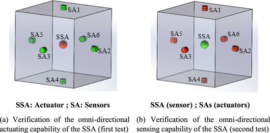
Figure 6. Experimental verification of the omnidirectional actuating and sensing capabilities of the SSA using an active sensing approach.
Download figure:
Standard image High-resolution image4.2.1. Omnidirectional actuating capability
The time-domain wave responses of the SAs when using the SSA as the actuator in the first test are shown in figure 7. Each figure gives one period of the wave response corresponding to the excitation signal. From the test results, it can be seen that all the SAs mounted on six faces can detect the wave response from the SSA, and the amplitude levels of the signals are similar. Figure 8 gives the frequency analysis of the signal responses of SAs shown in figure 7. As seen in figure 8, six curves show closed magnitude levels and a similar trend. Among the six curves, the point with the highest magnitude (SA4 at 123 kHz) is −91.8 dB and the point with the lowest magnitude (SA2 at 125 kHz) is −103.1 dB. The difference is 11.3 dB. The frequency range from which the SAs receive the maximum signal energy is 115.2 kHz (SA3) to 127 kHz (SA6). The variations among the curves are as expected due to the inhomogeneity of concrete and nonlinear wave propagating properties in a concrete structure.
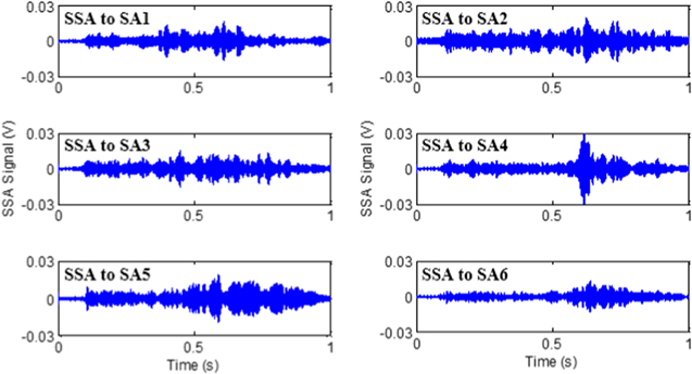
Figure 7. Wave responses of the SAs (SSA was the actuator).
Download figure:
Standard image High-resolution image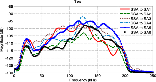
Figure 8. Frequency analysis of the SAs when SSA was used as the actuator.
Download figure:
Standard image High-resolution imageIn this test, when the SSA was used as the actuator, the omnidirectional actuating capability of the SSA can be verified. However, compared with the simulation results from which each PZT sensor receives the same wave response, the received signals in both time and frequency domains present similar amplitude levels but retain unique details. The possible reasons could be as follows: (1) the SSA was assembled by two semi-spherical hollow UHPC cases and the spherical piezoceramic shell using epoxy resin so that the SSA is not radially symmetric due to the epoxy layer; (2) the wave propagation in the concrete specimen is not uniform since concrete exhibits nonlinear properties; (3) the thickness and the geometry of the epoxy interface between the SAs and the concrete specimen differ, which may also influence the wave propagation characteristics from the SSA to SAs.
4.2.2. Omnidirectional sensing capability
The omnidirectional actuating capability of the SSA has been verified in the previous test. In the second test, the SSA was used as a sensor to detect the wave response from SAs in six individual measurements. The excited wave of each SA was the same as the one used in the previous test. Figures 9 and 10 plot the time-domain and frequency-domain signals received by the SSA according to the six individual actuators of the SAs. In the six individual measurements, the signals received by SSA present similar amplitude levels but retain unique detailed characteristics. Such an observation can be found in the time-domain signal response, and further verified by the frequency-domain analysis. The possible reasons were discussed in the previous section.
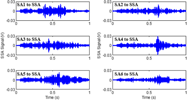
Figure 9. Wave responses of the SSA (SSA was the sensor).
Download figure:
Standard image High-resolution image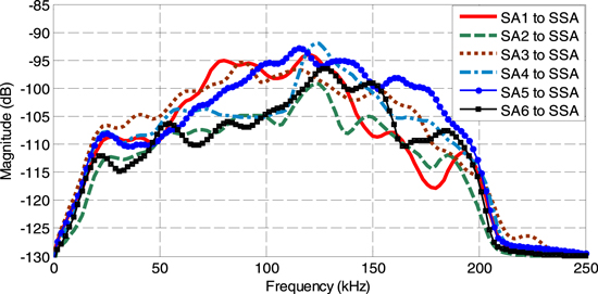
Figure 10. Frequency analysis of the SSA when each SA was used as an independent actuator.
Download figure:
Standard image High-resolution image4.3. Passive sensing approach
Both the actuating and sensing capabilities of the SSA were validated in the active sensing approach. The passive sensing approach is another important sensing technology. In this section the performance of the SSA in the detection of the impact events is investigated. The experimental schematics are shown in figure 11. Three tests were conducted to generate impact events from three different faces by using a piezo-based impact hammer. Each test includes five individual impact events. The signals from both the impact hammer and the SSA were collected.
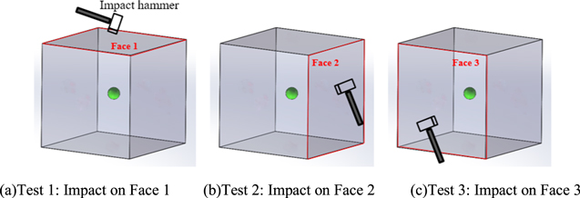
Figure 11. Experimental schematics of the passive sensing approach.
Download figure:
Standard image High-resolution imageFigure 12 shows the signal of both the impact hammer and the SSA from the three tests. It can be seen that the SSA is capable of detecting the impacts from different directions. Therefore, the omnidirectional sensing capability of the SSA can be verified. The peak ratios between the signal of the SSA and the signal from the impact hammer were calculated and are presented in figure 13. Based on equation (4), the value of the peak ratios should be the same since the distance between the impact location and the SSA is the same for all three tests. However, the peak ratios from the experiments vary around 1. The possible reasons are the non-symmetrical properties of the SSA due to the epoxy layer and the nonlinear properties of the concrete material. It should be noted that distributive SSAs have to be deployed in the concrete to further detect the location of the impact [19].
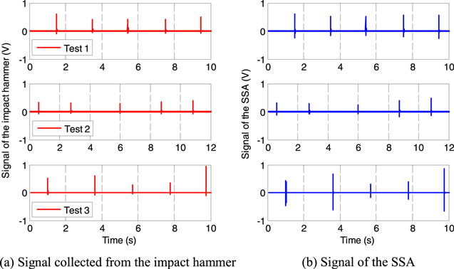
Figure 12. Signals from the impact hammer and the SSA.
Download figure:
Standard image High-resolution image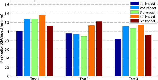
Figure 13. Peak ratios (SSA/impact hammer) calculated from the impact tests.
Download figure:
Standard image High-resolution image
4.4. Discussions
In this research, the omnidirectional actuating and sensing abilities of the SSA were verified. The proposed SSA will significantly improve the detection aperture compared with the current SA-based SHM system. In many cases, if the location of the damage or impacts is unpredictable, the SSA can replace the typical deployment of SA sensing networks. Due to the high strength of the UHPC protection and the similar shape of the SSA to a normal aggregate used in concrete, the embedded SSA should have very limited effects on the overall strength of the concrete structure. In the current stage, though the numerical results exhibit the perfect radially symmetrical actuating properties of the SSA, the expected results can hardly be achieved in the experiments due to the nonlinear properties of the concrete material and the influence of the epoxy layer for SSA assembly. For real applications using SSA for SHM a baseline date is required to overcome the influence of the nonlinear properties of the concrete material on the wave propagation. In addition, the design of the SSA still need to be improved to minimize the non-symmetrical effects of the SSA.
5. Conclusions
In the second part of the paper, the functionality of the SSA was verified in both numerical simulations and experiments. In the numerical study, the accuracy of the proposed SSA finite element modal was verified using the active sensing approach. In the experimental study, the performance of the SSA in both the active sensing approach and passive sensing approach was investigated. Due to the nonlinear properties of the concrete material and the epoxy layer of the SSA, the radially symmetrical actuating and sensing capability of the SSA is still limited. However, the effects of the non-symmetrical properties of the SSA will be minimized when considering them as the baseline data for SHM. The performance of the SSA for different applications of structural health monitoring will be investigated in future work. In addition, the relationship between the constitutive equations of the SSA and the determination of the impact force will be theoretically and experimentally studied.