
Abstract
The nitride layer formed in the target race track during the deposition of stoichiometric TiN thin films is a factor 2.5 thicker for high power impulse magnetron sputtering (HIPIMS), compared to conventional dc processing (DCMS). The phenomenon is explained using x-ray photoelectron spectroscopy analysis of the as-operated Ti target surface chemistry supported by sputter depth profiles, dynamic Monte Carlo simulations employing the TRIDYN code, and plasma chemical investigations by ion mass spectrometry. The target chemistry and the thickness of the nitride layer are found to be determined by the implantation of nitrogen ions, predominantly N+ and  for HIPIMS and DCMS, respectively. Knowledge of this method-inherent difference enables robust processing of high quality functional coatings.
Export citation and abstract BibTeX RIS

Content from this work may be used under the terms of the Creative Commons Attribution 3.0 licence. Any further distribution of this work must maintain attribution to the author(s) and the title of the work, journal citation and DOI.
Advanced functional coatings with applications ranging from wear-resistant layers on cutting tools [1, 2] to diffusion barriers in electronic devices [3, 4] are often produced with the advantage of reactive magnetron sputtering under high vacuum conditions. The presence of a reactive gas, however, leads not only to the desired compound formation at the substrate, but also to a simultaneous chemisorption at the target that is covered with a compound layer by so-called target poisoning. This results in severe reduction of the sputtering rate and large off-sets in the process parameter operating points, because of the change in the secondary electron emission yield and the chemical composition of the sputtered flux, as well as the energy distribution thereof, [5, 6] ion implantation effects, [7] and process hysteresis [8].
As the latest development in the field of magnetron sputtering, high power impulse magnetron sputtering (HIPIMS) [9] is mostly known for the ability to provide significant ionization of the sputtered material flux [10–14]. In contrast to conventional dc magnetron sputtering (DCMS), where the target state in the reactive process is to a large extent determined by the applied power and the supply of the reactive gas, HIPIMS offers an additional means of control by tuning the pulse length and pulsing frequency, which can potentially lead to new phenomena at the target surface. For example, it was reported recently that a ~500 nm thick compound layer formed on a Ti target surface operated in an oxygen-containing atmosphere by HIPIMS [15], while the typical thickness of the reacted film during DCMS is only a few nm [16, 17].
Experimental studies of the target surface chemistry [18, 19] have been limited by a lack of in situ analytical probes capable of operating under the harsh plasma process conditions used for film growth. An additional snag is that x-ray photoelectron spectroscopy (XPS), used for bonding assignments of magnetron sputtered thin films, is typically performed ex situ, which implies complications arising from the sample oxidation during transport to the spectrometer. Commonly used surface cleaning by Ar+-ion etching is not a remedy, as it has other destructive effects [20]4, like preferential sputtering, surface roughening, and redeposition of sputtered materials.
Here, we compare the chemical state of a Ti target operating in Ar/N2 atmospheres using DCMS and HIPIMS, with gas composition optimized to yield stoichiometric TiN films at the substrate. The targets are in situ capped immediately after each film deposition experiment with a few-nm-thick photoelectron-transparent metal-protective layers [21] and subsequently transferred from the growth chamber into the XPS instrument. This new method enables ex situ studies of native target chemistry [22, 23]. High-energy resolution core-level photoelectron spectra recorded from native surfaces, together with sputter-depth profiles reveal essential differences between the two sputtering techniques. HIPIMS operation results in a factor of 2.5× thicker nitride layer than in the case of conventional DCMS, despite the lower N2 partial pressure  used. Even if operated at
  , too low to result in stoichiometric TiN films on the substrate, the target surface region is fully nitrided during HIPIMS, which is in clear contrast to DCMS [24].
Experiments are conducted in a multi-cathode CC800/9 CemeCon AG magnetron sputtering system [25], employing a rectangular 8.8 × 50 cm2 Ti target. A 2 × 4 cm2 section of the target, positioned in the middle and across the race track, is made to be detachable to allow for transfer to the XPS system. The background pressure prior to sputtering is 0.2 mPa (1.5 × 10⁻⁶ Torr). The total pressure of Ar/N2 gas mixture is kept constant at 0.4 Pa (3 mTorr), with  set at 92 mPa for DCMS experiments, while
  = 45 mPa for HIPIMS. In both cases,
  is the lowest N2 partial pressure to yield stoichiometric TiN films at the substrate. DCMS is operated at a 2 kW average power, resulting in a target voltage of −351 V. The same target power is used for HIPIMS, together with the 200 µs pulse width and the frequency of 200 Hz. Such experimental conditions result in the incorporation of oxygen from the residual gas [26] causing a bulk oxygen content in the DCMS and HIPIMS films of 0.2 and 0.9 at%, respectively, as assessed by time-of-flight elastic recoil detection analysis. Prior to each experiment, the target is conditioned for 5 min in pure Ar behind closed shutters to reset the target history5. For each gas mixture studied, the target is operated for 10 min to assure steady-state conditions.
To prevent target surface oxidation by atmosphere exposure during transport to the XPS instrument [27], Al-caps are deposited following the sputtering tests. First, the Al target, intended for cap layer deposition, is sputter-cleaned in Ar for 120 s at 2 kW behind closed shutters. We do not expect any chemical reactions on the target side during this time, as previous studies indicate that the post-deposition exposure of freshly-grown films to residual gases, including oxygen and water vapor, does not significantly affect the surface chemistry [27]. After that, the Al target power is reduced to 0.4 kW and a capping overlayer is deposited on the Ti target with a thickness of 50 ± 5 Å, as estimated from the attenuation of core level signals [28]. Subsequently, the detachable Ti target fragment is transferred to the load-lock chamber of the UHV XPS system. The total air exposure time is shorter than 2 min.
XPS is performed in an Axis Ultra DLD instrument from Kratos Analytical (UK) employing a monochromatic Al Kα source (hν = 1486.6 eV). The base pressure during spectra acquisition is better than 1.5 × 10⁻⁷ Pa (1.1 × 10⁻⁹ Torr). All spectra are collected at a normal emission angle from a 0.3 × 0.7 mm2 area centered in the middle of the target race track. The BE scale is calibrated against the Fermi level cut-off [29]6, using the procedure described in detail elsewhere [23] in order to avoid BE referencing problems resulting from the fact that C 1s BE depends on the type of surface oxides formed during the venting procedure [27], and to remove ambiguities related to the use of C 1s as the BE [30]. For depth profile experiments, Ar+ ions with an energy of 0.5 keV incident at a 70° angle from the surface normal are used to clean a 3 × 3 mm2 area in the middle of the race track. The sputter rate is calibrated by etching through a 300 nm thick TiN film grown on Si(0 0 1) substrates.
Figure 1 shows voltage and current waveforms recorded during HIPIMS of Ti target, which are used below to derive the energy-averaged nitrogen implantation profile. The target voltage is −700 V at t = 0 µs and decreases rapidly with time, due to the size of the capacitor bank with respect to the target area, to reach −140 V with t = 70 µs. After plasma ignition at t = 5 µs, the target current increases to a maximum value 1280 A at 32 µs and decays to zero within the next ~45 µs.

Figure 1. Target voltage and target current waveforms recorded during HIPIMS of Ti target in Ar/N2 mixture with N2 partial pressure of 45 mPa.
Download figure:
Standard image High-resolution imageNormalized Ti 2p spectra recorded from Al-capped Ti targets after sputtering in (i) DCMS mode with  = 92 mPa, and (ii) HIPIMS mode with
  = 45 mPa are shown in figure 2. In both cases,
  is adjusted to grow stoichiometric TiN films. In addition, the Ti 2p spectrum obtained from a polycrystalline TiN thin film surface, deposited in the HIPIMS mode with the exact same settings as specified above, and previously sputter-etched with 0.5 keV Ar+ ions, is included for reference. There is a very clear difference in the appearance of Ti 2p spectra depending on whether the target was operated in DCMS or in HIPIMS. In the former case, the Ti 2p spectra possess two distinct contributions, with stronger 2p3/2 spin-split components at 454.0 and 455.0 eV, corresponding to Ti and TiN, respectively [31]. The relative signal variation revealed by the angle-dependent XPS (not shown) indicated a layer-over-layer structure. The thickness of the top nitride layer was estimated to be 29 Å [22], based on the relative peak intensities of metal and nitride components in the fitted Ti 2p XPS spectra supported by TRIDYN simulations [32, 33].
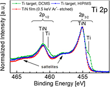
Figure 2. Ti 2p XPS spectra obtained from Al-capped Ti target operated with DCMS at  = 92 mPa, as well as, with HIPIMS at
  = 45 mPa. N2 partial pressures are optimized to yield stoichiometric films at the substrate. Included for the reference is the Ti 2p spectrum from TiN thin film sputter-cleaned with 0.5 keV Ar+ ions incident at 70° from the surface normal. Satellite peaks on the high BE side of the primary signals are commonly observed, however, beyond the scope of this paper.
Download figure:
Standard image High-resolution imageIn contrast to the DCMS case, the Ti 2p spectrum acquired after HIPIMS operation exhibits only one 2p3/2 peak, assigned to TiN. The lack of a metallic contribution is direct evidence for a thicker surface TiN layer than during DCMS, clearly exceeding 54 Å, which is the estimated XPS probing depth7. The overall spectral envelope is essentially identical to that from the sputter-etched TiN-film reference. The agreement is exceptionally good, given that the Ti 2p spectrum of TiN is prone to exhibit the destructive effects of an Ar+ ion etch [21]. This can be rationalized by the fact that, in both cases, for the target sputtered in Ar/N2 atmosphere, as well as the Ar+-etched TiN film, the surface is exposed to Ar+ ions with similar energy. Good agreement also indicates that the potential influence of a higher surface roughness of the Ti target on the quality of the XPS spectra is negligibly small.
To verify the estimates of compound layer thickness based on Al-capped samples, we performed sputter depth profiles on Ti targets after (a) DCMS and (b) HIPIMS operation. Figure 3 shows the Ti 2p3/2 spectra evolution as a function of sputtering depth. The starting point denoted as '0 Å' corresponds to the sample state after removing the Al capping layer. In the case of the target operated under DCMS conditions, the Ti 2p3/2 spectrum changes rapidly with increasing depth. The TiN component at 455.0 eV decreases, while the metallic peak at 454.0 eV increases in intensity, such that after first removing12 Å, both contributions are approximately equal. However, the steady state is not reached until the top 28–32 Å are removed and the spectrum contains one metallic peak at 454.0 eV with an asymmetric tail on the high BE side characteristic of a metallic Ti [34]. Hence, there is a very good agreement between the present result and the nitride thickness of 29 Å, estimated above from the Ti 2p spectrum of the Al-capped Ti target.

Figure 3. Ti 2p3/2 XPS depth profiles obtained from Ti target surface after (a) DCMS at  = 92 mPa, and (b) HIPIMS at
  = 45 mPa. N2 partial pressures are optimized to yield stoichiometric films at the substrate.
Download figure:
Standard image High-resolution imageThe corresponding depth profile performed under the exact same conditions on the target previously operated in HIPIMS fully confirms that a much thicker compound layer is formed (see figure 3(b)). First, after removing 12 Å, which in the case of the DCMS target results in a Ti 2p3/2 spectrum with equal Ti and TiN peak intensities, the core level signal from the HIPIMS target is still completely dominated by the TiN contribution, with only a small indication of a metallic peak at 454.0 eV. It is not until the 36 Å material is removed that both the Ti and TiN peaks become equally intense. Interestingly, the gradual change between two consecutive spectra is significantly smaller in the case of a HIPIMS-exposed target, indicative of a more diffuse nitride/metal interface than observed for a DCMS target, which likely results from the fact that the amplitude of the target voltage (hence, incident ion energy) varies in a wide range during the HIPIMS pulse (see figure 1). The steady-state condition, corresponding to the metallic Ti spectrum, is reached at the depth of 72–76 Å, which is ~2.5 times deeper than for the DCMS target. Thus, at the reactive gas partial pressures that ensure stoichiometric film growth at the substrate, compound layer formation is more efficient during HIPIMS as compared to DC processing.
To explain the observed differences between the surface composition of Ti targets operated in DCMS and HIPIMS, we performed dynamic Monte Carlo collisional computer simulations using the TRIDYN code [35, 36] of the stationary nitrogen depth profiles. During DCMS with Ar/N2 gas mixtures optimized to obtain stoichiometric films, the majority of the ion species incident at the growing film are Ar+,  , and N+, with the
  /N+ ratio increasing with increasing
  [37].
[37].
Our previously reported in situ ion mass spectrometry measurements of Ti-DCMS plasma with  = 80 mPa showed that
  population is ~50 times higher than N+ [38], thus, in the TRIDYN simulations of DCMS operation, the latter species can be neglected. The first approximation to the
  ion content in the plasma (relative to that of Ar+) can be obtained from the N2/Ar partial pressure ratio, since under DCMS conditions, both gases have similar electron impact ionization cross sections [39], while the ionization potentials are very similar [40]. The cathode sheaths are collision-less, thus, with the plasma potential not higher than a few volts, the incident ion energy can be approximated by the target voltage [41], given that the voltage drop in the magnetic sheath is minor [42]. Therefore, in simulations, we use 350 eV Ar+, while each
  ion, first neutralized by electron pickup from the target, dissociates upon impact and the incident energy splits equally between the two N atoms. The steady-state conditions require 2 × 10⁵ pseudoparticles, representing the total fluence of 5 × 10¹⁷ ions/cm2. The simulated profile indicates close-to-stoichiometric TiNx with x = 0.94, which forms a relatively sharp interface to metallic Ti at 32 ± 2 Å, in excellent agreement with XPS estimates from Al-capped samples (29 Å) and the results of sputter depth profile (28–32 Å).
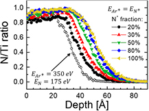
The TRIDYN simulations in the case of HIPIMS are more complex since the energy of incident ions is not constant, due to the target voltage VT varying during the pulse (see figure 1). To handle this effect, we performed TRIDYN for an applicable range of incident ion energies from 100 to 700 eV, in steps of 100 eV. As the ion flux to the target is proportional to the target current, the I–V plot can be considered a first-order approximation to the ion energy distribution function, which can in turn be used to derive the energy-averaged N implantation profile based on TRIDYN results obtained for specific ion energies.
In the first case, similar to DCMS, we assumed Ar+ ( = 350 eV) and
  ions that dissociate upon impact and give rise to two N atoms, each with
  = 175 eV. As shown in figure 4, the results indicated that the N implantation depths are too short to explain the XPS data. Essentially, no N is found deeper than ~45 Å, which is inconsistent with the XPS findings (see figure 3(b)).
Figure 4. The energy-averaged N implantation profiles based on TRIDYN results obtained for specific ion energies assuming: (open circles)  350 eV together with
  175 eV, and (filled circles)
  . In the latter case, results are shown as a function of N+ fraction in the ion flux incident on the Ti target.
Download figure:
Standard image High-resolution image
Importantly, previous ion mass spectrometry measurements, conducted during Ti HIPIMS in Ar/N2 atmosphere in the same deposition system as used for the present experiments, revealed that gas ion fluxes at the substrate are dominated by N+ rather than  , with Ar+,
  , and N+ contributions amounting to 36, 17, and 47%, respectively [38]. This is also consistent with other reports on reactive HIPIMS of transition metal targets [43, 44]. Therefore, in the following simulations we assumed that the population of reactive gas ions during HIPIMS is dominated by N+ implying
  . Figure 4 shows the calculated N/Ti implantation profiles for a N+ fraction in the Ar+/N+ flux incident on the Ti target varying between 20 and 100%. The lower limit corresponds to the N/Ar atom ratio for the N2 partial pressure of 45 mPa. Interestingly, the minimum N+ fraction necessary to explain the XPS results is 50%, which corresponds very well to the relative N+ population during HIPIMS discharge analyzed in [40]. The source of N+ can be (a) electron-impact induced dissociation of N2, and (b) N sputtered from the poisoned target surface. An additional effect, which may further increase the N+/Ar+ ratio in the ion flux incident on the Ti target is Ar rarefaction [45]. With a better mass match to Ti atoms, resulting in a more effective momentum transfer, Ar is diluted more than N2 and N.
To complement the above results, we also analyzed the HIPIMS target chemistry for  lower than 45 mPa. The N/Ti ratio, as determined by the XPS (not shown), hence reflecting the average N and Ti concentrations within the 54 Å thick surface layer [28], was at 0.98 and 0.88 for
  = 27 and 9 mPa, respectively. Thus, in the HIPIMS mode, the Ti target surface region remained severely nitrided, while corresponding films were understoichiometric in nitrogen.
In summary, during the deposition of stoichiometric TiN thin films by HIPIMS, the formation of a 2.5× thicker nitride layer in the center of the race track was observed, as compared to conventional dc processing. The ~50 Å thick target surface region is nitrided during HIPIMS, even at  values too low to yield stoichiometric TiN films on the substrate, which is in clear contrast to conventional DCMS. The differences between the nitride layer thickness during reactive DCMS and HIPIMS can be understood based on correlative plasma chemical investigations and TRIDYN simulations. N+ ions that dominate nitrogen ion flux during HIPIMS arrive at the target with significantly higher energy than molecular
  present in DCMS discharge, resulting in much longer implantation depths. Based on the excellent agreement between TRIDYN simulations and XPS analyses, we conclude that the formation of the compound layer is entirely caused by the implantation of nitrogen ions.
Acknowledgments
The authors want to thank Dr. Andre Anders for helpful discussions. The authors gratefully acknowledge the financial support of the German Research Foundation (DFG) within SFB-TR 87, the Knut and Alice Wallenberg Foundation Scholar Grant KAW2016.0358, the VINN Excellence Center Functional Nanoscale Materials (FunMat-2) Grant 2016-05156, the Åforsk Foundation Grant 16-359, and Carl Tryggers Stiftelse contracts CTS 15:219 and CTS 14:431.
Footnotes
- 4
For more detailed treatment see, e.g. [20] and references therein.
- 5
It was established in a control experiment that the sputtering rate from the Ti target is not lower than 54 nm min−1 × kW. Hence, we estimate that the target cleaning procedure applied in this work results in removing the surface layer which is about 2 orders of magnitude thicker than the compound layer formed during reactive operation.
- 6
See for instance chapter 1 in [29].
- 7
The probing depth is defined as the surface layer that yields 95% of the signal intensity, and is equal to 3 × λ, in which λ stands for the inelastic electron mean free path for Ti 2p electrons excited with Al Kα radiation and penetrating through Ti. Values of λ are taken from [28].