
Abstract
Lithium-ion batteries (LIBs) are the energy storage devices that dominate the portable electronic market. They are now also considered and used for electric vehicles and are foreseen to enable the smart grid. Preparing batteries with high energy and power densities, elevated cycleability and improved safety could be achieved by controlling the microstructure of the electrode materials and the interaction they have with the electrolyte over the working potential window. Selecting appropriate precursors, reducing the preparation steps and selecting more efficient synthesis methods could also significantly reduce the costs of LIB components. Implementing plasma technologies can represent a high capital investment, but the versatility of the technologies allows the preparation of powdered nanoparticles with different morphologies, as well as with carbon and metal oxide coatings. Plasma technologies can also enable the preparation of binder-free thin films and coatings for LIB electrodes, and the treatment of polymeric membranes to be used as separators. This review paper aims at highlighting the different thermal and non-thermal plasma technologies recently used to synthesize coated and non-coated active materials for LIB cathodes and anodes, and to modify the surface of separators.
Export citation and abstract BibTeX RIS
1. Introduction
Today, the world faces the imperative need of decreasing its consumption of fossil fuels that are limited resources and that lead to environmental pollution. To address this problematic, many research groups put an immense effort in developing new and/or better technologies that fulfill the requirements of powering electronic devices and large scale applications like electric vehicles. In this sense, Li-ion batteries (LIB) have succeeded as energy storage devices owing to the versatility of their chemistry, which allows for an efficient conversion of chemical energy into electrical energy [1, 2]. Since 1991, when Sony Corporation first commercialized rechargeable lithium-ion batteries, these batteries have been largely used as power sources in portable electronics and are now the system of choice to power electric vehicles and to integrate energy storage capabilities in the grid. However, in order to satisfy these energy storage demands, LIBs are required to be improved in terms of energy density, power density, cycleability, safety and cost.
A battery is an electrochemical device constituted by several electrochemical cells connected either in series or in parallel. Such electrochemical cells consist of a positive and a negative electrode that are connected to an external circuit through which electrons flow. The electrodes are separated by an electrolyte, which is an electronic insulator but an ionic conductor, and a separator (e.g. polymeric membrane) that prevents physical contact between the electrodes [1, 2]. The chemical reactions that generate electricity take place at the two electrodes, where each of them undergoes a half-cell reaction, where the driving force for these reactions is the difference in the electrode potentials. During a discharge, the negative electrode is oxidized and provides electrons to the external circuit through the current collector, while the positive electrode accepts these electrons and participates in the complementary reduction reaction. Meanwhile, the electroneutrality of the electrodes is maintained by the flow of cations contained in the electrolyte (e.g. Li+) from the negative to the positive electrode. A schematic view of a Li-ion cell, showing ideal electrode materials where A+ ions are located in inter-lattice positions that favors ions diffusion, is depicted in figure 1. Charge and discharge rates are commonly referred to as C or C-rates. The 1 C rate dictates (from an ideal calculation) the current required to discharge the nominal capacity of the battery in 1 h.
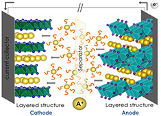
Figure 1. Schematic view of an alkali-ion battery on discharge mode. The cathode and anode are shown together with the alkali ions (yellow), the electrolyte (orange) and the separator.
Download figure:
Standard image High-resolution imageResearch on Li-containing materials has largely focused on intercalation compounds, where electrode materials having 2D or 3D crystal lattice serve as host structures to Li+ guest ions that can be inserted/extracted without suffering structural changes. Among the many compounds investigated to be used as positive electrode materials, lithium transition metal oxides (V, Mn, Fe, Co, Ni) and polyanionic frameworks (e.g. phosphates) have caught the biggest attention. For example, layered oxide LiCoO2, with a theoretical capacity of 274 mAhg−1, is the cathode material used in most portable devices. Olivine LiFePO4, with a theoretical capacity of 170 mAhg−1, is also commercially available. In the case of negative electrodes, Li metal was initially proposed as counter electrode; however, safety concerns regarding dendrite formation upon electrochemical cycling pointed to the investigation of new negative electrode materials such as carbon-based materials. Today, negative electrodes include carbonaceous materials (graphite, ungraphitized soft carbon and hard carbon), titanates (Li4Ti5O12, TiO2), transition metal oxides and alloys containing Si or Sn [3–9].
Although LIBs are vastly dominating the electronic market, some disadvantages could compromise their widespread adoption in other fields: safety concerns due to the use of volatile electrolytes, aging effects, limited performance at high temperature and elevated cost. Also, the high production cost of LIBs is mainly explained by an uneven distribution of Li in Earth's crust and dried salt lakes, and by geopolitical constraints that could compromise the accessibility to the raw materials (minerals and salts). In addition, an important fraction of the expenses are related to the preparation and processing procedures of electrodes, given the series of time-consuming steps, various solvents and controlled environment required to obtain crystallized and purified active materials (e.g. synthesis of LiFePO4). For example, solid-state reactions are carried in sealed containers at high temperatures and, generally, initial and intermediate grindings of both precursors and products are needed. Synthesis routes in liquid media, like the hydro/solvothermal method, provide a wide range of options including temperature, pressure, solvents and precursors. This method usually entails a single-step synthetic procedure and enables the preparation of samples with well-defined chemistry, size and morphology for specific applications. However, large amounts of solvents are used and washing steps are added to achieve a pure sample. Sol-gel methods are also performed in several steps that include dissolving the precursors in a solvent, promoting the formation of the sol-gel by adding monomers, heating the solution, calcining the gel and annealing the final product. Another procedure that is increasingly implemented in the preparation of inorganic compounds is the mechanochemical synthesis. This method is often solvent-free and requires successive grinding/milling processes. Its main drawback is the difficulty in achieving pure phases.
The above-mentioned synthetic methods for the preparation of electrode materials are compared in table 1, together with plasma technologies. Nowadays, the research is mainly focused in the preparation of nanostructured materials for LIB with controlled size and morphology in order to obtain superior electrochemical performance. The use of nanosized electrode materials provide key advantages: the electrode/electrolyte contact area is increased and so are the charge-discharge rates, and the shorter Li+ diffusion path lengths promote ion transport with low polarization [10]. Customization of the morphology of particles could also mitigate the volumetric changes of the electrodes upon cycling, as reported for the hollow-spherical CuO electrodes [11, 12]. Preferred orientation growth of particles also influence the diffusion path of ions, as exemplified for the layered cathode materials where the {0 1 1 0} facets present an open surface structure exposing the Li+ diffusion channels and facilitating the ion migration of Li+ between the MO6 octahedra interlayers. LiNi1/3Co1/3Mn1/3O2 (NCM) was synthesized with ~60% of {0 1 1 0} facets and showed an excellent initial discharge capacity of 159 mAhg−1 at 2 C and 89% charge retention after 100 cycles, while bulk NCM obtained by solid-state reaction showed an initial discharge capacity of ~118 mAhg−1 at 2 C and a large capacity fading (50%) [13, 14].
Table 1. Comparison of synthetic methods used to produce electrode materials for LIB.
| Synthesis method | Process | Limitation | Cost |
|---|---|---|---|
| Coprecipitation | Preparation of powder through precipitation in aqueous solution. | Irregular morphology | Low |
| Impurities | |||
| Crystallization in liquids | |||
| Solid-state | Synthesis under controlled environment at high temperature. | High aggregation | Low |
| Irregular morphology | |||
| Grinding steps | |||
| Solvothermal | Precursors dissolved or dispersed in solvents. Product obtained at controlled temperature and pressure. | Batch synthesis | Medium-high |
| Use of solvents | |||
| Wide particle size distribution | |||
| Ball-milling assisted solid-state | Combination of precursor in a stainless steel or zirconia vessel. High energy ball milling followed by sintering. | Agglomeration | Medium |
| Impurities | |||
| Low crystallinity | |||
| Sol-gel | Several steps that include solvent mixing, heating, calcination, grinding, sintering. | Several steps | Medium |
| Limited to metal oxides | |||
| Non-thermal plasma | Non-equilibrium plasma source with high electronic temperature triggering chemical reactions in gases. | Vacuum | Medium-high |
| Low production rate | |||
| Thermal plasma | High density, high enthalpy plasma source used to melt/vaporize various precursors (solid, liquid or gases). Nucleation of nanoparticles in the quench zone, collected in filters or deposited as coatings. | Thermophoresis | High |
| Agglomeration | |||
| Impurities | |||
| No selectivity |
Plasma-based procedures have been proposed to synthesize or to modify electrode materials and separators, with controlled nanoparticle composition, size and morphology, starting from various precursors and using very few steps. This review covers the most recent implementations of plasma processing technologies in the LIB field, highlighting the potential of plasmas for large scale production and modification of LIB electrode materials and separators.
2. Plasma technologies
2.1. Interesting features of plasma technologies.
Most man-made plasmas consist of a partially ionized gas containing freely and randomly moving charged (electrons and ions) and neutral particles. Plasmas are often classified as a function of electron density and electron temperature. Those of practical interests for the synthesis and modification of lithium-ion battery materials have an electron density in the range  cm−3 and an electron temperature of
  eV. Such temperatures are much higher than those achievable by ordinary chemical means. It is also convenient to make a distinction between thermal and non-thermal plasmas. A thermal plasma is in kinetic equilibrium and meets all the requirement for local thermodynamic equilibrium (LTE): the temperature of heavy particles
  approaches that of electrons
  , the plasma is in chemical equilibrium, and other restrictions on gradients also apply. When
  , the plasma is termed non-equilibrium or non-thermal plasma.
With a temperature in the  eV range, a large fraction of electrons have enough energy to form reactive species (atoms, ions and free radicals) from various gaseous feedstocks. Thermal plasmas are usually seen as more energetic, indiscriminately forming several reactive species even from liquid and solid feedstocks, whereas non-thermal plasmas are much more chemically selective. A large number of plasma-based processes have been developed to synthesize or to modify materials for applications in microelectronics, inorganic nanoparticles and carbonaceous compounds synthesis (e.g. graphene, carbon nanotubes), thermal barrier, wear-resistant and corrosion-resistant coatings, solid oxide fuel cells and other energy conversions systems. Plasma sources generally offer advantages in terms of large processing scales (nanomaterials can be produced in kg/h and thin films and coatings can be deposited over large areas) and in terms of environmental impacts (plasmas are generated from electrical energy and eliminate/reduce the usage of toxic solvents).
In particular, several research groups have studied the synthesis of nanoparticles in thermal and non-thermal plasmas [15–33]. Recently, a Special issue on 'Plasma synthesis of nanoparticles' [34] was also published by J. Phys. D: Appl. Phys. Although most of them may not have directly targeted Li-ion battery applications, their pioneering work must be recognized and is highly valuable to foster the development of plasma technologies for Li-ion batteries, especially for silicon-based anodes [15, 16, 18–21, 23, 25, 28, 29, 32].
Non-thermal plasmas have been largely used for the synthesis of semiconductor nanocrystals, metal nanoparticles and for surface chemistry. Their main attributes for the synthesis of nanoparticles rely on an electronic temperature that is much higher than that of the heavy ions and neutrals (the collision rate between electrons and heavy particles is insufficient for gas thermalization). As such, non-thermal plasmas enable the synthesis (i) of products with high purity and controlled size distribution, (ii) of high melting point material in crystalline form and (iii) of negatively charged nanoparticles avoiding agglomeration, all processes driven far from chemical equilibrium and at low temperature by energetic electrons [26]. Most non-thermal plasmas are formed under vacuum (<1 Torr) to facilitate ionization, which calls for expensive equipment and high operating costs. This drawback has driven the development of atmospheric pressure plasma processes for the synthesis of nanomaterials. Non-thermal atmospheric pressure plasmas offer non-equilibrium chemical reaction paths, high radical densities and multiphase plasma-liquid processing capabilities [30]. However, the increase in pressure triggers undesirable phenomena within the plasma: gas thermalization, limiting the choice of processed materials and/or substrate, and discharge instabilities, which may affect the quality and uniformity of the products [30]. An effective way to deal with these undesirable phenomena is to use microplasma sources, which confine the plasma discharge to dimensions inferior to 1 mm in at least one direction [35]. Continuous-flow and microreactor geometries reduce the residence time of nanoparticles, limit aggregation, make nanoparticle collection easier and result in highly uniform nanoparticle size distributions [35]. However, the production rate of non-thermal plasmas and microplasmas (even when arranged in large (e.g.  ) 2D arrays) in particular, is very limited (see figure 2). Considering that the active materials (anode and cathode) accounts for roughly 40% of the weight of a Li-ion battery, and that a hybrid electric vehicle battery pack weights 20 kg (a number that goes above 450 kg for an electric vehicle) [36], one sees that the throughput of non-thermal plasmas is incompatible with both hybrid and electric vehicle requirements.
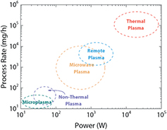
Figure 2. Typical gas-phase plasma processing rates for the synthesis of silicon nanoparticles. Reprinted from [21], © 2015, with permission of John Wiley and Sons.
Download figure:
Standard image High-resolution imageAs seen in figure 2, increasing the process rate of nanomaterials to kg h−1 requires thermal plasmas. The high production/deposition rate of thermal plasma processes results from the high density of a high power discharge at or close to atmospheric pressure. Nanoparticles, films and coatings can be synthesized, even for materials with a high melting point [24, 37, 38]. Still, this comes with drawbacks such as contamination from melted or vaporized electrode and reactor components, loss of nanoparticles due to thermophoresis, and more agglomeration as a result of a lower electron temperature, which reduce the nanoparticle charges [26].
Both thermal and non-thermal plasmas have been proven useful to synthesize or to modify lithium-ion battery cathodes, anodes and separators. The major plasma sources used for that purpose will now be briefly reviewed (for more details, see [39–42]), followed by a more exhaustive presentation of the LIB materials produced or modified with plasma technologies.
2.2. Thermal plasmas
Thermal plasma technologies are mainly used to synthesize nanomaterials [24, 37, 38], including core-shell particles, or to deposit (spray) thick coatings [40]. As such, they can address several issues associated with the electrochemical performance of LIB electrode materials: minimizing the particle size to improve the Li+ intercalation/deintercalation process, adding carbon to the active material and eliminating the binder. Moreover, plasma spraying of suspensions (SPS) or precursors in solution (SPPS) enables a precise control of the chemistry of the materials to be deposited, an asset in developing partially substituted anode and cathode materials.
2.2.1. Inductively coupled plasma torch.
In a radio frequency (RF) inductively coupled plasma (ICP) torch, the plasma is generated by coupling the electromagnetic field induced by a coil into the cylindrical discharge cavity. RF-ICP plasmas are characterized by the absence of electrodes and can be operated under inert, oxidizing, reducing or other reactive atmospheres. Soft vacuum conditions usually prevail ( kPa). Pure Ar or Ar-containing mixtures are generally used as central gases (Ar being easily ionized), while reactive gases, if any, are injected into the sheath stream. The LTE plasma temperature can reach
  K, while the plasma velocity remains under
  m s−1, unless a de Laval nozzle is used (in which case the flow can reach supersonic velocities). One of the largest applications of RF-ICP torches is the synthesis of nanomaterials with high purity (the electrodeless plasma generation reduces the risks of contamination) and with controlled chemistry and morphology [24].
Two sequences of physical and/or chemical processes can occur within the plasma and lead to the formation of nanoparticles: evaporation-condensation and evaporation-reaction-condensation [24]. Feedstocks (powders, suspensions, solutions, catalysts and/or gases) are injected axially into the plasma discharge cavity, heated in flight, melted and vaporized. Depending on the nature of the resulting vapors and injected gases, one or more species can react in-flight within the plasma jet. Then, a rapid quenching of the vapor cloud inside a cylindrical reactor (figure 3) results in condensation and nucleation of nanoparticles, which size, morphology and composition (e.g. nanospheres, nanowires, nanotubes, nanoplatelets, pure metals, oxides, carbides, etc) will depend on the quenching conditions [43]. For example, long isotherms in a reducing atmosphere are suitable for the growth of carbon nanotubes [44], while a rapid quench in an oxidizing atmosphere can lead to small particles having polyhedral shapes [45]. Generally, smaller particles are obtained by limiting their recirculation within the quench zone [43, 46]. The nanoparticles are collected onto the reactor walls or onto a downstream porous filter. Reactive gases can be used to modify or to functionalize the particles in flight, as demonstrated with carbon nanotubes in the presence of NH3 downstream of the growth zone [47]. This is an interesting feature for LIB materials. ICP torches can also be used to spray coatings under controlled atmospheres (figure 3).
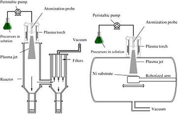
Figure 3. Schematic view of the inductively coupled thermal plasma reactor used for the synthesis of nanomaterials (left) and deposition of coatings (right). Reprinted from [48], © 2015, with permission of Springer.
Download figure:
Standard image High-resolution image2.2.2. Direct current plasma torch.
Direct current (DC) plasma torches generate plasma by striking an arc between the cathode and the anode nozzle. Electrode erosion is unavoidable, which is a source of contamination limiting the use of DC plasma torches for the synthesis of high purity nanomaterials. The plasma gas mixtures usually contain a primary heavy gas for momentum transfer (Ar or N2) and a secondary gas for heat transfer (He or H2). Peak LTE temperatures reach  K and velocities range between
  m s−1. Generally, DC plasma torches operate at atmospheric pressure in air, which makes them suitable to spray thick oxide coatings over large areas (see section 2.2.4).
2.2.3. DC-ICP hybrid torch.
In its simplest form, a hybrid plasma torch consists of a DC plasma torch mounted onto an ICP torch (figure 4). The DC plasma jet flows axially into the discharge cavity of the ICP torch, where the induction coil provides energy to increase the volume of the discharge. The main advantage of the hybrid plasma torch is that the feedstock (powder) can be injected into a large volume, high-temperature plasma jet without being disturbed by the recirculation eddies [49]. Powders are thus efficiently heated and vaporized, making the hybrid torch a valuable tool for plasma spray physical vapor deposition (PS-PVD) or to synthesize nanoparticles. Adding a secondary precursor to the plasma (for example CH4 as a source of carbon) enables the formation of a composite powder from the co-condensation of vapors.
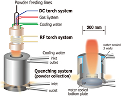
Figure 4. Schematic representation of a DC plasma torch used for plasma spraying. Reprinted from [49], with permission of AIP Publishing.
Download figure:
Standard image High-resolution image2.2.4. Plasma spray.
In conventional plasma spraying, a thermal plasma torch (DC or ICP) provides the energy required to melt the powdered feedstock material (diameters in the 10–100 µm range). Powders are injected radially (DC torches) or axially (ICP torches) into the plasma where particles are heated, melted and accelerated towards a substrate (figure 5). Upon contact with the substrate, partially-melted and melted droplets flatten and solidify, forming splats. Thick coatings (1–500 µm) result from the stochastic buildup of several splat layers, as illustrated in figure 5. Although finely structured or nanostructured coatings could be obtained from reduced-size feedstock powders, conventional carrier gas injection of solid nanoparticles within the plasma jet is inefficient: the flow rates required to impart sufficient momentum to the nanoparticles interfere detrimentally with the plasma [50]. Nanostructures are generally obtained with nanoparticle suspensions or precursors in solution as feedstock; the resulting processes are named SPS and SPPS, respectively [51]. Nanoparticles are formed in-flight from the precursors in SPPS, which reduces the health risks associated with their handling. In both processes, the liquid feedstock (suspension or solution) is injected in the plasma and complex plasma-liquid interactions dictate the coating microstructure in a 3-step process: (i) droplet fragmentation and solvent vaporization, (ii) surface precipitation and pyrolysis (in SPPS) and iii) acceleration and heating of nanoparticles/melted droplets to form a coating onto a substrate [52]. The spraying conditions in SPS and SPPS can be adjusted to form either dense or highly porous, cauliflower-like, coatings.
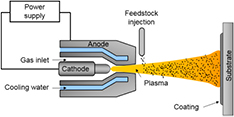
Figure 5. Schematic representation of a DC plasma torch used for plasma spraying.
Download figure:
Standard image High-resolution imagePlasma spray is a promising process to deposit binder-free electrode materials for LIB. In this case, the substrate consists of a flexible metal foil that will act as a current collector for the Li-ion battery. The feedstocks can be powders, suspensions or solution precursors of active materials that will be melted in-flight to form a coating onto the current collector, eliminating the need for a subsequent casting of the active material with a polymeric binder. Examples are provided in section 3.
Plasma spray physical vapor deposition (PS-PVD) is similar to conventional plasma spray, but the chamber pressure is reduced to values down to  kPa. At high plasma torch powers, this ensures that all the feedstock material is vaporized, enabling the deposition of a coating from the vapor phase [53]. In fact, columnar coatings similar to those obtained by electron beam physical vapor deposition (EB-PVD) have been produced by PS-PVD, albeit with larger deposition rates. It is also possible to rapidly quench the vapors to form nanomaterials, similarly to what is achieved with an ICP torch.
2.3. Non-thermal plasmas
As mentioned earlier, non-thermal plasmas are characterized by the condition  . In some illustrative examples, the electrons are heated by the electric field to tens of thousands of kelvin, the heavy particles remaining close to ambient temperature. This distinctive attribute of non-thermal plasmas is particularly interesting to modify temperature sensitive materials; even at low bulk temperatures, the electrons have sufficient energy to impart dissociation and ionization to molecules and atoms. Energetic species generated include ions and free radicals, reactive atoms such as atomic O, excited atomic states and photons. Several non-thermal plasma sources have been considered to enhance the performance of lithium-ion batteries. The most common, including closely related processes, are briefly reviewed below.
2.3.1. Glow discharge and atmospheric pressure glow discharge.
A glow discharge is a self-sustained luminous plasma generated between two electrodes to which a DC voltage is applied (figure 6). The electrodes are usually located inside a low pressure chamber (0.1–10 Torr). This simple and inexpensive plasma source produces electrons, excited molecules, atoms and ions that efficiently trigger selective chemical reactions. This is useful for the treatment of surfaces, sputtering and film deposition. The cathode region of the discharge is used for sputtering and deposition, whereas the negative glow will be preferred for chemistry [54]. However, the glow to arc transition limits the power that can be coupled into a glow discharge (if an arc discharge forms, the current must be increased to sustain the power, which in turns lead to the thermalization of the gas as in a DC plasma torch). To avoid the glow to arc transition, one can used either pulsed nanosecond discharges or RF discharges.
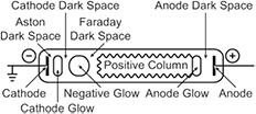
Figure 6. Structure of a glow discharge in a long tube. Reprinted from [41], with permission of Cambridge University Press.
Download figure:
Standard image High-resolution imageGlow discharges are also limited to low gas pressures unless they are operated in fast flows, leading to a plasma source commonly referred to as atmospheric pressure glow discharge plasma jet or torch. Note that dielectric barrier discharges (DBD) operated at atmospheric pressure can also be configured in such a way that the discharge looks like a glow (absence of microdischarges). These are often interchangeably called glow discharge plasma jet or DBD plasma jet.
2.3.2. Dielectric barrier discharge.
In a dielectric barrier discharge, the electrodes are excited by an AC (0.5–500 kHz) driving voltage. A dielectric covers one or both electrodes, or can be introduced in the low pressure discharge cavity, which prevents the formation of an arc (figure 7); in fact, the discharge is self-extinguished by the charge build-up on the surface of the dielectric before an arc could strike. At atmospheric pressure, DBD discharges are filamentary, each individual filament consisting in a breakdown channel called streamer or microdischarge. At lower pressures and higher frequencies, homogeneous diffuse glow discharges are obtained; they are referred to as RF glow discharges [55]. DBDs are simple to operate at powers greater than DC glow discharges.
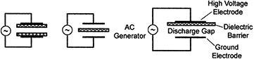
Figure 7. Basic barrier discharge configurations. Reprinted from [55], with permission of Springer. © Plenum Publishing Corporation 2003.
Download figure:
Standard image High-resolution image2.3.3. Radio-frequency and microwaves plasmas.
Non-thermal radio frequency plasmas are usually generated by capacitively coupling the RF electromagnetic field (1–500 MHz, commonly 13.56 MHz since it is a worldwide dedicated industrial, scientific and medical radio band) into the discharge cavity. They are referred to as capacitively coupled plasmas (CCP). In a CCP, a RF generator is connected to the electrodes, which may not be covered by any dielectric, as opposed to a DBD. Electrodes can be inside (figure 8) or outside the discharge cavity. Throughout the RF range, the electrons are able to follow the instantaneous RF field whereas the heavy particles cannot, creating nonequilibrium conditions interesting to stimulate chemical reactions in low-temperature conditions [39]. RF-CCP can also generate plasma jets called RF atmospheric glow discharges or atmospheric-pressure plasma jets (APPJ). CCPs have found several applications in plasma-enhanced chemical vapor deposition (PECVD) of silicon-based materials among others, which makes them interesting for LIB anode materials. When further increasing the frequency in the 0.5–10 GHz range, one reaches the microwave (MW) band and generates microwave plasmas. At the commonly used 2.45 GHz frequency, the corresponding wavelength (12.24 cm) is comparable to most plasma reactor sizes. If the MW frequency equals the electron cyclotron frequency, power absorption is maximized. The absorbed power in a RF or MW discharge also depends on the electron-neutral collision frequency and, consequently, on the pressure. Coupling is more efficient at lower pressures (electromagnetic waves with frequencies below the electron plasma frequency are reflected, which is proportional to the square root of the electronic density), but microwave discharges are also possible at atmospheric pressure. In this case, the energy will be coupled via the skin effect, but with a skin depth much thinner for MW compared to RF [54]. Other distinctions between RF and MW plasmas are reviewed elsewhere [56]. The most common configuration of microwave discharges has a rectangular waveguide crossing the discharge cavity enclosed in a dielectric.
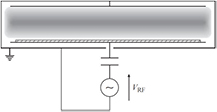
Figure 8. Schematic of a capacitively-coupled plasma reactor. Reprinted from [39], with permission of Cambridge University Press.
Download figure:
Standard image High-resolution image2.3.4. Plasma-enhanced chemical vapor deposition and atomic layer deposition.
Coatings and films can be produced by plasma-enhanced chemical vapor deposition (PECVD). In such processes, the plasma works as a source of specific chemical radicals that are deposited on a substrate. To sustain large deposition rates, relatively high pressures and flow rates are required, which challenges the stability of the plasma discharge. Stable parallel-plate RF-CCP discharges are often used for this task. Amorphous silicon, silicon dioxide and carbon nanotubes have been successfully grown by PECVD, although not specifically targeting LIB applications. When cycling the RF-plasma, chemical reactions can be sufficiently well controlled to deposit thin films with atomic layer precision at low temperatures. The process is called plasma-enhanced atomic layer deposition (PEALD).
2.3.5. Magnetron sputtering and pulsed-laser deposition.
Sputtering is a process in which atoms are ejected from a surface owing to energetic ion bombardment. The presence of the magnetic field, perpendicular to the electric field, increases power absorption, a suitable feature to sputter material. This is done by trapping electrons within a magnetic field near the target, increasing the efficiency of the ionization process (electrons travel or spiral over longer distances) and allowing plasmas to be both generated at lower pressures and confined near the target with a higher density of ions. Ejected atoms become the source for a following thin film deposition. Atoms can be directly deposited without further modification (physical sputtering) or can react with other chemically active species while in flight in the plasma (reactive sputtering). Non-thermal plasma sources employed in sputtering processes are generally DC discharges for conductive films (DC planar magnetrons), and RF-CCP discharges or RF-driven planar magnetrons for insulating films. A DC planar magnetron is a glow discharge in which the negative plasma glow is trapped in the magnetic mirror formed by magnetron magnets (figure 9) [42]. Atoms can also be ejected from a target (material to be deposited) by other means, including electron and laser beams. In the latter case, a high-energy pulsed laser beam strikes the target surface, vaporize and ionize the material into the plasma state. The technique is called pulsed-laser deposition (PLD).
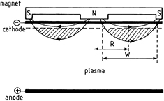
Figure 9. Schematic representation of a planar magnetron discharge, indicating the magnetic field lines and the trapping of electrons in a magnetic ring. Reprinted from [42], Copyright (2002), with permission from Elsevier.
Download figure:
Standard image High-resolution image2.4. Spark plasma sintering
Spark plasma sintering uses pulsed-DC current with the simultaneous application of moderate uniaxial pressure to sinter powder compacts in a graphite die. Advantages include shorter holding times, lower temperatures and reduced pressure to achieve dense materials. Mechanisms proposed to account for the enhanced sintering often rely on the hypothesis of a spark plasma generated between particles. That being said, there are now major concerns regarding the existence of this spark plasma discharge [57, 58]. As such, spark plasma sintering will not be further considered here, although it is a promising process to synthesize electrode materials for LIB [59, 60].
3. Plasma processes for electrode materials
3.1. Cathode materials
3.1.1. Layered lithium metal oxides.
The versatility of thermal plasma processing for LIB electrode materials was shown in a recent report where the authors synthesized lithium metal oxides (Mn, Co, Cr) in a single step, using an ICP torch with an applied power of 20 kW [61]. Powdered precursors (Li2CO3 and metal oxide) were injected into the plasma using Ar as carrier gas and a mixture of Ar and O2 as the plasma forming gas. In the case of LiCoO2, the particles obtained where found to have a size distribution between 50–80 nm with polyhedral shapes such as pentagonal, hexagonal and quadrangular, all morphologies that could be interesting for electrochemical testing. In fact, the electrochemical performance of electrodes can be tailored through particle morphologies since the crystal structure of a given compound has an important influence on the ion diffusion path [62–65].
Electrodes are conventionally prepared by casting a slurry containing the active material, carbon black and a polymeric binder and solvent on a current collector, generally Al, Ni or Cu foil and dried at 80–110 °C overnight. In the electrode preparation, the binder has the function to provide mechanical stability to the electrode, but it does not participate to the electrochemical reactions, adding an inert weight to the electrode. In this sense, direct deposition of the active material onto the current collector can simplify the electrode processing since the preparation of thin films is generally achieved in one step. Moreover, eliminating the passive binder has the potential to increase the energy density of LIBs. LiCoO2 thin film electrodes were deposited by various plasma processes [66–68] and sputtering [69–71]. In this sense, a recent report showed the preparation of nanostructured LiCoO2 electrode through the plasma spraying of metal Co on a stainless steel substrate. The deposition of 20–25 µm-thick coatings was achieved by 3–4 consecutive passes of the DC plasma torch. In a second step, the as-prepared Co coating was covered with a 1 M LiNO3 solution and thermally treated at 810 °C under ambient conditions at atmospheric pressure and no additional gas supply [72]. Samples were treated for different time periods, from 10 s to 12 min, and XRD analysis showed that, after 5 min, hexagonal LiCoO2 with space group R3m was already formed. LiCoO2 electrodes thermally treated for 5 and 12 min were electrochemically tested, showing similar electrochemical performances, with a discharge capacity  mAhg−1 (75% of the nominal capacity). This capacity decreased with subsequent charge-discharge cycles, most likely due to the dissolution of Co in the electrolyte caused by the lack of carbon coating that would increase the electronic conductivity of the active material and promote the formation of a passivation layer capable of preventing parasitic reactions with the electrolyte.
Improving the electrode performance by adding homogeneous and thickness-controlled coating on particles is key to the development of more stable electrodes, a feature that can be achieved by plasma processes. Such is the case of the deposition of carbon layers on the surface of LiCoO2 by PECVD [73]. The two-step process consisted in (i) preparation of a pellet electrode by mixing LiOH, H2O, and Co(OH)x precursors that were heated at 900 °C for 12 h in air and later mixed with synthetic graphite and polyvinylidene fluoride (PVDF), and (ii) the deposition of a carbon coating on the pellet electrode by reduction of ethylene using a glow discharge (PECVD process) with a chamber pressure of 0.08 Torr and a voltage of 1.2 kV. SEM and XPS confirmed the homogeneous deposition of a 0.1 µm-thick carbon layer that was characterized as diamond-like carbon using Raman spectroscopy. Additional to carbon coatings, different metal oxides have been deposited onto LiCoO2 [74–79] to effectively prevent direct contact with the electrolyte solution. The objective is to suppress phase transitions, to improve the structural stability and to decrease the disorder of the cations in the crystal sites. For example, commercial LiCoO2 was coated with ZnO by PECVD [80]. The room temperature process used diethyl zinc ((C2H5)2Zn) as precursor and a RF plasma power of 200 W. During ZnO deposition, LiCoO2 particles were mixed using a rake-shaped mixer inside the reaction chamber, which allowed the formation of uniformly distributed ZnO nanospheres on the surface of the particles and resulted in a coating of  nm. Charge and discharge cycling was performed between 3.0–4.5 V to evaluate the effect of the ZnO coating. It was shown that during the first few cycles, ZnO coating had no effect on the electrochemical performance of the oxide when compared to uncoated sample. However, optimally coated samples showed better capacity retention over prolonged cycling, the ZnO layer being effective to prevent the dissolution of Co in the electrolyte.
Taking advantage of the versatility and fast synthesis of materials by means of plasma technologies, other layered lithium metal oxide compositions suitable for electrochemical storage have been investigated. For example, Li(Ni1/3Co1/3Mn1/3)O2 was prepared by a plasma-assisted solid-state method [81], in which a RF discharge in oxygen increases the reaction kinetics. The same group considered sulfur doping by mixing a Li(Ni1/3Co1/3Mn1/3)O2 powder with thiourea and exposing the mixture to a RF discharge in argon [82]. The doped material showed higher initial discharge capacity, better cycleability and an improved performance at high temperature [82]. Carbon coatings were also successfully deposited onto Li(Ni1/3Co1/3Mn1/3)O2 using microwave PECVD [83].
3.1.2. Spinel lithium manganese oxide.
Spinel LiMn2O4 has also been largely investigated and used as positive electrode material for commercial LIB applications. Recent report on the synthesis of the spinel has targeted the control of both the particle size distribution and the morphology to enhance its electrochemical performance, which generally shows a low cycleability due to the dissolution of Mn3+ in the electrolyte. Nanosized LiMn2O4 with well-defined polyhedral morphology was synthesized using a plasma-enhanced low temperature solid-state strategy (PE-LTSS) (see figure 10) [84]. Starting materials (MnO2 and LiOH) were initially ball milled and later injected into the PECVD tube furnace that was set at 500 °C with an applied RF power of 200 W. Oxygen was flown into the furnace for 30 min to complete the reaction. The electrochemical performance of LiMn2O4 was tested on a coin cell against Li metal and LiPF6 in ethylene carbonate as electrolyte, and compared to a conventional solid-state-prepared LiMn2O4. Sample produced by this plasma-enhanced method yielded an initial discharge capacity of 130 mAhg−1 and retention of the starting capacity of 95.5%, while the one prepared by solid-state reaction only achieved 115 mAhg−1 and a capacity retention of 75.6%. Such improvement in the electrochemical performance was attributed to the finer particle size, narrower particle size distribution and controlled morphology.
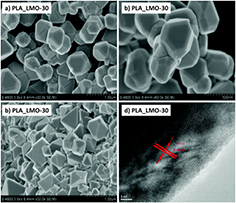
Figure 10. Some physical properties of the samples PLA-LMO-30 and LMO-4h: (a) and (b) SEM images of PLA-LMO-30 show highly aggregated nano-particles. Scale bars: 1 µm (a), 500 nm (b); (c) SEM image of LMO-4 h. Scale bar: 2 µm; (d) HR-TEM images of PLA-LMO-30. Reproduced from [84], with permission of The Royal Society of Chemistry.
Download figure:
Standard image High-resolution imageAlso, Li2MnO3 nanowires were synthesized by first producing MnO2 nanowires using the solvo-plasma technique [85], followed by a solid-state reaction. The protocol consisted in the deposition of an aqueous slurry of MnO2 and KCl on a stainless steel substrate. The water was removed from the substrate at 70 °C and exposed to an atmospheric microwave plasma jet [86] for 5 min. To complete the synthesis, the powder was removed from the substrate and alloyed with LiOH at 480 °C. The electrochemical performance of Li2MnO3 nanowires presented a pseudoplateau at 4.1 V, corresponding to the Li extraction from spinel LiMn2O4. This evidenced a phase transformation of the electrode material upon cycling, as shown in the charge-discharge profile (figure 11). The material was found to have great capacity retention upon cycling at different C rates going from 1 C to 20 C and capacities ranging from 135 mAhg−1 to 110 mAhg−1. The electrochemical performance of the Li2MnO3 nanowires represent an improvement when compared to other morphologies [87–89].
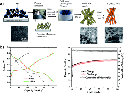
Figure 11. (a) Schematic of the solvo-plasma process for synthesizing MnO2 nanowires followed by solid-state alloying to prepare Li2MnO3 nanowires. (b) Charge-discharge capacity curves and cycleability of Li2MnO3 nanowires at 5 C. Reproduced from [85], with permission of The Royal Society of Chemistry.
Download figure:
Standard image High-resolution imageAs mentioned earlier, carbon has proved to enhance the electronic conductivity of the active materials, which are otherwise highly insulating. DC-pulsed plasma treatment of laminated LiMn2O4-carbon black composite electrodes improved the stability of the active material upon cycling [90]. Commercial LiMn2O4 was mixed with carbon black and PVDF, later laminated on Al foils and dried at 120 °C for 24 h to obtain electrodes  µm-thick. After drying the electrode, a 400 V pulsed-DC plasma treatment was carried out for different exposure times under an O2 atmosphere. XRD patterns showed that, after plasma processing, the LiMn2O4 crystal structure is kept. Still, the morphology was affected. Untreated LiMn2O4 particles showed well-defined grain separations, while treated particles presented a smooth surface where the boundaries between grains disappeared, forming a coating. Electrochemical tests of the two samples showed that plasma-treated LiMn2O4 had a capacity retention of 60% upon 40 cycles, while the untreated LiMn2O4 only retained 40% of its initial capacity after 40 cycles. Such improvement in the cycleability of the electrode is attributed to a variation in morphology that led to the formation of a protective layer, analogous to conventional carbon or metal oxide coatings.
In a similar report, Wang et al [91] showed that it is possible to deposit a graphite coating onto commercial LiMn2O4 using magnetron sputtering. Typical slurry containing the active material, carbon black and PVDF in n-methyl-2-pyrrolidone (NMP) was casted on an Al foil, followed by a drying step. The graphite coating was deposited on the surface of the as-prepared film by magnetron sputtering (figure 12) with different growth times (from 0 to 60 min), aiming to form a graphite layer on the surface that would prevent Mn from dissolving into the electrolyte upon electrochemical cycling. XRD pattern showed no changes in the corresponding spinel peaks, indicating that the crystal structure was preserved during the plasma treatment. Moreover, TEM images allowed identifying and measuring the graphite coating, which was found to have a thickness around 50 nm. Electrochemical performance of the different films prepared at 0, 10, 30 and 60 min treatment time showed that carbon-coated LiMn2O4 for 30 min presented the largest improvement in cell polarization and capacity retention. This is attributed to an optimal carbon layer that allowed good electrode wettability and also protected LiMn2O4 from HF attack (HF results from the electrolyte decomposition), avoiding changes in the surface structure of the electrode.
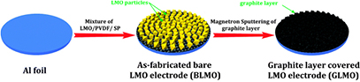
Figure 12. Schematic diagram for the preparation of the nano-thin graphite layer covered LiMn2O4 electrode. Reproduced from [91], with permission of The Royal Society of Chemistry.
Download figure:
Standard image High-resolution imageDirect deposition of active material on the current collector was also performed to obtain binder-free LiMn2O4 thin films in a two-step process: (i) sol-gel synthesis of a LiMn2O4 thin film electrode and (ii) pulsed-DC plasma treatment [92] under pure O2 atmosphere to induce the formation of a dense nanocrystalline surface layer that would increase both the stability and the ionic conductivity of the active material. Plasma treatment was carried out for different time periods (0, 5, 30 min) and the resulting electrodes were electrochemically tested at elevated C-rates that went from C/5 to 45 C. Samples treated for 5 and 30 min showed a 65% capacity retention at 10 C and 32% at 35 C, while non-treated sample showed a capacity retention of only 50% and 12%, respectively.
3.1.3. Olivine lithium iron phosphate.
The synthesis of LiFePO4, usually carried out via solvothermal or the sol-gel methods, has also been addressed by innovative plasma technologies. For example, electric discharge assisted mechanical milling (EDAMM) was used to produce LiFePO4 [93]. In this milling process, stoichiometric amounts of mixed precursors (Li2CO3, FeC2O4·2H2O and (NH4)H2PO4) were fed into a reaction vessel adapted with two curved stainless steel electrodes (figure 13). The pulverization of the powder was obtained through the vibration of one of the electrodes at 10 Hz for different time periods, while an AC power was supplied to generate  kV, 70 Hz-impulses at 100–300 mA. The discharge, in the form of a glow or a spark, is known to accelerate the sintering process [94]. As such, fast synthesis of the olivine was demonstrated; after only 1 min of reaction, the characteristic peaks of LiFePO4 were already observed in the XRD pattern, together with unreacted precursors. Pure phase was obtained after a 10 min reaction, as shown in figure 14. Although the particle size distribution of the samples was found to be irregular, changing the vibration time changes the morphology, opening the door for deeper studies on the tuning of particle crystallinity, shape and size.
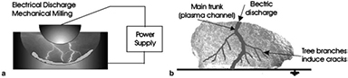
Figure 13. Schematic of EDAMM reaction vessel detailing (a) how an electric discharge is produced between the vibrating stainless steel plunger and mill floor and (b) the interaction of an electric discharge with a powder particle. Reprinted from [93], Copyright (2006), with permission from Elsevier.
Download figure:
Standard image High-resolution image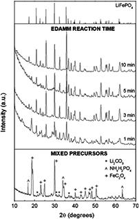
Figure 14. XRD patterns of LiFePO4 mixed precursor powders and after EDAMM reaction for 1, 3, 5 and 10 min. JCPDS ICDD card 40-1499 (LiFePO4—triphylite mineral) at top of figure. Reprinted from [93], Copyright (2006), with permission from Elsevier.
Download figure:
Standard image High-resolution imageOur research group recently reported the ICP torch synthesis of LiFePO4 nanospheres of approximately 50–100 nm in diameter, using FePO4·2H2O, LiOH and oxalic acid as precursors (conventional sol-gel precursors) [48]. During the synthesis, the sheath gas consisted in a mixture of H2 and Ar to provide a reducing atmosphere that would prevent iron from oxidizing. In a single step procedure, carbon-coated LiFePO4 particles were prepared (figure 15(a)). Oxalic acid in the precursor solution acted as a carbon source that led to the formation of a coating onto the nanoparticles, likely improving the electrical conductivity of the material. The possibility of preparing carbon-coated particles in a single step makes this process attractive for scaling up the production of such active materials. In fact, carbon coatings are usually deposited in a second step by the pyrolysis of organic precursors like sucrose, glucose, oxalic acid, ascorbic acid, etc, or by post-synthetic procedures such as chemical vapor deposition from toluene or physical vapor deposition [95, 96]. In the same report, we have detailed the preparation of plasma-sprayed LiFePO4 coatings (figure 15(b)) using a plasma torch equipped with a supersonic nozzle. Schematic view of the inductively coupled thermal plasma reactor used for the synthesis and deposition of LiFePO4 was presented in figure 3. Deposition was performed on a 50 µm-thick Ni foil and using the same solution of precursors as for the powdered LiFePO4. Conventionally-casted electrodes containing the plasma-prepared LiFePO4 powder were compared to the binder-free plasma-sprayed electrodes by means of cyclic voltammetry (figures 15(c) and (d)). Characteristic positive anodic peak (charging phase) around 3.5 V and a negative cathodic peak (discharging phase) between 3.2 and 3.4 V were obtained in both cases. The best reversibility was observed for the plasma-obtained LiFePO4 powder.
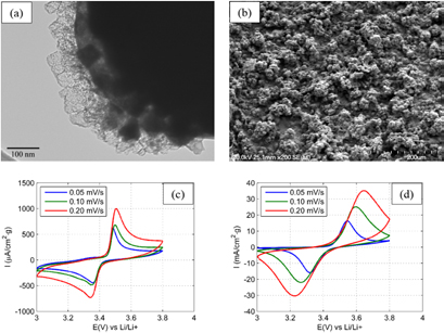
Figure 15. LiFePO4 powders (a) and coatings (b) synthesized or deposited by means of RF-ICP. Cyclic voltammetry of (c) LiFePO4 cathode made of plasma-synthesized powders dispersed in PVDF and (d) binder-free, plasma-deposited LiFePO4 cathode. Reprinted from [48], © 2015, with permission of Springer.
Download figure:
Standard image High-resolution imageAnother approach for the synthesis of LiFePO4 has been reported by Dobbelaere et al [97]. Plasma-enhanced atomic layer deposition was performed on different 3D platinum-coated silicon substrates to produce micropillar electrodes. The synthesis was carried out by the sequential exposure to trimethyl phosphate (TMP), O2 and tert-butylferrocene (TBF) inside a plasma, as shown in figure 16(a). The first two compounds created a phosphoric acid-like precursor species on the surface of the substrate, while the latter completed the formation of the olivine. During the process, the plasma power was set to 200 W and 300 W for TMP and O2 plasmas, respectively. A schematic representation of the proposed reaction path is shown in figure 16(b). The authors developed a comprehensive study on the reaction path and its dependence on the temperature used; the optimal deposition was obtained at 300 °C. The electrochemical performance of the prepared micropillar was compared to a planar electrode at different C-rates (see figure 16(c)). The capacity of the 3D electrode was found to be 20 times higher than that of a planar electrode, which was attributed to the increase in surface area for the micropillar electrodes and, in both cases, capacity faded almost linearly with the increase in C-rate.
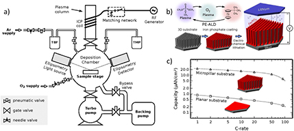
Figure 16. (a) Schematic drawing of a plasma-enhanced atomic layer deposition system. (b) Representation of the LiFePO4 deposition sequence. (c) Capacity as a function of the C-rate for iron phosphate films on a planar substrate (squares) and on a 3D-structured micropillar substrate (triangles). Reprinted with permission from [97]. Copyright (2016) American Chemical Society.
Download figure:
Standard image High-resolution image3.2. Anode materials
A vast research has been carried out using plasma technologies to produce negative electrodes. That covers promising electrode materials with considerably larger theoretical capacities than graphite, such as Si (4200 mAhg−1 for Li22Si5, 3580 mAhg−1 for Li14Si5) or Sn (994 mAhg−1), as well as carbon-based negative electrodes (hard carbon, SWCNT, MWCNT, graphite, graphene). Although carbon-based anodes are widely used in commercial Li-ion batteries, the preparation of carbon materials by means of plasma-based technologies represents a standalone topic itself and, therefore, these materials are intentionally excluded from this review. Other relevant publications are suggested to address the topic [98–100]. In the following, metal-based anode materials prepared by plasma technologies will be reviewed.
3.2.1. Silicon.
Silicon nanoparticles based anodes have been synthesized by plasma processes (PS-PVD, RF-ICP, DC arc plasma jet, PECVD, etc) over the last few years, as reviewed by Doğan and Van De Sanden [21]. Silicon anodes have a theoretical capacity of 4200 mAhg−1, an order of magnitude larger than that of graphite-based anodes. Still, this high capacity cannot be maintained for more than a few tens of charge/discharge cycles, as the lithiation process of silicon comes with a detrimentally large volume expansion (~300%) that results in mechanical damages and capacity losses. This volume expansion can be accommodated by controlling the size and morphology of the nanostructured silicon, which can be achieved by plasma processes.
Promising Si negative electrode material has been recently prepared by a DC discharge between a Si bar and a Pt wire through a solution (electrolyte) [101]. A study of different electrolytes and different voltages was carried and, in most cases, spherical particles were obtained, as shown in figure 17. When the applied voltage was low (160 V for 0.1 M HCl and K2CO3), particle sizes smaller than 1 µm were obtained; for voltages above 200 V, the particles produced had an average diameter over 1 µm. In the presence of acidic electrolyte, crystalline SiO2 was obtained, while amorphous SiO2 resulted from basic electrolyte solutions. This synthetic method allows customization of particle size for anode applications.
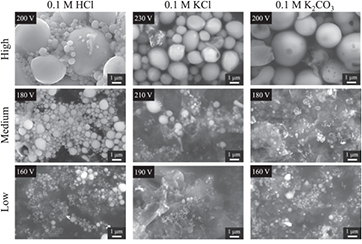
Figure 17. SEM image of Si particles produced in different electrolytes at different applied voltages [101]. Reproduced from [101]. © IOP Publishing Ltd. All rights reserved.
Download figure:
Standard image High-resolution imageIn the case of the work reported by Lamontagne et al [102], Si nanowires were synthesized by the carboreduction of silica fume in the presence of Al, Ni, Fe and Y2O3 as catalysts, using an ICP thermal plasma reactor similar to that shown in figure 3. The composition of the sheath gas went from He to a mixture of Ar and H2. In this work, it was shown that samples prepared without catalyst contained less Si and no Si nanowires were formed, while samples prepared using a metal catalyst showed a higher efficiency in the carboreduction of SiO2 to Si and in the growth of Si nanowires, as shown in figure 18. The hypothesized growth path of Si nanowires thus requires silicon to be solubilized in the catalysts in the high temperature zone and then precipitated as its solubility diminishes in the quenching zone. The nature of the catalyst also modified the growth of the nanowires: Al formed packed Si nanowires, whereas Ni and Fe favored an individual growth (see figure 18).
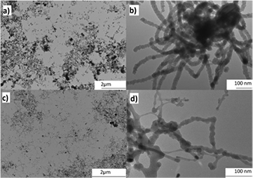
Figure 18. TEM images at low and high magnifications of Si nanowires grown in a RF-ICP reactor with Al ((a) and (b)) and Ni ((c) and (d)) as catalysts. Dark areas on low magnification images are agglomerations of nanowires. Reprinted from [102], © 2014, with permission of Wiley.
Download figure:
Standard image High-resolution imageA DC-ICP hybrid torch operating in PS-PVD mode (8 kW DC and 90 kW ICP) was employed by Kambara et al to produce Si, SiC and carbon-coated Si (core–shell) aggregates of 200–300 nm in size made of 20–40 nm particles at a throughput >350 g h−1 [50]. The feedstock consisted in metallurgical grade silicon powders with a mean diameter of 19 µm and CH4 gas was co-injected as a carbon precursor. The carbon-to-silicon ratio was found to have an incidence on the capacity, as shown in figure 19. The capacity fading of the electrode was found to increase as the C/Si ratio increased due to the irreversible formation of SiC.
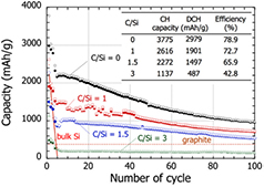
Figure 19. Cycling performance of batteries using PS-PVD powders with different C/Si molar ratios. Solid and open marks represent the capacity after lithiation and delithiation, respectively. The initial charge (CH) and discharge (DCH) capacities are listed in the inset table. Reprinted from [50], with permission of AIP Publishing.
Download figure:
Standard image High-resolution imageComposite metal-carbon materials have also been considered. For example, spherical Si particles can be obtained by RF thermal plasma in one step by injecting Si powder with Ar as carried gas [103]. A representation of the Si synthesis is shown in figure 20, together with a secondary step to disperse the prepared powder in a carbon matrix. Si nanospheres (SiNS) dispersed in carbon by ball milling of a mixture Si/C (4:1) showed an outstanding electrochemical performance, with an initial capacity of 2388 mAhg−1. Moreover, after 100 cycles, the remaining capacity was 778 mAhg−1, two times the theoretical capacity of graphite.
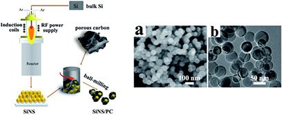
Figure 20. The preparation process of SiNS and SiNS/PC composites by RF thermal plasma. (left). FEG-SEM (a) and TEM (b) images of SiNS (right). Reproduced from [103], with permission of The Royal Society of Chemistry.
Download figure:
Standard image High-resolution imageSi nanoparticles [104] were prepared in a matrix of carbon nanotubes using an arc plasma. The authors used two powder feeders to separately inject the precursors: (i) Si was injected directly into the plasma torch, where particles were evaporated to form nanoparticles, and (ii) commercial MWCNT were injected in a cooler downstream region to preserve their structural integrity. After treatment, the Si-MWCNT nanocomposite collected in the reactor chamber was found to have Si nanospheres uniformly distributed along the column of MWCNTs, which resulted in a suppression of the detrimental Si volume expansion under electrochemical cycling and in a discharge capacity of 1447 mAhg−1. Composite Si/graphene nanosheets (Si/GNs) with a hierarchical structure, prepared using a plasma-assisted milling process similar to EDAMM, also showed interesting cycling capabilities, maintaining a capacity of 1000 mAhg−1 over 350 cycles (figure 21) [105]. For a capacity of 1000 mAhg−1, the electrode was cycled at different C-rates and showed good capacity retention, mainly attributed to the small particle size and hierarchical morphology accommodating stress/strain during the lithiation/delithiation process and buffering the volume changes upon cycling.
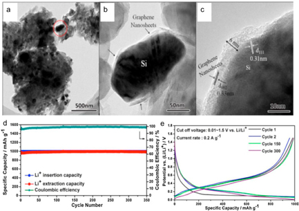
Figure 21. (a) TEM image of the Si/GNs hybrid. (b) and (c) High magnification TEM images of the zone delineated by a dotted circle in (a) showing the Si nanoparticles coated and connected by the GNs. (d) Cycling performance and (e) discharge/charge profiles of the Si/GNs hybrid with a capacity of 1000 mAhg−1. Reprinted from [105], Copyright (2016), with permission from Elsevier.
Download figure:
Standard image High-resolution image3.2.2. Tin.
Sn/SnO2/MWCNT nanocomposites have been prepared by means of thermal evaporation of metallic Sn onto MWCNT buckypaper, followed by a subsequent RF plasma oxidation process aiming at reducing the SnO2 volume changes associated to the lithiation/delithiation process [6]. Plasma oxidation of the Sn films was conducted using a mixture of O2 and Ar in a 1:1 ratio, a total chamber pressure of 1.6 Pa, a RF power of 80 W and a duration of 45 min. The electrochemical performance of the Sn/SnO2/MWCNT free-standing electrode was tested during charge-discharge cycles, which showed a maximum discharge capacity or 1544 mAhg−1. Upon 10 cycles, the capacity retention was 51% (788 mAhg−1), while it decreased to 24% (374 mAhg−1) after 100 cycles.
A similar approach was taken by Thomas et al [106]. in the synthesis of SnO2-graphene nanocomposites. Initially, highly porous graphene nanosheets were synthesized by decomposition of acetylene in a microwave PECVD process at 700 °C for 30 min, followed by the sputtering of a 3 nm-thick layer of gold over the vertically-deposited graphene nanosheets (GNS). Annealing of the gold-coated GNS led to the formation of 5 nm gold nanoparticles that served as catalyst for the formation of SnO2 nanowires. SnO2 was deposited using reactive electron beam evaporation of Sn in an oxygen-rich atmosphere onto the substrate, which was held at 620 °C. Figure 22 shows a series of SEM images depicting the different stages of the preparation of the nanocomposite. The electrochemical performance of the as-prepared electrode was first evaluated by cyclic voltammetry between 0.01–2.0 V, where the characteristic graphene peaks were identified during cycling. Such observation indicated that Li+ intercalated into the GNS. The first discharge and charge cycles showed capacities of 1335 and 4930 mAhg−1, respectively, exceeding theoretical values. Such high capacities were attributed to the contribution of SnO2 nanowires and of the porous GNS. However, large capacity fading was observed in the second cycle, most likely due to the irreversible decomposition of SnO2 and of the electrolyte. Subsequent cycling resulted in roughly 70% of the initial charge-discharge capacities, as can be seen in figure 23.
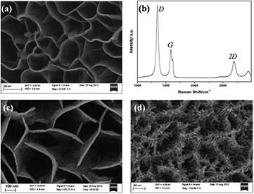
Figure 22. (a) Scanning electron microscopy image (SEM) of graphene nanosheet (GNS) on copper substrate, (b) Raman spectrum of GNS, SEM image of (c) gold deposited over GNS and (d) early stages of growth of SnO2 nanowires. Reproduced from [106], with permission of The Royal Society of Chemistry.
Download figure:
Standard image High-resolution image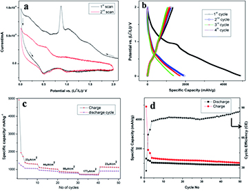
Figure 23. (a) Cyclic voltammetry of SnO2NW@GNS, (b) galvanostatic charge/discharge profile of SnO2NW@GNS, (c) rate performance of the SnO2NW@GNS electrode, and (d) coulombic efficiency versus cycle number of the SnO2NW@GNS electrode. Reproduced from [106], with permission of The Royal Society of Chemistry.
Download figure:
Standard image High-resolution imageAnother strategy to prevent Sn to suffer a dramatic volume change during its charge-discharge process is to alloy Sn with transition metals. The insertion of an inactive element would act as a support to avoid losing the microstructure. DC arc discharge has been used to synthesize binary alloys Sn–M (M = Fe, Al, Ni) using a mixture of powdered Sn and M that was compressed and used as anode [107]. Sn–M was evaporated by the arc discharge and condensed after a temperature drop. The alloys prepared showed a typical spherical morphology with a metal core and an oxide shell, as observed with high resolution TEM. The particle size distribution was in the range of 50–150 nm. Sn–Fe was found to have lower charge and discharge capacities (256 mAhg−1 and 338 mAhg−1, respectively). However, great cycleability was obtained after 20 cycles with a capacity fading of only 11%.
3.2.3. Lithium titanates.
The synthesis of titanates by means of pulsed-laser deposition [108], APPJ [109] and ICP [110, 111] was also considered. Starting with solid Li2CO3 and TiO2 precursors that were axially injected into a 40 kW plasma discharge, Quesnel et al obtained nanoparticles, nanowires and nanoplatelets by changing two main experimental parameters: the Li:Ti ratio and the sheath gas composition (mixture or Ar and H2) [111]. It was found that the presence of H2 promoted the formation of nanosized materials and that the production yield could be increased with the addition of seeding material (in this case Li4Ti5O12).
3.2.4. Cobalt oxide.
Tummala et al built on the binder-free plasma spray process of LiCoO2 coatings described above and reported the synthesis of a flexible Co3O4 electrode [112]. A cobalt acetate tetrahydrate solution was radially injected into the plasma plume and sprayed onto a stainless steel substrate, producing a flexible Co3O4 coating, as shown in figure 24. The as-prepared electrode was electrochemically tested in a coin cell versus Li/Li+ at C/10, which delivered an initial discharge capacity of  mAhg−1. Subsequent charge and discharge cycles resulted in capacities close to the theoretical value (890 mAhg−1). Although a large capacity is obtained, considerable capacity fading is observed when increasing the cycling rate to C/2, 1.25 C and 16.5 C, most likely due to the lack of a carbon additive that would increase the electronic conductivity and alleviate the volumetric expansion undergone with continuous cycling. It is expected that, by adding a carbon source to the precursor mixture or in a second step, the electrochemical performance of Co3O4 could be improved.
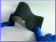
Figure 24. Solution precursor plasma deposited flexible Co3O4 electrode on a stainless steel sheet (SS304) current collector. Reprinted from [112], Copyright (2012), with permission from Elsevier.
Download figure:
Standard image High-resolution image4. Plasma processes for separators
Another critical component of a battery is the separator; a solid membrane placed between the two electrodes that prevents their physical contact, but allows the transport of ions during the charge and discharge processes. Usually, a separator is a polymeric membrane or a non-woven fabric matrix that is electrochemically inert and that would ideally show elevated wettability, good chemical, mechanical and thermal stability, appropriate porosity, and high electrolyte retention [113].
Among the polymers investigated, polypropylene (PP), polyethylene (PE) and polyethylene oxide (PEO) are mostly used [114]. Recent attempts to improve the performance of PP and PE separators have been addressed by surface modification using a plasma treatment with Ar/O2 [115] or acetonitrile [116]. Such plasma exposures increased the hydrophilic character of the surfaces and, therefore, increased the electrolyte retention and wettability when compared to the non-treated surface. In addition to enhancing the hydrophilic character and wettability, grafting charged vinyl sulfonic acid and diallyldimethylammonium monomers to PE using an atmospheric pressure RF discharge was also recently shown to increase the mobility of lithium ions and to improve the thermal stability and mechanical strength of the separator [117].
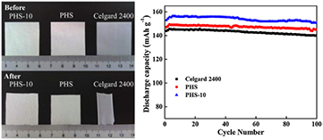
Composite membranes, where metal oxides were anchored to the matrix of the separator, can also be prepared [115]. SiOx was deposited on the surface of the separator by means of PECVD in an effort to improve the thermal stability (that is, to prevent polymer thermal shrinkage) and the electrolyte-philicity of the membrane. Experiments carried at 120 and 140 °C with the SiOx-coated separators resulted in a shrinkage resistance of ~98% for a 70 nm coating [115]. Another plasma-treated composite membrane has been reported to have SiO2 nanoparticles anchored in its matrix [118, 119]. In this study, PP nonwoven fabric were plasma-treated with 2,2,3,3,4,4,5,5-octafluoropentyl methacrylate for different periods of time to increase the interfacial compatibility [119]. Composite membranes were prepared in a two-step process: (i) preparation of a slurry containing PVDF, hexafluoropropylene (HFP) and SiO2 and (ii) coating the plasma-treated PP with the slurry. A complete study of the microstructure and properties of the prepared separators showed that plasma treatment longer than 10 min resulted in severe etching of the surface, which is unfavorable for battery applications. Additionally, thermal stability and shrinkage of the separators was evaluated. PP-treated membranes coated with PVDF-HFP and SiO2 (samples labeled 'PHS-10') presented better mechanical strength and thermal stability, showing 3% of shrinkage at 100 °C for 30 min, while the other PP sample showed 6% and Celgard 2400 43% of shrinkage under the same conditions, as illustrated in figure 25. The electrochemical performance of a LiFePO4/Li coin cell using the different separators was also considered. The cell assembly with PHS-10 delivered an average capacity of 155 mAhg−1 (Celgard 2400 and PHS separator showed 143 and 147 mAhg−1, respectively), and showed great capacity retention upon 100 cycles, as also seen in figure 25.
Figure 25. Variation of thermal shrinkage of separators as a function of temperature (left) and cycle performance of LiFePO4/Li half-cells assembled with different separators at a charge/discharge condition of 0.2 C/0.2 C with an operating potential ranging from 2.5 to 4.2 V (right). Reprinted from [119], Copyright (2015), with permission from Elsevier.
Download figure:
Standard image High-resolution image
Other metal oxides have been studied in the search of better composite separators. TiO2 [120] has been deposited on PP membranes following two key steps: (i) plasma pre-treatment of PP to generate active groups on the surfaces and (ii) atomic layer deposition of ultrathin titanium oxide films. The increase in the number of deposition cycles of TiO2 decreased the contact angle of the separator: bare PP resulted in a contact angle of 48º and PP after 150 ALD cycles had a contact angle of 25º, showing an improved wettability. Similarly, Al2O3 coating layers were deposited on commercial PE separators by means of plasma treatment, producing a hydrophilic surface that led to an improvement in the electrochemical performance of a LiMn2O4/PE separator/Li metal cell [121].
5. Discussion and perspectives
The examples presented above have emphasized the versatility of plasma technologies in the preparation of LIB components with both thermal and non-thermal plasmas. The latter can produce high quality materials, but their broad adoption is unlikely at this time owing to very low production rates (<0.1 g h−1). On the other hand, cathode materials such as LiFePO4 and lithium metal oxides (e.g. layered LiCoO2 and spinel LiMn2O4), and anode materials such as Si and Li4Ti5O12, can all be synthesized by means of ICP torches at high throughput (up to kg h−1). The resulting nanopowders have diverse morphologies (spheres, truncated octahedra, polyhedra, nanowires, etc) that look promising for fast Li+ intercalation/desintercalation. The microstructure and the electrochemical performance of such materials prepared from conventional and thermal plasma-based routes are compared in table 2.
Table 2. Comparison of microstructure and electrochemical performance of electrode materials for LIB.
| Sample | Synthesis method | Morphology | Particle size (µm) | Initial capacity (mAhg−1) | Capacity retention (n cycles, C rate) |
|---|---|---|---|---|---|
| LiCoO2 | Coprecipitation [122] | Nanoflakes | 0.5–15 | 178 | 83% (100, 1 C) |
| Hexagons | 0.05–0.08 | — | — | ||
| Thermal plasma [61] | Thin films | >20 | 107 | 82% (15, 0.5 C) | |
| LiMn2O4 | Hydrothermal [123] | Cubes | 5–10 | 100 | 80% (500, 10 C) |
| Thermal plasma [61] | Polyhedral | 0.05–0.08 | — | — | |
| PE-LTSS [85] | Polyhedral | 0.4 | 130 | 95% (100, 2 C) | |
| LiFePO4 | Solvothermal [63] | Nanoplatelets/hierarchical | 1.0 | 111/167 | 95% (50, 0.1 C) |
| Thermal plasma [48, 93] | Spherical | 0.05–0.1 | — | — | |
| Cotton-wool | 0.04–0.05 | 80 | 100% (100, —) | ||
| Si | Vapor–liquid–solid process [124] | Nanowires | <0.1 dia. >5 length | 4200 | 75% (10, C/20) |
| Thermal plasma [49] | Nanoparticles | 0.02–0.04 | 3775 | 26% (100, 0.1 C) | |
| Li4Ti5O12 | Ball-milling assisted solid-state [125] | Mesoporous structure | 0.008 | 175 | 82% (50, 10 C) |
| Thermal plasma [111] | Nanowires | <0.4 | — | — |
Table 2 illustrates an important gap in research that must be addressed to enable thermal plasma technologies for LIB: that of electrochemical data. Indeed, most studies reported have adopted a 'proof-of-concept' approach with little or no electrochemical testing. The plasma-produced materials are foreseen as promising, but most publications lack of deep electrochemical characterizations that would include impedance measurements and cyclic voltammetry to evaluate the reduction and oxidation potentials, the reversibility and the internal cell resistance. The charge-discharge profiles and the long term capacity (over hundreds of cycles to assess capacity fading at various C rates up to 10 C) should also be reported, especially for LiFePO4 and LiCoO2. When analyzing the few studies for which these data were reported, one can conclude that thermal plasma synthesized LIB materials usually have an initial capacity that is smaller than the theoretical one, while showing important capacity fading over the firsts 10–100 cycles. As such, there is room for improvement which may come from:
- (1)a better control of the particle morphology and size distribution: nanoparticles with small diameters (~20–40 nm) can be produced in thermal plasmas, but it generally requires reactor geometries that promote growth with uniform residence time and that prevent agglomeration upon collection. The use of catalysts and in situ carbon coating has also been suggested.
- (2)a reduction in impurities (nature and quantity): the non-selectivity of thermal plasmas towards targeted reactions and materials requires a systematic identification and quantification of impurities as they may have detrimental effects on the electrochemistry. Thermodynamic simulations at high temperatures proved to be useful in predicting secondary reactions and self-seeding was successfully suggested to increase yield.
- (3)the addition of a carbon coating to the active materials: the carbon coating acts as a multi-functional layer between the active materials (anode and cathode) and the electrolyte to improve the solid–electrolyte-interface (SEI) film, to increase the electronic conductivity, to protect the active materials from electrolyte corrosion and to limit nanoparticle aggregation [97]. Carbon precursors are easily co-injected with the active material precursors in thermal plasma processes. As discussed earlier, some active LIB materials (e.g. LiFePO4, LiCoO2 and Si) were successfully carbon- or metal-oxide-coated by injecting carbon or metal precursors into the plasma, allowing an increase of the cathode electronic conductivity and enhancing its stability towards the electrolyte while cycling.
- (4)a better accommodation of volume changes upon Li-ion cycling, especially for Si- and Sn-based anode materials: Optimizing parameters such as nanoparticle size, porosity, binder composition and composite structure with embedded carbon nanotubes or graphene have shown encouraging results. For example, a microwave PECVD synthesis process of SnO2-graphene nanocomposites was shown to be effective in limiting the volumetric changes usually observed in SnO2 anodes.
Another innovative approach considered and that could enable plasma technologies in LIB is the preparation of binder-free electrodes. For example, the active materials precursors can be plasma-sprayed directly onto the current collector, as was shown for Co3O4 and LiFePO4. It simplifies the preparation of the electrodes, while avoiding the use of slurry containing PVDF and NMP to conventionally cast the active materials. Benefits are twofold: less solvent and higher energy density. Binder-free electrodes can also be obtained by magnetron sputtering, as shown for LiCoO2 thin films. Still, the design and the optimization of binder-free coating/thin film remain in their early stages. Improving the coating/film porosity (percentage and pores connectivity) and adding carbon layers that fully cover the surface of the deposited active materials are required to achieve the expected charge-discharge capacities and cycleability.
6. Conclusion
It makes no doubt that plasma technologies can produce or modify LIB components with performances similar, if not superior, to conventional methods. The morphologies of active materials resulting from plasma processes are particularly interesting, but breakthroughs in material composition originating from plasma technologies are possible, but not likely. Anodes, cathodes and separators can be plasma-processed in one or two steps, while reducing the use of solvents and eliminating post-synthesis procedures.
Still, if plasma technologies are to penetrate the LIB manufacturing market, they will have to adapt to existing assembly lines. As such, plasma-synthesized or modified powders can directly replace the powders obtained from sol-gel or solid-state routes. The challenges in this case are the production scale-up (non-thermal plasmas) and quality control (thermal plasmas). Moving from vacuum to atmospheric conditions increases the plasma density and the production rate, but it comes with gas heating and less selectivity. Atmospheric pressure plasmas are driven by gas-phase collision mechanisms for which the reaction/collision kinetics are not well understood outside the carbon- and silicon-based anode materials. The ion density, electron temperature and nucleated nanoparticle temperature are critical parameters to follow to obtain the desired crystalline phase. This is especially true for complex layered oxides and polyanions. For binder-free electrodes, flexible coatings and thin films will have to be deposited onto the current collector with better consistency, especially if plasma-sprayed. This dusty process may not be directly compatible with existing LIB assembly lines. In any case, the cost per mAhg−1 produced will be a concern to launch plasma-based production of LIB active materials.
The combination of plasma technologies to well established processes, like the electric discharge assisted mechanical milling, is also attractive for the smart design of synthesis procedures for LIB materials with desired crystal structure, size and morphology in shorter processing times. Furthermore, the treatment of surfaces by means of non-thermal plasmas has been considered to modify the polymeric membranes used as separators. Various plasma sources were shown to increase electrolyte retention of PP and PE membranes through an enhancement of the electrolyte-philicity and wettability of the polymers. The interfacial adhesion between the electrodes and the separator is also improved, which enhances the cycle performance of the resulting lithium-ion battery. Similar enhancements of the electrolyte-philicity and wettability can be obtained by anchoring metal oxides to non-woven fabric matrices, while improving the membrane thermal stability.
Acknowledgments
The financial support by the Natural Sciences and Engineering Research Council of Canada (NSERC RGPIN-2014-05928) and the Université de Sherbrooke is gratefully acknowledged.