
Abstract
This work presents molecular dynamics and Monte Carlo simulations aimed at developing an understanding of the formation of core–shell Cu–Ag nanoparticles. The effects of surface and interfacial energies were considered and used to form a phenomenological model that calculates the energy gained upon the formation of a core–shell structure from two previously distinct, non-interacting nanoparticles. In the majority of cases, the core–shell structure was found to be energetically favored. Specifically, the difference in energy as a function of the radii of the individual Cu and Ag particles was examined, with the assumption that a core–shell structure forms. In general, it was found that the energetic gain from forming such a structure increased with increasing size of the initial Ag particle. This result was interpreted as a result of the reduction in surface energy. For two separate particles, both Cu and Ag contribute to the surface energy; however, for a core–shell structure, the only contribution to the surface energy is from the Ag shell and the Cu contribution is changed to a Cu–Ag interfacial energy, which is always smaller.
Export citation and abstract BibTeX RIS
1. Introduction
Bimetallic nanoparticles have optical, magnetic and catalytic properties that are often different from the bulk materials. A wide range of applications is currently being investigated, including hydrogen storage, fuel cells, shape-memory alloys and materials joining. Any application, however, is strongly dependent on the shape and structure of the specific nanoclusters, which are, in turn, strongly dependent on the individual components that make up the clusters.
While a number of different final structures are possible from the mixture of two metal nanoparticles (i.e. janus particles or well-mixed clusters), many bimetallic clusters reportedly produce core–shell structures [1]. The core–shell arrangement is generally formed when either one metal has a lower surface energy than the other (following a general rule of lower surface energy coating higher surface energy) or there is an atomic radius mismatch such that the smaller species tends towards the core to relieve strain, while the large atoms move to the shell [1–4].
While bimetallic clusters can be formed through various processing methods, including gas, liquid and matrix supported routes [1], recently, a synthesis route in which low level heating (as low as 423 K) of distinct Ag and Cu nanoparticles was reported to lead to the formation of a core–shell structure [5]. While this fabrication route was feasible for ∼6 nm Ag particles and ∼12–15 nm Cu nanoparticles, optimization of these processes to obtain ideal sizes or size ratios of the particles that will lead to an ideal core–shell structure is of interest; however, synthetic efforts would be time consuming and a model to assist in defining the operation space would be of interest.
In this work, the formation of the core–shell structure from a surface energy perspective was undertaken, with examples elucidating the optimal sizes from both Monte Carlo (MC) and molecular dynamics (MD) simulations. The results of these simulations were fitted to simple forms, which were then used to develop a phenomenological model of the energetics of the core–shell structure. In particular, the energy gained upon the formation of this structure was examined as a function of the radii of the two initial nanoparticles to guide synthesis efforts.
2. Simulation details
MD simulations were performed with the LAMMPS code using the embedded-atom method (EAM) with an AgCu alloy potential developed by Williams et al [6]. A time step of 1 fs with a velocity Verlet algorithm was used for the integration with the temperature controlled by a Langevin thermostat. The results obtained from the experimental aspect of this project [5] indicated that the core–shell structure forms at temperatures as low as 423 K over a timescale of minutes. Modeling this process is far beyond the timescales accessible by MD simulations. It is, therefore, appropriate to raise the temperature of the simulations in order to increase the diffusive motion of the atoms. The phase diagram of AgCu binary alloys is a simple eutectic, with a eutectic temperature of 1053 K; however, the EAM potential used underestimates this temperature as 935 K [6]. For the MD runs, the goal was to increase the temperature as high as is feasible for increased diffusion, while remaining below the eutectic line. Initial simulations at 723 K indicated that the initial formation of the core–shell structure occurred rapidly but progression to a final equilibrium structure was excessively slow. Therefore, the results of the core–shell formation that are run were presented at a temperature of 923 K.
MC simulations were performed with an in-house code [7], in which Metropolis moves were accomplished by particle swaps with an additional random translation of up to 0.2 Å in any direction. The temperature of the MC simulations was set at 800 K, which is somewhat lower than what was used in the MD models. These results are compared with those at higher temperatures, and while no qualitative difference at 923 K (i.e. the temperature of the MD simulations) could be elucidated, runs at 1200 K (far above the eutectic temperature) showed complete melting and mixing of the system. Therefore, the 800 K MC results represent the structures found at temperatures below the eutectic, without the necessity of using as high a temperature as is feasible, as is the case for the MD simulations. The results are qualitatively similar as there are no structural changes or phase transformations in this region of the phase diagram. Runs were continued until visual inspection indicated an obvious trajectory towards a final state, although these simulations could not establish an equilibrium structure.
3. Simulation results
Simulations began with distinct Ag and Cu (see figure 1) nanoparticles of specified radii that were cut from a large block of fcc material. While it is not expected that experimentally synthesized nanoparticles are spherical, particularly at small sizes, this starting geometry is reasonable for assessing the effects of different surface energies on a final state, and allows us the flexibility to develop a phenomenological model. It is expected, however, that final state geometries will more accurately represent experimental systems (see, for example, the faceting in figure 1(c)). Because of the large barriers for diffusion reported for Ag along Cu surfaces [8], these simulations only show the general trend of the shell formation. Select snapshots of the simulation results over time are shown in figure 1. Runs for the MD calculations began with 5 nm particles of Ag and Cu that were touching at a single interface along the (0 1 0) face (figure 1(a) in contact, after energy minimization, prior to dynamics). Figures 1(b) and (c) show the same particles after 35 ns of runtime (T = 923 K) and clearly show that the Ag atoms diffuse along the outer surface of the Cu particle (preferring step edges on the {1 1 1} plane) and not through the interior. This is in agreement with literature calculations from Baletto and co-workers [8], which reported that the lowest energy barrier for Ag atom on a Cu surface exists for jumps along {1 1 1} facets. This is also in agreement with the previously reported experimental results [5].

Figure 1. Snapshots from the MD simulation at (a) 0 ns, (b) 35 ns and (c) 35 ns in cross-section. Silver atoms are shown as green and copper atoms as red.
Download figure:
Standard image High-resolution imageThe slow formation of the Ag shell essentially moves the timescale out of the range of MD simulations, even at the elevated temperatures employed. Therefore, MC simulations were investigated to arrive at a better picture of the ending state. As described above, the MC code used here performs random particle swaps (in this case, attempting to exchange Cu and Ag atoms at each MC step) with a small (<0.2 Å), random translation. Therefore, the process of changing the initial shape of the structure (e.g. from two spherical particles as in the MD simulations to a single spherical core–shell structure) would be exceedingly slow. Instead, a spherical structure, in which one side was composed entirely of Cu atoms and the other entirely of Ag atoms, was used and is hereafter referred to as a janus-NP. The results from the MC simulations are shown in figure 2. The initial janus-NP shown (figure 2(a)) consists of a particle with a radius of 5 nm that is divided spatially which results in an unequal number of Ag and Cu atoms.
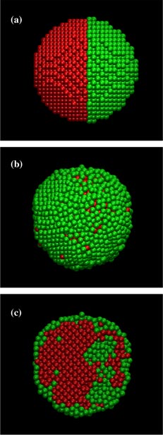
Figure 2. Snapshots from the MC simulation after (a) 0 MC steps, (b) 400 million MC steps and (c) 400 million MC steps in cross-section. Colors are the same as in figure 1.
Download figure:
Standard image High-resolution imageAfter 400 million MC steps, figures 2(b) and (c) show the state of the simulation. Note: this was not a true intermediate state as in MD simulations but rather a snapshot of what the preferred final configuration was trending towards. As can be observed, the preferred mechanism is to have the Ag atoms move from core positions to the shell, while Cu atoms move into the core. As the simulation progressed, fewer Ag atoms were present in the 'core' region and progress towards the final state became asymptotically slower. While these simulations have not yet reached an equilibrium structure, it is believed that the lowest energy state has been unambiguously identified as the Cu–Ag core–shell structure. While simulation methods exist that will further push this system towards a true energetic minimum [1], these have not been pursued. The results shown in figures 1 and 2 show an obvious trend towards a core/shell structure, and this structure has been identified as favorable in both simulations and experiments [1, 5]. With the clear indication that this AgCu EAM potential also favors the correct structure, it is more instructive to calculate properties of this system for use in a phenomenological model than to continue the simulations.
Since simulation and experimental data indicated a preferential arrangement of Ag along Cu {1 1 1} planes [5, 8], the interfacial energies of Ag and Cu slabs (periodic in x and y) were calculated with varying crystal orientations. Slabs of Ag{1 0 0} (37 × 5.1 × 2.6 nm), Ag{1 1 1} (37 × 5.1 × 3.5 nm), Cu{1 0 0} (37 × 5.1 × 2.0 nm) and Cu{1 1 1} (37 × 5.1 × 3.3 nm) were generated and energy minimized. For the {1 0 0} planes, the perpendicular directions were [0 1 0] and [0 0 1], while for the {1 1 1} planes, they were [1 1 −2] and [−1 1 0]. There was no mutual rotation of the slabs considered for the interface calculations, and the dimensions perpendicular to the interface (i.e. x and y) were chosen such that they are reasonably close to multiples of the lattice constants of the two metals. This is in an attempt to minimize the contribution of the strain energy to the interfacial energy. Because the calculated energies agree well with previous calculations by other investigators (see below), this procedure appears to be reasonable. The energy of an individual slab will have two components as shown in the following equation:

where Eslab is the total (minimized) energy of the slab, N is the number of atoms, Ecoh is the cohesive energy, A is the cross-sectional area and γs is the surface energy. The cohesive energy is calculated from an energy minimization of a 500 atom cube (with periodic boundary conditions in all three dimensions) of the individual components. Based on these calculations, the cohesive energies were found to be −2.85 eV/atom for Ag and −3.54 eV/atom for Cu, which are in agreement with literature values [6, 9]. The various combinations of the Ag/Cu surfaces were then put into contact and the interfacial energies calculated using the equation

By calculating N × Ecoh for each slab separately, and calculating EAgCu from an energy minimization of the interface, the value for γAgCu was calculated, and the results are shown in table 1. These data indicate that Ag{1 1 1}/Cu{1 1 1} has the lowest energy of all the interfaces studied, explaining previous results. The calculated interfacial energies were in good agreement with previous interfacial energies that were calculated using a different EAM potential; the energies of semicoherent interfaces were found to be 0.231 J m−2 for {1 1 1} and 0.530 J m−2for {1 0 0} [10]. For comparison, in table 1 we also show the surface energies of the various orientations of Ag and Cu, as calculated for this EAM potential. Note that these surface energies are significantly higher than the interfacial energies.
4. Model development
Based on the results from MD and MC simulations, a model that predicts the energy gained by the formation of a core/shell structure by two distinct nanoparticles is developed. The major assumptions that are made in order to construct this model are that both the initial and final geometries of the nanoparticles are spherical, and that the particles are both pure metals. While these assumptions are unlikely to be accurate depictions of experimentally synthesized nanoparticles (or the core/shell structure they might form), they enable determination of both the initial surface energies as well as the final interfacial energies without the difficulties of understanding the effects of, for example, impurities, solvents/coatings, facets, kinks or steps. This model, then, is a simplification of the energetics of core/shell formation that only accounts for the effects of surface and interfacial energies.
The energy of a lone, spherical nanoparticle is given by equation (3), similar to equation (1), but in this case with only one surface:

with A being the surface area of the sphere (see equation (7)) and γsphere being the surface energy of the spherical particle. This surface energy is different from γs in equations (1) and (2) because of the variety of exposed faces in the sphere. The energy for two non-interacting nanoparticles is given by

Similarly, the energy of a core/shell particle would then be given by a combination of the spherical nanoparticle equation as shown in equation (5), where there is no longer a contribution from the surface energy of the Cu, as the entire surface of the Cu core is contacting the inner surface of the Ag shell:

In equation (5), the surface energy contribution of the Ag in the core/shell structure will be different from that for the bare particle in equation (3), because of the different radius of the two structures (i.e. the same amount of Ag will form a larger sphere when coating a Cu particle). To make this distinction clear, the surface energy in this case is denoted as γshell. The interfacial energy is now denoted as γsphere(AgCu), to differentiate the value in a spherical geometry from that used in equation (2). When equation (5) is reduced to its analytical components, the relationship shown in equations (6)–(7) is developed:


where rm is the radius of the nanoparticle, ρm is the number density of the metal m and Am is the surface area of the nanoparticle. In equation (6), the number of atoms N is written in terms of the density of the element and the volume of the particle, while equation (7) ensures that the surface and interfacial energies in equation (5) are independent of the surface area. The values of γsphere are determined by calculating the energy of nanoparticles, using equation (3) to eliminate the contribution from the cohesive energy, and fitting the data as a function of nanoparticle radius. Fits for Ag and Cu nanoparticles are shown in figure 3, with γsphere(Ag) = 1.024 J m−2 (0.063 891 eV A−2) and γsphere(Cu) = 1.486 J m−2(0.092 733 eV A−2). These values, while slightly larger, are close to the calculated slab surface energies shown in table 1. The comparison is not exact given that the nanoparticles have a variety of exposed surface textures.

Figure 3. Surface energy contribution of Ag (red squares) and Cu (blue circles) nanoparticles as a function of the surface area. Calculated values are shown as squares and fits are shown as solid lines.
Download figure:
Standard image High-resolution imageThe final parameter necessary for equation (5) is the interfacial energy γsphere(AgCu) between the Cu core and the Ag shell. The energy of a number of core–shell particles with varying size Ag shells (initial Ag nanoparticle radii of 10, 14, 20 and 25 nm) and Cu cores (radii 5, 10 and 14 nm), both cut from single crystal bulk materials, was calculated in order to arrive at a value for γsphere(AgCu). As with the single nanoparticles shown in figure 1(a), these particles have a variety of exposed surface textures, since the bulk single crystal is oriented with the x, y and z axes aligned along the [1 0 0], [0 1 0] and [0 0 1] directions, respectively. The calculation of a universal value for γCuAg is difficult, as smaller radii Cu cores lead to a contribution from the curvature, while smaller Ag NPs lead to a dependence on the final shell thickness. While these contributions should be negligible given large enough initial particles, these calculations show that γsphere(AgCu) ranges from about 0.70 to 0.74 J m-2(0.044 to 0.046 eV A−2). These calculated values of γsphere(AgCu) are higher than, but comparable to, the largest value shown in table 1, as discussed above for the values of γsphere(Ag) and γsphere(Cu). For the predictions of the theory, the larger value of γsphere(AgCu) was used as this will only overestimate the interfacial energy, and thus underestimate the energy difference between the core–shell configuration and two separate nanoparticles. Specifically, the energy gained upon core–shell formation was determined by equations (8) and (9):


where γshell and γsphere refer to the surface energies in the shell and original spherical geometry, respectively. Since γsphere(Cu) is always larger than γsphere(AgCu) the second component of equation (9) should be negative (see below). This last statement justifies the selection of the largest values of γsphere(AgCu); larger values will lead to an upper bound of Egain.
These terms represent all that is necessary to calculate Egain as a function of the radii of the two initial particles. A contour plot of the calculated Egain is shown in figure 4. The plot shows that the ideal choice for core–shell formation is to utilize relatively small Cu particles as the core with larger Ag particles to act as a shell. For any value of rCu, the energy gained increases (i.e. becomes more negative) as rAg increases. However, for certain large rCu values with small rAg, there is no energy gained, and the core–shell structure becomes unfavorable. Note that this plot is less accurate when either rcu is small (due to curvature effects in the surface energies) or rAg is small (because of incomplete shell formation; see discussion below).
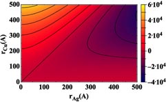
Figure 4. Energy gained (eV) from the formation of a core/shell structure plotted as a function of the initial (i.e. unjoined) particle radii.
Download figure:
Standard image High-resolution imageTo better understand the results of figure 4, it is useful to consider the separate contributions from equation (9); the first bracketed term represents the difference in the Ag surface energy upon forming a shell from a separate NP, while the second bracketed term is the difference between the Ag/Cu interfacial energy and the surface energy of a bare Cu NP. For a given rAg the first term increases with increasing rCu. The reason for this lies in the difference in the outer radius of a core–shell as compared with a bare particle. The radius of a core–shell is
 , indicating that as rCu becomes larger (compared with rAg) the final core–shell radius remains close to that of the initial Cu NP. This is a result of the larger area that must be coated by the same number of Ag atoms, resulting in a thinner shell overall. The larger final radius leads to a larger contribution to the surface energy from the Ag in the core–shell, as opposed to the smaller Ag NP. Note that this contribution to equation (9) is never negative. In contrast, the second term is always negative, and becomes larger (i.e. more negative) with increasing rCu because, as discussed above, the interfacial energy is always lower than the Cu NP surface energy. There is no dependence on rAg in this term, as would be expected from this simple model, but this is exactly where the inaccuracies of the model in figure 4 arise. With smaller initial rAg, it is impossible for the Ag to fully coat the Cu, resulting in incorrect estimates of three terms in equation (9). Specifically the contribution of Cu surface energy of the core–shell structure is underestimated (in fact, it is completely ignored), while the Ag surface energy and the AgCu interfacial energy are both overestimated. It is, therefore, expected that the values shown in figure 4 are an upper bound of the energy gain. The shell thickness is given by

which indicates that for most cases with rAg < rCu the shell will be incomplete (i.e. the thickness is less than the size of a Ag atom), and thus figure 4 can only be used as a guide for optimal initial conditions. As an example, it is clear from our experiments [5] that Ag and Cu NPs with initial radii of 6 and 12–15 nm will form core–shell structures, although figure 4 would imply that this is not energetically favorable. Clearly, the difference in surface energy results in Ag wetting the Cu, regardless of the initial size of the particles.
It is possible to modify equation (9) to include a correction factor for incomplete coverage. The fractional coverage, f, can be estimated by

where αAg is the lattice constant of Ag, and the
 estimates the spacing between neighboring {1 1 1} layers. This factor modifies equation (9) to be

in the cases where f ⩽ 1.0 only; when f = 1.0, equation (12) reduces to equation (9). A contour plot of the modified energy is shown in figure 5, in which many of the erroneous effects of fractional coverage (specifically when rAg < rCu) are removed, indicating an energetic gain for most combinations of radii.

Figure 5. Energy gained (eV) from the formation of a core/shell structure including estimates of the effects of fractional shell coverage.
Download figure:
Standard image High-resolution image
5. Summary
While the formation of a core–shell structure has been previously understood from the standpoint of competing surface energies and atomic sizes, the model developed here is the first demonstration of the energetics of formation, particularly with the radii of the initial particles taken into account. This model indicates that for the AgCu core–shell arrangement, relatively smaller particles of Cu and larger particles of Ag are the most energetically favorable to form a core–shell structure. In addition, this structure was calculated to be the most favorable to form along {1 1 1} faces, which has also been seen experimentally. This is an extension of the experimental work that demonstrated the formation of a core–shell structure from initially distinct particles, rather than through a co-deposition process [5]. It is expected that this model can prove useful, both for directing synthesis routes for nanoparticles, as well as for choosing specific metallic species which are more or less likely to form such core–shell structures, depending on the desired use.
Acknowledgments
This work was supported by the Laboratory Directed Research and Development (LDRD) program at Sandia National Laboratories. Sandia National Laboratories is a multi-program laboratory managed and operated by Sandia Corporation, a wholly owned subsidiary of Lockheed Martin Corporation, for the US Department of Energy's National Nuclear Security Administration under contract DE-AC04-94AL85000.