
Abstract
Refreshable Braille displays require many small diameter actuators to move the pins. The electrostrictive P(VDF–TrFE–CFE) terpolymer can provide the high strain and actuation force under modest electric fields that are required for this application. In this paper, we develop core-free tubular actuators and integrate them into a 3 × 2 Braille cell. The terpolymer films are solution cast, stretched to 6 μm thick, electroded, laminated into a bilayer, rolled into a 2 mm diameter tube, bonded, and provided with top and bottom contacts. Experimental testing of 17 actuators demonstrates significant strains (up to 4%) and blocking forces (1 N) at moderate electric fields (100 MV m−1). A novel Braille cell is designed and fabricated using six of these actuators.
Export citation and abstract BibTeX RIS
1. Introduction
The development of a full page refreshable Braille display requires many, small diameter actuators to move the pins. Commercially available displays are expensive, bulky and limited to two lines of Braille characters. The piezoelectric bending actuators used in these devices require a significantly larger area than the Braille pins themselves. Designing a more compact, portable system would enable the blind community to interface freely with computers and have access to the internet and e-mail.
The recent advancements in the field of electroactive polymers (EAPs) make those materials a promising solution for tactile display applications [1]. The main challenge resides in designing a miniature actuator that can meet both the Braille displacement and force requirements while operating at low voltage. The designs that have been investigated include multilayer stacked actuators that contract [2, 3], bistable electroactive polymers that use temperature control [4], dielectric elastomer membranes that buckle [5, 6], and PVDF bending bimorph actuators coupled with hydraulic fluids [7].
Compared with other actuator materials, the electrostrictive P(VDF–TrFE) based terpolymers and their blends offer several unique advantages including large transverse electrostrictive strains (∼5%) and high elastic modulus (∼1 GPa) which can be exploited for compact actuation devices [8–10]. These actuator polymers can be fabricated into thin films (down to 1 μm) enabling low operation voltages for practical commercial devices.
Tubular actuators are commonly used as artificial muscles [11–16], but have not been considered for tactile devices. Their large diameter and soft structure, usually requiring internal support springs, make them unsuitable for Braille applications. In this paper, we present a new rolled actuator that meets all of the Braille display specifications and explain the corresponding fabrication process. Seventeen actuators made from P(VDF–TrFE–CFE), a ferroelectric polymer, are tested experimentally and a cell containing six Braille characters is successfully demonstrated.
2. Actuator design
2.1. Concept
Figure 1 shows a schematic diagram of the P(VDF–TrFE–CFE) cylindrical actuators developed in this paper. They consist of an electroded bilayer film that is rolled into a tube. An external electric field causes the film to contract through the thickness and extend longitudinally in the actuation direction. The positive and negative electrodes are offset, allowing an electrical contact at each end of the actuator. The number of layers, diameters, and length of the actuator are designed to avoid buckling under maximum blocking force. This means that the actuator does not need an internal core, setting it apart from previous devices. The P(VDF–TrFE–CFE) ferroelectric polymer used in this application provides large electrostrictive strain [17] (3.5% at 100 MV m−1) and high modulus (∼109 N m−2) for an easily read display.
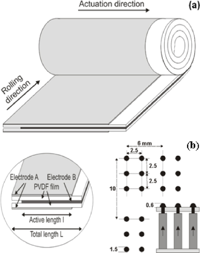
Figure 1. Actuator and Braille cell design: (a) rolled actuator concept (close-up inset shows four offset electrodes) and (b) Braille cell.
Download figure:
Standard image2.2. Design
The dimensions of the roll actuator are based on a standard Braille cell [18], shown in figure 1(b). The center-to-center distance between two adjacent dots is 2.5 mm, and the tip displacement must exceed 0.5 mm while withstanding a minimum force of 0.5 N. The blocking force and free stroke of the actuator at the maximum operating voltage are designed to satisfy these specifications.
The actuator displacement

where l is the active length of the actuator and ε is the strain at the applied voltage. The blocking force is

where t and W are the thickness and rolling width of the single layer film, respectively, and E is the Young's modulus of the material in the axial direction (0.8 GPa).
The actuation voltage is chosen to provide an electric field of 100 MV m−1 and a corresponding strain of 3.5% without causing film breakdown. The average thickness of the PVDF films is 6 μm so the actuation voltage is 600 V. With 3.5% strain an active length of 15 mm provides the required 0.5 mm pin displacement. To account for manufacturing and material variability, a length of 30 mm is used. To enable a simple, core-free design, the actuator must be structurally stable under the applied blocking force. Due to the large length/diameter ratio, Euler buckling is a likely failure mode so lateral support is provided in the Braille cell design.
3. Fabrication process
3.1. Solution casting
The polymer films are created using a solution blending and casting technique. PVDF powder mixed with CFE and TrFE is dissolved in a heated solvent solution. The solution is poured onto a glass substrate, left at rest for 12 h, and then placed in a conventional oven and then a vacuum oven above room temperature (∼80 °C) to eliminate any remaining solvent. Finally, the film is removed from the glass substrate using deionized water. This method is very cost effective and simple but it creates film with randomly oriented polymer chains. To maximize actuation strain, the polymer chains are aligned using a stretching process.
3.2. Stretching and annealing
After the casting process, the P(VDF–TrFE–CFE) film thickness is typically between 50 and 70 μm. To reduce the actuation voltage the samples are stretched down to a thickness of 6 μm. Stretching also aligns the polymer chains in the actuation direction, improving strain performance. Using either a linear or roll-to-roll stretching machine, the film, pulled in tension at both ends, is locally heated with a hot wire, allowing the film to stretch according to a user defined ratio.
The abrupt change in temperature near the hot wire creates residual stresses in the stretched film. Annealing relaxes the film by heating close to the melting temperature followed by slow cooling. Annealing also increases the crystalline phase content, which contributes to the electrostrictive strain and improves the elastic modulus.
3.3. Electrode deposition
For the electrode deposition step, the film is tensioned onto 7.5 cm × 10 cm metal frames using a repositionable spray adhesive as shown in figure 2. A mask is temporarily placed on top of the frame, delimiting an electrode pattern of 30 mm × 75 mm. A conductive polymer solution (CPS—Clevos™FE-T) was used as the electrode (blue area on the film in figure 2). CPS is deposited onto the film using an ultrasonic nozzle (Sonaer 130K50T). The electrode performance (conductivity and capacitance) increases with increasing electrode thickness but the strain performance degrades due to the additional passive constraint on displacement. The CPS spray time is adjusted to balance these opposing objectives. A thin gold layer is also deposited on the edge of the electrode pattern, to improve electrical contact at the ends of the actuator. For some of the actuators, aluminum electrodes are evaporated onto the polymer film instead of CPS.

Figure 2. PVDF film tensioned on a supporting frame with CPS and gold electrodes.
Download figure:
Standard image3.4. Lamination
Figure 3 schematically shows laminated bilayers with electrodes on three and all four sides. Four sided samples work well if the lamination is poor with gaps or air pockets. For high quality laminations, however, three sided samples exhibit higher strain because there is less passive electrode material constraining motion. Three sided samples are also easier to fabricate, requiring one less electrode deposition step. Simultaneous external pressure and heat are applied to both films for successfully lamination. The layers are compressed using a vacuum bag (∼10 cm Hg) and then placed in an oven. The temperature (100 °C) and heat exposure time (2 h) are optimized to maximize the interlayer bounding strength and equalize the measured capacitance between the three and four layer designs. The optimized lamination process gave bilayers with similar average capacitance (251 nF for 3 sided samples and 268 nF for 4 sided samples), indicating a high quality lamination. In theory, one could use only two electrodes in the bilayer if the final step in the vacuum oven provides a sufficiently high quality lamination of the rolled bilayer.

Figure 3. Bilayer lamination with electrodes on (a) 4 sides and (b) 3 sides.
Download figure:
Standard image3.5. Rolling
Rolling transforms the flat bilayer to a wound roll actuator. The bilayer is removed from the metal frame. Figure 4 shows a mandrel acting as a temporary core to wind the film around. During winding, the bilayer is pulled along a flat surface by the rotating mandrel with a weight on the film providing tension to minimize the formation of wrinkles. The mandrel temporarily adheres to the film during rolling using an adhesive. At temperatures above 80 °C the adhesive liquefies, allowing the core to be easily removed from the actuator after the lamination in a vacuum oven. To prevent unraveling, another adhesive is lightly deposited on the end of the rolled sample, permanently bonding the last two layers.
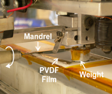
Figure 4. Automated mandrel for the rolling process.
Download figure:
Standard image3.6. Bonding and electrical contact
The last step of the actuator fabrication process is to heat the device at 90 °C in a vacuum oven for 90 min. The vacuum helps eliminate air pockets trapped in between layers during the rolling process and the heat bonds all the rolled layers together, improving the mechanical strength of the structure. Removing residual air in the actuator is essential to improve the voltage breakdown of the device. Lastly, steel balls are bonded on both electrode ends using conductive epoxy to serve as electromechanical contacts (see figure 5).

Figure 5. An example core-free rolled P(VDF–CFE–TrFE) actuator.
Download figure:
Standard image4. Experiments
4.1. Experimental set up
Figure 6 shows the experimental set up used to analyze the performance of 19 actuators fabricated using the process described above. A Trek 609E-6 high voltage amplifier, controlled by LabView, provides the actuation voltage. The displacement and blocking force are measured by a PolyTec OFV 534 laser vibrometer and a Transducer Techniques EBB-1 cantilever beam load cell, respectively. The current going through the actuator is also measured. An acrylic block is machined with 1.9–2.4 mm dia. holes to provide lateral support for the actuator. Galden fluid is pumped into the block to minimize arcing and improve heat dissipation. The steel balls of the actuator are contacted using a magnet on the bottom (positive end) that is fixed to the acrylic block and a magnet on the top that is soldered to a very thin (0.07 mm diameter) copper wire connected to ground.

Figure 6. Displacement and force measurement set up. (1) Laser vibrometer. (2) Load cell. (3) Actuator. (4) Supporting acrylic block. (5) High voltage input. (6) Ground. (7) Galden fluid supply.
Download figure:
Standard imageTable 1 shows the average and standard deviation of the parameters and performance of the 19 actuators fabricated and tested. The devices average 2 mm in diameter and 43.6 mm in height formed from bilayers averaging 11 μm in thickness.
4.2. Electrical measurements
The capacitance and loss of the actuators are measured using a precision LCR meter (HP 4284A). The theoretical capacitance

where ε0 is the electric constant, εr is the relative permittivity of P(VDF–CFE–TrFE), A is the active area of the actuator, and t the thickness of the single layer film. For the average parameters in table 1 and permittivity εr = 40, the expected value of capacitance is 290 nF. The actual measured capacitance is less than theoretically predicted, probably due to incomplete electroding of the bilayer surfaces. The loss is also relatively high due to resistance in the CPS electrodes.
4.3. Strain results
The voltage applied during initial strain testing ranged from 200 V to approximately 700 V in 50 V increments. Two of the nineteen actuators fabricated failed immediately at 200 V. Of the remaining 17 samples, 12 survived the entire experiment and the other 5 failed at various input voltages due to film defects.
Table 1. Core-free P(VDF–TrFE–CFE) terpolymer actuator properties.
| Property | Average | Deviation | Max | Min |
|---|---|---|---|---|
| Geometrical | ||||
| Length (mm) | 43.6 | 1.2 | 45.4 | 42.0 |
| Active length (mm) | 30 | 0 | 30 | 30 |
| Inner diameter (mm) | 1.35 | 0.20 | 1.50 | 1.1 |
| Outer diameter (mm) | 2.00 | 0.14 | 2.24 | 1.75 |
| Thickness of bilayer (μm) | 11 | 2 | 16 | 7 |
| Electrical | ||||
| Capacitance @ 20 Hz (nF) | 260 | 49 | 349 | 185 |
| Loss @ 20 Hz | 0.08 | 0.02 | 0.14 | 0.04 |
| Mechanical | ||||
| Strain at 100 V μm−1 (%) | 2.03 | 0.81 | 4.18 | 0.82 |
| Force at 100 V μm−1 (N) | 1.05 | 0.26 | 1.30 | 0.70 |
| Stiffness at 50 V μm−1 (kN m−1) | 4.15 | 1.16 | 6.04 | 2.77 |
Figure 7 shows the experimental results for two example devices. The voltage signal is ramped at 100 V s−1 until reaching the desired value (figure 7(a)). The signal is held constant for 60 s before being ramped back down to zero. Using a ramp input rather than a step input limits the maximum current during the charging process to about 0.1 mA (figure 7(b)). A step input of 650 V generates a current peak of approximately 2 mA, more than an order of magnitude higher. High currents are likely to cause heating at localized imperfections that ultimately lead to breakdown. Figure 7(c) shows the displacement response of the actuator peaking at more than 1.2 mm for an applied voltage of 750 V. Figure 7(d) shows the displacement of an Al-electroded actuator, in which a strain of 3% is obtained under 100 MV m−1. After a quick initial transient, the actuator continues to slowly extend. This extension eventually reaches a constant steady state value after approximately 600 s. When the voltage is turned off, the actuator quickly contracts and then slowly returns to zero displacement. This 'reversible creep effect' [19] has also been observed in piezoelectric materials.
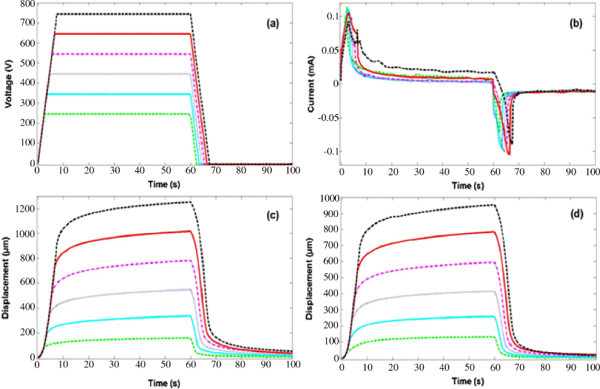
Figure 7. Experimental time response for an example actuator: (a) voltage, (b) current, (c) displacement and (d) displacement for an Al-electroded actuator.
Download figure:
Standard imageFigure 8 shows the average and standard deviation of strain versus electric field for the 17 actuators tested. At 100 MV m−1, the average strain is 2%, much lower than the performance expected from previously tested single layer P(VDF–CFE–TrFE) films [14]. The standard deviation is relatively large at medium and high strains. This variability can be explained by several factors. First, the actuators tend to move axially and transversely. The acrylic block constrains this transverse movement but does not entirely eliminate the associated reduction in the axial displacement. Second, the capacitance data also shows significant uncertainty, indicating variances in material properties and nonuniformity of the electrode deposition. On average, actuators with higher capacitance also produce higher displacement. Third, the adhesive deposited during the rolling process, although minimal, could restrain the axial displacement.
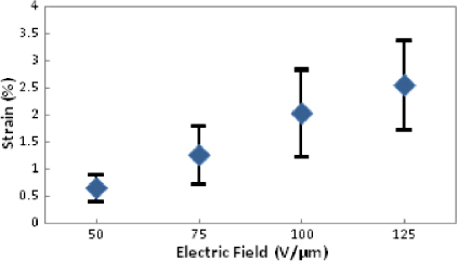
Figure 8. Experimentally measured strain versus electric field for 17 actuators (blue diamond is the mean value and error bars indicate ± one standard deviation).
Download figure:
Standard image4.4. Force results
Eight actuators are successfully tested for blocking force by positioning the actuator tip in contact with the load cell and applying the voltage time trajectory shown in figure 9(a). The voltage is ramped up, held constant for 30 s and ramped down. The blocking force results for one actuator are shown in figure 9(b). For most of the actuators, the response looks similar to this example for voltages less than 300 V. The blocking force rises until the applied voltage ramps down. The blocking force at that voltage is chosen to be the value just before the down ramp starts. For the example actuator at 400 V, however, the blocking force does not grow monotonically, peaking before the downward ramp. In this case, the blocking force produced by the device is higher than the critical Euler load of the structure and the tube bends laterally. The side walls of the acrylic block limit buckling to a certain extent but at 700 V the actuator fails and no longer withstands high loads.

Figure 9. Experimental time response for blocking force tests: (a) voltage and (b) blocking force.
Download figure:
Standard imageFigure 10 shows the average force and standard deviation for all tested samples with summary results in table 1. On average, the actuators are capable of producing 1 N of force at 100 MV m−1. Buckling typically first occurs at electric fields near 85 MV m−1 and failure is most likely around 125 MV m−1. Weak bounding between the layers and geometric imperfections in the fabricated actuators may also contribute to buckling. The lower forces overall may be due to unmodeled softness in the load path or lower material stiffness caused by high temperature processing during lamination.
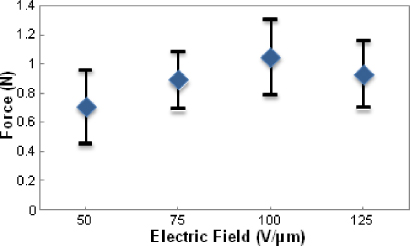
Figure 10. Average blocking force versus electric field for 8 actuators (blue diamond is the mean value and error bars indicate ± one standard deviation).
Download figure:
Standard image4.5. Frequency response and cycle life
Frequency response and cycle life of the devices are still in the testing phase, as more samples are needed to get sufficient data. The actuators have a much lower reliability when used in AC as compared to DC. At frequencies above 10 Hz, they tend to break down and burn within a few cycles, even at low voltages. It is believed that heat accumulation due to higher currents is causing this failure. One actuator survived 1000 cycles at 0.2 Hz and 700 V, however.
5. Braille cell design
Figure 11 shows a potential application of the actuators, a Braille cell using six actuators that is designed, fabricated, and tested. The cell dimensions are 40 mm × 12 mm × 70 mm. It is composed of three subparts:

Figure 11. Picture of the Braille cell with close-up views of the six pins spelling 'PSU'. A video showing the Braille display producing the letters 'P', 'S', and 'U' in sequence is provided in the supplementary data, available at stacks.iop.org/SMS/21/012001/mmedia.
Download figure:
Standard image
- A top section, which contains the ceramic pins that the user touches. The pins are 2.5 mm apart, and are connected to a metal plate that acts as a common ground. A magnet is glued on the bottom of each pin to contact the actuators.
- A central acrylic block, which is the housing for the actuators. Six holes of 2.2 mm diameter are drilled 2.5 mm apart. A separate hole is used to pass a ground wire to the top metal plate.
- A plastic base containing six set screws that contact the positive end of the actuators. Each screw can be used to compensate for differences in the initial lengths and displacement performance of the actuators.
The cell is integrated into a demonstration box, containing all the necessary electronics and batteries to activate the actuators at 550 V. A ribbon cable plugs into the bottom of the cell, connecting to the set screws and to the ground wire. Each pin can be individually turned on or off using switches mounted on the box. The device is currently being tested by the blind community.
6. Conclusion
A core-free P(VDF–CFE–TrFE) thin film rolled actuator can be fabricated using solution casting, stretching/annealing, electroding, laminating, rolling, bonding, and electrical contacting. The size of the actuator is scalable based on the width and length of available films and the number of layers. In this research, 2 mm diameter and 44 mm long actuators are fabricated and shown to provide up to 4% strain and 1 N of blocking force at 100 MV m−1. The lab-scale fabrication process has relatively low yield but significant improvements could be achieved by reducing hand fabrication and increasing automation. To prevent premature failure, the current (and hence bandwidth) of the actuators must be limited. A Braille cell using a 3 × 2 array of these actuators is successfully demonstrated. The actuators may also be suitable for a wide range of other applications, including artificial muscles, mechanisms, smart structures, and robotics.
Acknowledgments
The authors would like to thank L Gorny, M Lin and Y Ma for their help in understanding the behavior of PVDF materials and actuator fabrication.