

Abstract
In this paper, we review photonic methods and technologies that are promising for monitoring the ocean and atmosphere and have been implemented mainly in recent years at the Institute of Automation and Control Processes, Far Eastern Branch, Russian Academy of Sciences. We present results of lidar studies that have made it possible to understand key features of ocean – atmosphere interaction processes under continent – ocean transition conditions, which determine specific features of the atmospheric aerosol distribution, small gaseous components of the atmosphere and its optical characteristics. We consider methods and tools for combined optical and laser fluorescence monitoring of the ocean surface. Particular attention is paid to results of research on remote methods and tools for real-time laser-induced and laser fluorescence environmental monitoring of the ocean, including specialised fibre-optic probes and mobile underwater robotic systems. We present results of the development and investigation of highly sensitive, noise-proof fibre-optic hydro- and seismic/acoustic sensors for remote monitoring of the ocean and robotic systems for underwater laser protection of marine vessels, hydraulic structures and oceanographic instruments against the negative impact of biofouling.
Export citation and abstract BibTeX RIS
1. Introduction
Covering a large part of the Earth's surface, the world's ocean plays an exceptional role in ensuring life on the planet and determining the weather and climate. Interaction with the Earth's atmosphere and geological subsystem sets the thermal and dynamic regimes of the world's ocean, which determine the climate and weather in various regions of the globe and the development of dangerous natural phenomena, such as tsunamis, tropical cyclones, storm surges, etc. Solar energy absorption by the ocean determines processes underlying the circulation of mineral and organic substances and energy in natural ecosystems and the bioproductivity of living organisms that inhabit the world's ocean, primarily the photosynthetic activity of algae, which play a critical role in the oxygen and carbon dioxide balance in the atmosphere. The growth of the world population and advances in technologies for harvesting and utilising the world's ocean resources underlie an ever-increasing human impact on the ocean, which shows up as greenhouse gas emissions, pollution of coastal and marine waters and excessive withdrawal of biological resources.
The exploitation of the world's ocean resources requires not only novel exploration technologies but also techniques for assessing the effect of their withdrawal on the ocean environment. Analysis of modern methods and tools that are used to study and explore the world's ocean and the trends in their development demonstrates that wide use is made of various physicochemical principles in designing instruments and measurement technologies intended for periodic monitoring of the main hydrophysical and biogeochemical characteristics in near real time. One example is modern lidars, which allow one to assess optical and microphysical characteristics of optically active components of the atmosphere and the ocean [1 – 3]. Of particular interest in this context are photonic methods and tools, which have a wide range of unique characteristics [4]. Their advantages include electroneutrality, insensitivity to electromagnetic interference, good resistance to sea water attack, low weight and small dimensions, with the possibility of multiplexing dissimilar signals and assessing the state of living organisms directly in their habitat.
In this context, advances in photonic methods for resolving issues pertaining to the study and exploration of the ocean open up new possibilities of following the changes that occur in it, analysis of which makes it possible to detect, predict and prevent (or mitigate) emerging dangerous phenomena on a timely basis; conduct environmental monitoring of basins; and reveal changes and their causes on a timely basis.
In this paper, we review results of our multi-year research aimed at developing novel photonic methods, instruments and technologies promising for the investigation and exploration of the ocean and atmosphere.
2. Lidar monitoring of the atmosphere over the ocean
Intense attention paid to the properties of atmospheric aerosol is due to the key role it plays in determining the energy balance of the atmosphere and transporting atmospheric pollutants. To create a global aerosol map and construct regional and global aerosol models of the atmosphere, active use is made of network research methods taking advantage of solar photometry and multifrequency Raman lidars. The most extensive and detailed photometric studies are being conducted in the framework of the AERONET project, which coordinates operation of more than 1000 photometric stations [5]. The lack of information about the vertical distribution of properties of atmospheric aerosol is being effectively eliminated by lidar stations. In 2004, the CIS-LINET lidar network, comprising seven lidar stations in CIS countries, from Minsk to Vladivostok, began operation, to be eventually completed by the end of 2007 [6]. Researchers at the Institute of Automation and Control Processes (IACP), Far Eastern Branch, Russian Academy of Sciences, created a lidar system which included stationary and mobile lidars. It successfully functions today and allows one to monitor the height distribution of atmospheric aerosol and small gaseous atmosphere components, such as water vapour and ozone, in a wide range of heights, from the ground layer to the stratosphere.
Since 2009, the aerosol optical depth of the atmosphere and the spectral composition of direct solar radiation have been monitored in two regions of the Primorsky Krai using sun photometry techniques [7, 8]. Global atmospheric aerosol transport monitoring made it possible to assess the impact of the 2011 eruption of Grímsvötn volcano in Iceland [9]. The results showed that aerosol disturbance of the stratosphere was still noticeable half a year after the eruption and that volcanic aerosol transport in the stratosphere of the northern hemisphere was due to the subtropical jet stream [9]. Its presence in the atmosphere of the southern part of the Primorsky Krai determines to a significant degree the regional features of atmospheric aerosol and the optical characteristics of the atmosphere. The wintertime vertical ozone distribution was found to have a characteristic structure (with two peaks) due to vertical air mass transport in the jet stream region and a double tropopause (Fig. 1), which underlies a mechanism of air mass exchange between the troposphere and stratosphere and the possibility of dust aerosol capture and long-range transport [10 – 12].
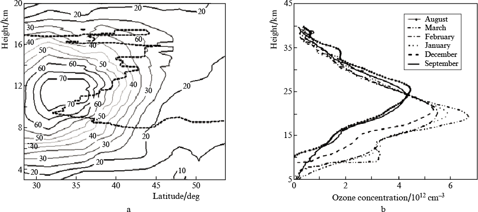
Figure 1. (a) Height – latitude section of the wind field of the subtropical jet in February 2008 and position of the tropopause (dashed line) according to data from 13 high-altitude sensing stations; (b) average vertical ozone distribution profiles in different months from 2007 to 2009.
Download figure:
Standard imageIntegrated studies of the optical characteristics of the atmosphere during the spring monsoonal rainfall period allowed the main regional features of atmospheric aerosol in the southern part of the Primorsky Krai to be pinpointed [7, 8, 13]. Analysis results demonstrate that the atmosphere in this region in spring is distinctive in that the aerosol optical depth there is twice that in other (marine and continental) mid-latitude regions. The large aerosol optical depth is due to continental aerosol outflow, which originates predominantly from arid (Gobi and Takla Makan Deserts) and industrial regions in the adjacent territories of China [8]. In this period, atmospheric aerosol loading over the Sea of Japan is comparable to aerosol loading in the trade wind zone of the Atlantic and the Sea of Darkness. Vertical aerosol – molecular scattering profiles (Fig. 2) [7] clearly show two increased light scattering regions, which characterise the aerosol height distribution: a broad subtropopause layer with a statistical maximum at a height of 8 km and a layer in the region of the planetary boundary layer (at a height of ∼2 km). The variability of the subtropopause layer reflects to a significant degree dust activity and aerosol transport (with a delay for about three days) from arid regions in China and Mongolia. As a rule, dust aerosol deposition in seawater is accompanied by subsequent algal bloom outbreaks [14], because deposited particles contain iron oxide nanoparticles and the nutritive base of algae in the form of mineral fertilizers. It is this factor which often leads to environmental disasters in the ocean, whose time and place can now be predicted using lidar measurement results.
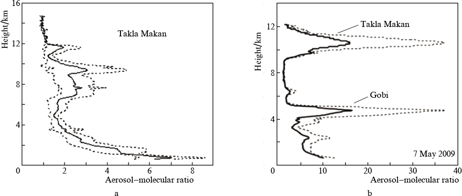
Figure 2. Average (solid lines) and standard (±) deviation (dashed lines) of the vertical aerosol – molecular ratio profiles of aerosol sources assessed using inverse trajectory analysis: (a) Takla Makan Desert and (b) arid regions of the Gobi and Takla Makan Deserts.
Download figure:
Standard imageMonitoring the state of the atmosphere is directly related to global warming issues and the state of the Earth's ozone layer. In connection with this, there is now a growing need for an in-depth study of the interrelation between stratospheric and tropospheric processes and the relation between stratospheric processes and weather anomalies. For this purpose, it is necessary to perform systematic prolonged measurements and determine statistical characteristics of the measured parameters of the stratosphere etc. At present, remote monitoring of atmospheric processes is conducted predominantly by passive methods, and observation globality is ensured by placing observation systems in space (MODIS, POLDER, OMI and other satellites) [15]. Satellite measurements allow one to estimate the aerosol optical depth in several spectral channels. Coupled with observations by a ground-based photometer network, this allows one to gain information about global aerosol transport and main aerosol parameters. Such measurements, however, provide only height-integrated characteristics, whereas the effect of aerosol on the radiant flux is associated to a significant degree with its height distribution. Information about the height distribution of aerosol can only be gained using laser remote sensing of the atmosphere. The lidar station created at IACP carries out a systematic study of characteristics of the atmosphere over the ocean and successfully operates in cooperation with the Center for Satellite Monitoring, supplementing results provided by space-based tools.
3. Fluorescence lidar and optical polarimetric monitoring of the sea surface
The coastal and shelf waters of the world's ocean account for more than 80 % of the marine bioresources. The key elements ensuring life activities of ecosystems in near-shore water areas are dynamic processes serving for water purification and ventilation. Characterised by high spatial and temporal variability, these processes cannot be effectively monitored without taking advantage of remote sensing methods. One such method is photogrammetry, which is used for processing video and radar images of the sea surface [16]. Dynamic processes, such as surface flows, frontal and upwelling zones, internal waves and Langmuir circulation, show up on the sea surface as 'glazed' zones (slicks): areas with suppressed small-scale wind waves, which allows for their visualisation. Another issue that can be addressed via joint use of fluorescence lidar and video recording is the monitoring of oil spills and sea surface contamination with organic films. Such systems were recommended by the International Maritime Organisation (IMO) for use in real-time oil spill monitoring systems [17]. Note that a video system is capable of providing information about the coordinates and extent of organic film, and a lidar offers the possibility of determining its composition from its fluorescence spectrum. A small-size fluorescence lidar with a synchronous recording system, designed at IACP, allows for real-time sensing of the sea surface from a small motor boat at any time of the day.
For recording dynamic characteristics of the sea surface, mapping organic films on the sea surface and tracking marine traffic, we designed a scanning polarimetric video system capable of monitoring a water area of 7 km radius in an angular sector of 270° [18 – 20]. Mounted on a pole onshore or on a quadcopter, the polarimetric video system allows one to easily follow the dynamics of small sea vortices encountered in coastal waters and small bays. Spiral vortice arms have a nonuniform brightness structure, which can be used to assess the rotation rate field in the vortice. Figure 3 shows images of two ocean vortices (an anticyclonic vortice at left and a cyclonic one at right) the most active in Vityaz Bay in autumn. According to results of experimental studies, the polarimetric video system can also be successfully used to evaluate the surface wind speed, ensuring measurement accuracy of 10 % or better at wind speeds in the range 3 – 7 m s−1 [19, 21].
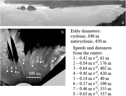
Figure 3. (a) Panoramic and (b) topographic images of two ocean vortices observed in Vityaz Bay with the use of the polarimetric video system.
Download figure:
Standard imageIt is known that one mechanism of vertical seawater mixing and horizontal seawater momentum and energy transport is internal gravity waves (IGWs) [22]. As a rule, IGWs are generated in the region of the largest density and temperature gradients in a body of water and can be detected in optical images of the sea surface. The high temporal and spatial resolution of the polarimetric video system designed by us makes it possible to examine in detail and analyse IGW-related processes, such as the transformation of a single soliton propagating in the ocean environment into an IGW train in shallow water or interaction of an IGW train with a small ocean vortice and energy transfer to it [23].
Water surface monitoring with the use of polarimetric video systems is an essential supplement to proven radar methods of oil spill detection. In connection with this, the problem of reliably detecting and identifying slicks and attributing them to oil films is currently central to many research groups dealing with remote sensing of the sea surface [24 – 27]. We constructed a model for optical contrast between an image produced by a thin film in a slick and an image of a rough sea surface outside it [26, 27]. Based on this model, we estimated the contrast of a slick on the sea surface in relation to the wind speed and direction, taking into account sea surface illumination conditions. The viability of the model was illustrated by a series of experiments in which slicks were imaged from a quadcopter (Fig. 4a) having an optical polarimeter mounted on its suspension. Portions of a series of images of an oil slick on the sea surface (Figs 4b, 4c) demonstrate sharp changes in contrast with increasing observation zenith angle.
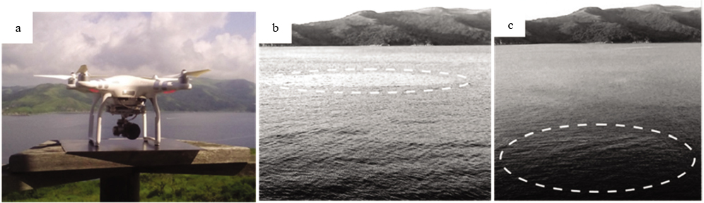
Figure 4. Quadcopter with a polarimeter on board (a) and images of slicks at vertical observation angles of 86° (b) and 76° (c).
Download figure:
Standard imageExperimental studies clearly demonstrated the possibility of detecting oil films with the use of polarised light images of the sea surface and determining the composition of the films from changes in the fluorescence spectrum using a fluorescence lidar in combination with the polarisation system.
4. Remote (probe) fibre-optic laser fluorescence environmental monitoring of the ocean
The monitoring of the state of water areas requires gaining real-time information long before visible signs of pollution considerably exceeding maximum allowable concentrations (MACs) emerge. In recent years, in the framework of the environmental monitoring of the state of water areas, intensive research effort has been concentrated on living organisms, in particular on unicellar algae (phytoplankton), which offer enhanced sensitivity to the impact of adverse environmental factors [28]. As a rule, specific manifestations of these factors are related to their effect on certain molecular cell structures. Phytoplankton exhibit high sensitivity to a rather wide range of water pollutants, including metal ions, herbicides, pesticides, cyanides, methyl parathion (MPT), N'-(3,4-dichlorophenyl)-N,N-dimethylurea (DCMU) and surfactants [29 – 31].
One key property of unicellular algae is fluorescence of cell pigments under laser illumination: laser-induced fluorescence (LIF). LIF measurement methods offer high sensitivity and high speed, with the possibility of analysing nonlinear fluorescence signal parameters [32, 33]. Moreover, the fluorescence response of microalgal cells depends on not only the nature and concentration of the culture but also the conditions under which they are during measurements: from the temperature and illuminance to the presence of organic and inorganic substances dissolved in the water [34]. For this reason, LIF is currently one of the main methods used in techniques and instruments for probing the state of phytoplankton and measuring the concentration of microalgae directly in their habitat, without damaging cells [35].
We designed a unique sensing fibre-optic fluorometer with a submersible module, which allows for real-time spectral measurements in a wide wavelength range (from the violet to the near IR) at depths of up to 100 m (Fig. 5) [36], as distinct from most other instruments. The fluorometer comprises an above-water and a submersible part, connected to each other by a fibre-optic SPC cable. The above-water part includes an emitter/receiver unit and personal computer, which ensures control over studies and data processing. The fluorometer is intended for real-time monitoring of the spatial distribution of phytoplankton, chlorophyll a and organic and mineral substances dissolved in seawater. As a rule, the fluorometer is incorporated into a ship's mobile laser system, which is a multifunctional stage for environmental monitoring, prediction of the productivity of sea zones, a search for hydrocarbon deposits and seafloor methane activity detection.
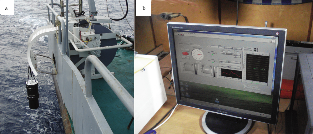
Figure 5. (a) Ship's mobile laser system with a submersible fibre-optic module and (b) operator's workplace.
Download figure:
Standard imageThe LIF spectrum is determined by the pigments present in microalgal cells and ambient conditions. LIF intensity depends on photochemical reactions occurring in reaction centres, especially in complexes of the second photosystem (PSII), which is not only responsible for light absorption and oxygen generation but also determines a major part of the fluorescence spectrum of phytoplankton. The spectral density of fluorescence of natural phytoplankton is a weighted average quantity dependent on the relative amount of PSII complexes, incident light intensity and the state of chlorophyll a in the complexes [37]. Because of this, LIF allows one to reveal damage to phytoplankton under the effect of anthropogenic and natural pollution long before this shows up as a decrease in their number.
Raising the temperature leads to nonphotochemical quenching of LIF for chlorophyll a, which we should take into account in determining its concentration [38, 39]. Temperature-dependent fluorescence results for more than 20 microalgae species made it possible to propose a new method for their recognition [40]. To this end, we designed a special submersible fibre-optic fluorescence probe containing a flow chamber in which water was heated, cooled and thermostated in a wide temperature range [41]. The use of the probe opened up the possibility of real-time assessment of the concentration and biodiversity of phytoplankton community in places and at depths of greatest interest for evaluating and predicting the environmental state of water areas.
At present, there are several main approaches to designing biosensors based on natural phytoplankton LIF measurements. As shown in extensive studies, a promising direction is the development of biosensors based on a colony of immobilised microalgal cells placed in a porous water-permeable medium [42 – 46]. In such a case, a small pore size prevents cell motion and fission, which makes it possible to impart spatial and temporal stability to the cells, ensure convenient storage of them and avoid using liquid solutions.
As shown by Nikolskaya et al. [45], biosensors based on immobilised microalgal cells ensure sensitivity at a level of tenths of the MAC of dissolved chemical elements. This stimulated studies concerned with a species search for microalgae cultures and matrix designs for their immobilisation that will make it possible to detect particular chemical substances in a medium with high accuracy. Figure 6 presents experimental data for immobilised Nannochloris maculata and Tisochrysis lutea microalgae cultures [47] placed in a porous silicate matrix [48] in the presence of copper, zinc and iron(II) salt solutions. The data illustrate the time evolution of the fluorescence intensity of chlorophyll a in the Nannochloris maculata culture at a wavelength of 680 nm and the MACs of copper, zinc and iron(II) salts in solution and in the Tisochrysis lutea culture at a wavelength of 685 nm at different copper ion concentrations. The present results confirm that the microalgae cultures under consideration have high sensitivity to and high reactivity with pollution of their habitat. This allows these microalgae to be used as natural sensors for monitoring the ecological state of the environment.
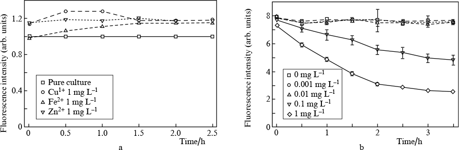
Figure 6. (a) Effect of the MACs of copper, iron and zinc salts on the fluorescence intensity of Nannochloris maculata chlorophyll and (b) 685-nm fluorescence intensity of Tisochrysis lutea (27.25 × 10⁴ cells L−1) at different copper ion concentrations.
Download figure:
Standard image5. Automated laser-induced spectroscopy monitoring of the chemical composition of the ocean environment
To address issues pertaining to the exploration of the continental shelf, monitoring of the ocean, seawater bioproductivity assessment and environmental monitoring of sea and coastal area pollution, it is necessary not only to use standard bio- and geochemical methods but also to develop rapid methods for remote elemental analysis of liquid media without special sample preparation procedures. Such rapid methods should meet the following requirements: a wide range of elemental analytes, high measurement speed and reproducibility and high sensitivity. Laser-induced breakdown spectroscopy (LIBS) is an effective tool for qualitative and quantitative in situ analyses of substances and meets the main requirements among those above [48]. As shown previously [49, 50], LIBS is a promising method for geochemical, environmental, aquatic and underwater sensing. One drawback to LIBS in analysis of liquid media is its relatively low sensitivity, so a great deal of attention is paid to improving its sensitivity [48] because, in the case of plasma generation by nanosecond pulses, the limit of detection (LOD) for many chemical elements is at a level of a few ppm. As a rule, to improve the sensitivity and detection limit of LIBS, time gating is used, a technique in which the optimal time delay td between signal recording and the laser pulse and the optimal signal acquisition time tg depend on the chemical element to be determined and the way in which plasma is generated on the sample surface [48 – 50].
According to results of our studies, one way to improve the sensitivity of LIBS is to use femtosecond laser pulses for generating an optical breakdown plasma on the sample surface (femtosecond LIBS) (FLIBS) [51 – 53]. The key features of FLIBS are the relatively low detection limits for elements in aqueous solutions and the possibility of determining the elemental composition of the surface of liquids at pulse repetition rates (PRRs) of up to 1 kHz, which is very important for real-time monitoring of water areas [53]. The better sensitivity of FLIBS is due in particular to the fact that the mechanical and thermodynamic parameters of laser breakdown plasmas generated by nanosecond and femtosecond pulses differ drastically [54]. In the case of atoms and ions in a femtosecond plasma generated on the surface of a liquid, a significant role is played by electron impact pumping of excited states from the ground state [55]. This fact stems from the low plasma temperature and low electron density (in comparison with a plasma generated by nanosecond pulses), which leads to low intensity of the continuous spectrum [51, 53]. Moreover, femtosecond pulses change time dependences of intensities of the continuous and line spectra of the plasma [56], a smaller number of liquid droplets are ejected onto the focusing optics, and there are no lines of nitrogen or oxygen ions in the optical spectra of the plasma [51, 54].
We determined the optimal time delay td for recording time-resolved FLIBS spectra for nine chemical elements (Table 1) and calculated detection limits for a number of chemical elements at pulse energies E = 1 and 7 mJ [52, 53]. Our results demonstrate that (in addition to time gating) the intensity of the line spectrum in FLIBS can be raised by increasing the power density incident on the sample surface via better laser beam focusing or by increasing the pulse energy [53]. It is worth noting that it is preferable to raise the power density in the focal spot by reducing the focal length of the lens for effective excitation of atomic emission lines of chemical elements and by increasing the pulse energy if more remote measurements are necessary [52]. Assessing the effect of the laser pulse repetition rate (in the range 50 – 1000 Hz) on the detection limits of FLIBS for Mg, Mn, Pb and Sr in water indicates that, to maximise the emission line excitation efficiency, the PRR should be near 166 Hz [56].
Table 1. Detection limits of FLIBS for chemical elements in aqueous solutions.
| Chemical element | λ/nm | E/mJ | td/s | PRR/kHz | LOD/mg L−1 |
|---|---|---|---|---|---|
| Al I | 396.1 | 1 | 150 | 1 | 0.19 |
| Ba II | 455.4 | 1 | 72 | 0.1 | 0.08 |
| Ca II | 393.3 | 1 | 55 | 0.5 | 0.01 |
| Cu I | 324.7 | 1 | 92 | 0.1 | 0.78 |
| K I | 766.5 | 1 | 180 | 1 | 0.006 |
| Mg I | 285.2 | 1 | 120 | 1 | 1 |
| Na I | 588.9 | 1 | 210 | 1 | 0.0009 |
| Zn I | 213.8 | 1 | 57 | 1 | 2.5 |
| Fe I | 373.7 | 1 | 160 | 1 | 3.4 |
| Fe I | 371.99 | 7 | 160 | 0.05 | 2.6 |
| Fe I | 377.99 | 7 | 190 | 0.05 | 3.0 |
It follows from the data in Table 1 that, in aqueous solutions, FLIBS ensures detection limits from 10−6 to 10−3 g L−1, depending on the nature of the chemical element to be determined [57]. The use of ultrashort laser pulses has already made it possible to produce compact millijoule pulse energy systems capable of operating under ship conditions.
At present, the exploration of the ocean and, especially, of its continental shelf is becoming more and more important. In conjunction with the development of underwater laser technologies, this stimulates the fabrication of rapid chemical analysis apparatus to be installed in remotely operated vehicles (ROVs). For this purpose, we designed a mobile underwater robotic system for determining the chemical composition of water in real time with the use of a laser-induced breakdown spectrometer and survey ROV (Fig. 7), which were full-scale tested between July and October 2018 [58].

Figure 7. Photographs of the underwater robotic system for determining the chemical composition of water in real time during full-scale tests in October 2018.
Download figure:
Standard imageThe system comprises two main units: a remotely operated underwater vehicle (with the following main characteristics: submergence depth, up to 150 m; maximum submergence speed, 1 m s−1; maximum motion speed, 2 m s−1) and a laser-induced breakdown spectrometer module with an excitation source (diode-pumped Nd : YAG laser) and microcomputer. The two main units and a control panel are linked through Ethernet. Spectroscopic data are processed in the MATLAB environment. In designing the mobile laser-induced breakdown spectrometer, we also took into account that a plasma in a gaseous environment (on the soil or water surface) has a higher temperature than does a laser plasma generated in a body of water and allows a larger number of chemical elements to be determined with lower detection limits [48]. Because of this, the spectrometer design includes a gas (air) delivery line for producing a gaseous atmosphere during analyses.
The mobile underwater robotic measuring system does not require any special type of ship and allows one to operate directly on board a research vessel, on beach or a pier, up to 400 m from the operator panel [58, 59].
6. Fibre-optic sensors for hydroacoustic monitoring of shallow water
Resolving problems of assessing the underwater situation, probing underwater objects and monitoring the ocean and underwater communications is inextricably connected with the production of effective tools for reliably recording hydroacoustic signals. One nontrivial issue in hydroacoustic monitoring is the ability to detect acoustic signals under shallow water conditions. Distinctive features of this situation include multiple interference of acoustic waves multiply reflected from the bottom and the surface of water, whose distribution varies over time as a consequence of sea surface undulation, giving rise to acoustic signal fluctuations where the signal is received [60].
Most modern hydrophones utilise electrical transducers [61, 62], whose drawbacks include sensitivity to electromagnetic interference and the need for long electrical cables to transmit weak signals over considerable distances. The ability to resolve these problems directly depends on the development of non-electrical analogues of acoustic signal sensors, primarily, sensors based on fibre-optic components [61]. The use of highly sensitive interferometric principles of measurements in designing fibre-optic hydrophones offers the potential of detecting ultraweak acoustic signals [62]. At the same time, because of their high sensitivity, interferometric measuring systems are influenced by uncontrolled external factors (random mechanical influences, temperature or pressure drift and others), which in practice nullifies all their advantages. The use of electronic systems for stabilising working characteristics of fibre-optic interferometric hydrophones [63, 64] significantly complicates the measuring system, leads to a disproportionate increase in its size and degrades its reliability, mobility and self-containment.
One possible alternative to the classic homodyne optical interferometer with an active stabilisation system is an adaptive holographic interferometer, in which light beams are combined with the use of a dynamic hologram inscribed into a photorefractive crystal [65 – 68]. The inverse of the time taken to inscribe a dynamic hologram is referred to as the cutoff frequency, f0. Since the dynamic hologram is constantly rewritten, the operating point of the interferometer is kept in the linear portion of its working characteristic, corresponding to its highest sensitivity, and the interferometer adapts to all influences (noises) whose frequency is below f0 and stably records all influences whose frequency is above f0. As a consequence, the adaptive laser hydrophone (ALH) becomes capable of stably detecting weak acoustic signals under real conditions in the presence of considerable uncontrolled environmental influences, thereby ensuring stable detection of hydroacoustic signals under shallow water conditions.
We designed ALHs with membrane and coil transducers of acoustic pressure [68 – 71]. The sensing element of the membrane transducer is a mirror-coated metallic membrane embedded in the hydrophone housing. Its oscillations caused by the field of an acoustic wave modulate the phase of a reflected signal wave. In the coil transducer, the optical fibre of the signal arm of an interferometer is wound onto an elastic cylindrical frame from extruded polystyrene foam. An acoustic field changes the dimensions of the elastic cylinder, leading to changes in the length of the fibre wound onto it, thus modulating the phase of the laser light propagating in it.
In the case of an ALH based on a dynamic hologram inscribed into a CdTe crystal, the inscription time was ∼5 ms (f0 = 200 Hz). At a daily temperature difference of ±10 °C and in the presence of random external mechanical influences, this made it possible to detect weak acoustic signals with frequencies above 200 Hz. Moreover, fluctuations of the signal being detected were within 1 % over 24 h of continuous operation [66]. Both the membrane and coil ALHs were shown to have sensitivity in a frequency band above 100 kHz: the sensitivity of the membrane ALH at a frequency of 10.5 Hz is 6.2 mrad Pa−1 [69] and that of the coil ALH at a frequency of 6.5 kHz is 4.1 mrad Pa−1 [70].
Figure 8a shows a photograph of a mobile version of the fibre-optic adaptive laser hydrophone (MALH) with a coil-type sensing element. The MALH was tested in the Vladivostok water area (Golden Horn Bay, Eastern Bosphorus Strait) at an ambient temperature of –3 °C, water temperature of 1 °C, wind speed of 13 m s−1, moderate undulation of the sea surface and high harbour noise produced by ship traffic. The MALH and all testing equipment were located on the quay wall of the sea pier (Fig. 8b) [71]. In the water area, a piezoelectric emitter produced a field of a hydroacoustic wave at a frequency of 5 kHz. Figure 9 shows the spectrum of the hydroacoustic test signal detected with the use of the MALH. In spite of the considerable low-frequency noise in the water area, the MALH ensured stable detection of the hydroacoustic signal at a working frequency of 5 kHz. Over a 45-min period, the amplitude of the continuous hydroacoustic signal was constant to within 5% and the signal-to-noise ratio (SNR) was 26 dB.
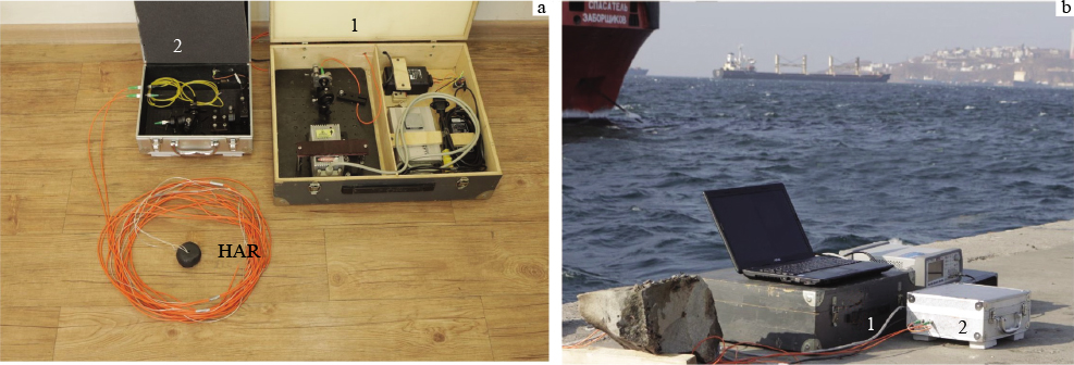
Figure 8. (a) Appearance of the MALH: (1) laser module; (2) interferometric module; HAR = coil-type fibre-optic hydroacoustic transducer; (b) photograph of the full-scale MALH test stage at the quay wall in the water area of Golden Horn Bay.
Download figure:
Standard image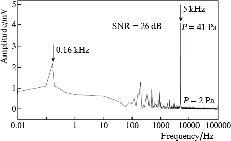
Figure 9. Spectrum of the MALH output signal for detection of a hydroacoustic test signal under typical sea area conditions (P is pressure).
Download figure:
Standard imageThus, the fibre-optic laser hydrophone based on an adaptive holographic interferometer is capable of ensuring stable detection of weak hydroacoustic signals under real conditions characterised by destabilising factors such as drift of the ambient temperature and pressure, flows, undulation (in particular, under shallow water conditions) and industrial noise due to the proximity of port infrastructure, sea ship traffic etc.
7. Seismic/acoustic fibre-optic sensors for low-frequency monitoring of the ocean
At present, there is a stable trend towards a transition to the low-frequency (LF) and infra-low-frequency (ILF) ranges of operation of systems for the acoustic monitoring of the ocean. The reason for this is that acoustic signals in the range from tens to hundreds of hertz are the most effective tool for diagnosing and monitoring the ocean on a large scale, from tens to thousands of kilometres. The ability of LF acoustic waves to travel long distances in the ocean environment is already in wide use for a variety of military and civilian applications, which include, for example, detection of underwater targets, classification and localisation of objects, geological mapping and bottom depth profiling, topography of the ocean, acoustic holography, seismic modelling and measurement, biological noise measurement and tsunami detection [72].
In this context, there is currently an immense need for fast, compact, reliable, cheap and energy-saving sensors for LF and ILF (seismic/acoustic) acoustic monitoring of the ocean [73, 74]. Since conventional piezoelectric seismic sensors have insufficient sensitivity at frequencies below 10 Hz, and electrodynamic seismic receivers are difficult to apply in sea seismo-acoustics [75], fibre-optic sensor systems capable of resolving the issue in question have been used increasingly in the past few decades in monitoring of the ocean, underwater perimeter intrusion detection systems, hydroacoustic communications etc. [76 – 78].
In designing ILF fibre-optic seismic receivers, of most interest is the rather simple configuration of the Mach – Zehnder interferometer. One of its measuring arms includes a sensing element with an inert mass attached to it, which converts surface oscillations into changes in fibre length and the associated changes in the phase of light propagating through the fibre [79].
Since a two-arm fibre-optic Mach – Zehnder interferometer offers the possibility of measuring the phase change of optical radiation to a level of 10−7 rad Hz−1/2 [80], at a scale factor S = 0.1 rad m−1 s2 this allows a fibre-optic seismic receiver to have a threshold sensitivity of 10−6 m s−2 Hz1/2.
The most serious problem with ILF fibre-optic Mach –Zehnder interferometers is the drift of their operating point, due to laser source wavelength instability and uncontrolled variations in ambient temperature. To obviate this problem, use is made of various phase demodulation methods, among which active and passive signal homodyning techniques are worth noting [81, 82]. In the case of active homodyning, the position of the operating point in the middle of the linear portion of the transfer characteristic of the interferometer (quadrature operation) is stabilised by placing an additional piezoceramic phase modulator, which compensates for operating point drift, in the reference arm [83]. This demodulation method allows quadrature operation of the interferometer to be maintained at operating point drift rates of up to 2000 rad s−1 [84].
The inset in Fig. 10 shows a photograph of a Mach – Zehnder interferometer-based fibre-optic accelerometer designed at IACP, which uses active homodyning [82]. The design of the multiturn sensing element (MSE) of the accelerometer comprises two fibre-wound cylinders. One cylinder is rigidly connected to the accelerometer housing and the other serves as an inert mass. The resonance frequency of the MSE is determined by the stiffness of the fibre, the number of turns and the inert mass chosen [79]. Figure 10 (curve 1 ) shows the frequency response curve of the fibre-optic accelerometer whose signal arm contains ten turns of single-mode fibre with a stiffness of 16.3 kN m−1 and an attached inert mass of 1 kg. The low-frequency scale factor of the MSE of the accelerometer is S = 500 rad m−1 s2. At an intrinsic noise level of 100 μV in the measuring system, this ensures a threshold sensitivity of ∼10−7 m s−2 at a frequency of 20 Hz.

Figure 10. Photograph of a multiturn fibre-optic interferometric accelerometer (inset) and frequency response curves of accelerometers with (1 ) active and ( 2 ) passive homodyning.
Download figure:
Standard imageFigure 11 shows time dependences of signals for a magnitude 4.7 earthquake that occurred on the 2nd of December 2019 at the coast of Kamchatka at a depth of 64 km. The measurements were performed at a frequency of 7 Hz using a standard CMG-5T force balance accelerometer (Guralp Systems Ltd, the United Kingdom) and the fibre-optic accelerometer shown in Fig. 10. As seen from Fig. 11, the sensitivity of the fibre-optic accelerometer is almost twice that of standard force balance accelerometers widely used in geophysical measurements, suggesting that it is potentially attractive for geophysical applications.

Figure 11. 7-Hz oscilloscope traces of a seismic event detected by (a) a Guralp force balance accelerometer and (b) the fibre-optic accelerometer produced at IACP.
Download figure:
Standard imageIt is also worth noting that, even though active signal homodyning in fibre-optic accelerometers makes them difficult to use in underwater applications, such accelerometers can be successfully used for seismic/acoustic monitoring of the ocean in coastal areas. This possibility was experimentally demonstrated by detecting LF acoustic signals produced during sea ship traffic more than 10 km from the seashore, where a fibre-optic accelerometer was mounted [85, 86].
Passive homodyning of fibre-optic interferometer signals makes it possible not only to stabilise the working characteristics of the interferometer but also to do without additional electronic components [80]. Researchers at IACP designed a fibre-optic accelerometer in which the optical scheme of passive homodyning is based on a 3 × 3 fibre coupler placed at the output of a fibre-optic Mach – Zehnder interferometer [87]. Figure 10 (curve 2 ) shows the frequency response curve (FRC) of a fibre-optic accelerometer based on a Mach –Zehnder interferometer with passive homodyning. In the linear portion of its FRC, in the frequency range 1 – 30 Hz, the sensitivity of the accelerometer is 480 rad m−1 s2, approaching that of a fibre-optic accelerometer with active operating point stabilisation. One important advantage of the fibre-optic interferometer configuration with passive signal homodyning is that there is no need for a phase modulator, electrical feedback circuit or additional current source. These benefits open up wide possibilities of utilising such fibre-optic interferometers for producing fibre-optic seismic receivers intended for operation in water.
8. Robotic underwater laser removal of biofouling from objects used in marine environments
Biofouling is a natural process in which a variety of organisms multiply on the surface of ships' hulls, hydraulic structures and measuring instruments situated in water. At present, more than 4000 organisms are known to be biofoulers [88]. Seashells and algae accumulated below a ship's water line lead to increased drag, which can require up to a 40 % increase in fuel. A large weight of biofouling can lead to emergencies in hydraulic structures and disturb the operation of oceanographic sensors intended for continuous mechanical stress, temperature, acoustic sensitivity, dissolved oxygen, turbidity, pH, fluorescence and other measurements [89].
The battle with biofouling is extremely expensive: billions of dollars have to be spent annually throughout the world to prevent it. At present, there are three main approaches to antifouling: (1) the use of specialised paints containing biocides capable of killing biofoulers, (2) the use of self-polishing silicone-based coatings that impede attachment of biofoulers to surfaces and (3) mechanical underwater cleaning. Since all these methods have serious drawbacks, a search for an effective and environmentally clean and safe technology for biofouling removal from the surface of vessels, hydraulic structures and oceanographic sensor housings remains a topical issue.
Fibre lasers play an important role in processing various materials for use in mechanical engineering and industry [90]. One widely employed fibre laser-based technology is surface cleaning. This technology compares favourably with conventional methods in that it requires no consumables, can be operated remotely and is environmentally friendly. Moreover, there are no wearable parts and the result and degree of cleaning are easy to assess [91]. It is these advantages which gave impetus to our work directed at developing a process for underwater laser removal of biofouling from surfaces of objects using low and intermediate laser beam powers. Basic to the laser cleaning process is evaporation or ablation of organic, polymer or oxide films from the surface of materials under the effect of cw or pulsed laser radiation [91].
Marine biofouling involves a great diversity of organisms capable of firmly attaching to solid surfaces situated under water [92]. The biofouling process usually comprises five main stages, from the adsorption of organic and inorganic macromolecules immediately after immersion of an object in water to the attachment of larger marine invertebrates, such as seashells, mussels, and macroalgae [93].
We designed a process for robotic underwater laser removal of biofouling from the surface of objects in an air flow produced directly in water. To this end, we carried out a series of studies aimed at gaining insight into interaction of laser light with different types of biofoulers, developing a specialised emitter design and optimising the laser cleaning procedure [94 – 96]. As light sources, we used cw ytterbium-doped fibre lasers emitting at a wavelength of 1.06 μm, with an output power tunable in the range 100 – 1000 W.
We carried out full-scale experiments directed at identifying biofouling species, determining the biofouling rate on the surface of painted and unpainted steel and fibreglass plates and assessing the plate cleaning quality ensured by mechanical and laser processing. Our results on the taxonomic composition of biofouler communities showed that fouling occurred even during the first month after the plates were immersed in seawater. Note that, whereas biofouling was almost indiscernible during the first month, they reached a considerable size, 5 – 8 mm, after 2 – 3 months (Fig. 12). The associated surface roughness had a negative effect on the hydrodynamic characteristics of the objects.

Figure 12. (Colour online) Photographs of (a) an unpainted and (b) a painted steel plate and (c) a fibreglass plate after two months of immersion in water of the Sea of Japan.
Download figure:
Standard imageOur experimental data showed that the struggle against fouling of objects with the use of laser light was rather effective in the first to fourth stages of fouling, as illustrated by the photographs presented in Fig. 13. In these stages of fouling, a relatively low laser beam power, 50 – 300 W, was sufficient for complete surface cleaning. In this case, the low laser beam power, high surface processing rate (∼15 cm2 s−1) and the possibility for the paintwork to be retained warrant economically favourable solutions in developing an underwater biofouling removal technology.
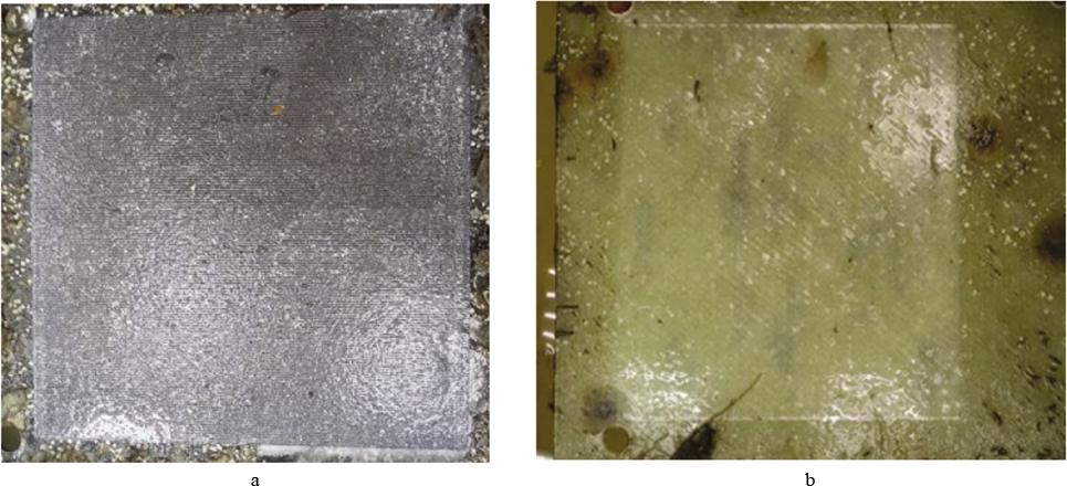
Figure 13. (Colour online) Photographs of (a) an unpainted steel plate and (b) a fibreglass plate after biofouling removal in water by a 100-W laser beam.
Download figure:
Standard imageAs shown in a comparative study of mechanical and laser processing techniques for biofouling removal, conventional mechanical cleaning usually disturbs paintwork, removing only the roughest overgrowths and leaving a nutrient (in the form of a thin film) suitable for the attachment and growth of new biofoulers. Underwater laser cleaning ensures much better results, ensuring essentially complete surface cleaning. In this case, however, a critical parameter is the time interval between two successive cleaning events. If an object has been immersed in water for a long time, i.e. in the case of a later, fifth, stage of fouling, which involves the formation of calcified houses of barnacles and worms, the laser beam power needed for surface cleaning rises almost exponentially (as a function of the biofouler size) and can reach 1000 W.
Eventually, our results suggest that, to optimise the rate of underwater laser removal of biofouling, it is reasonable to perform cleaning every one or two months. At this duration of immersion in seawater, the calcified fouling structures the most difficult to remove from the surface of objects only begin to form. Accordingly, even a relatively low laser beam power ensures their complete removal, without damage to the paintwork.
Our results regarding the underwater laser cleaning process were used as a basis in designing a unique robotic laser system comprising a remotely controlled underwater robot and an ytterbium-doped fibre laser (Fig. 14), which allowed for underwater biofouling removal from ships' hulls and horizontally and vertically oriented technical and hydraulic engineering objects at a rate of 5.4 m2 h−1 at depths of up to 10 m [97]. The system is equipped with video surveillance systems which make it possible to remotely assess cleaning quality and the surface condition of the object. Since the only most effective approach to struggling against biofoulers is to physically remove them, the robotic underwater laser cleaning system created by us can become an effective tool for protecting underwater monitoring instruments and systems against unwanted biofouling effects.
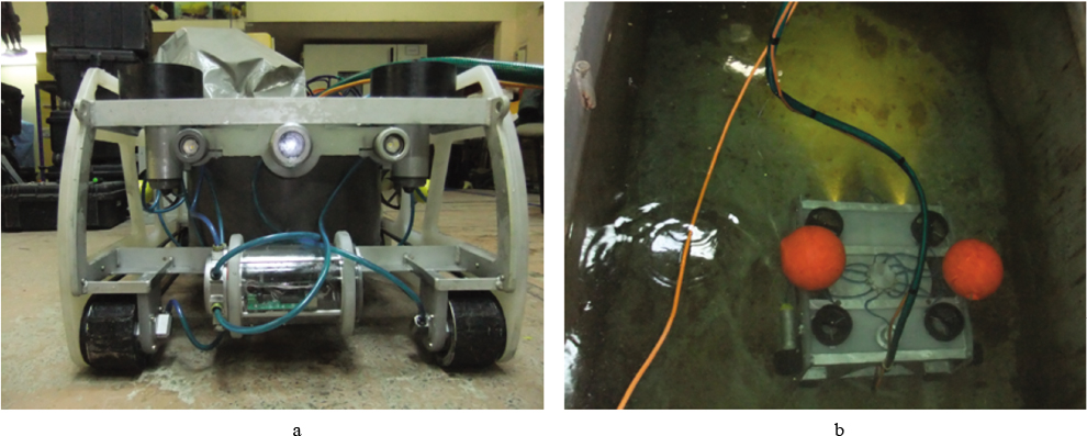
Figure 14. Photographs of (a) a robotic system for underwater laser biofouling removal and (b) a test of the system in a pool.
Download figure:
Standard image9. Conclusions
The ocean plays an immense role in the life of mankind, but our knowledge of it is limited. The monitoring of it is of particular importance at the present stage, when the world's ocean and coastal and marine ecosystems are undergoing significant changes as a result of the growing greenhouse gas emissions, pollution of coastal zones, excessive catch of fish and other hydrobionts, development of coastal areas and population growth. In the effort to understand and utilise this unique world, researchers of the ocean encounter many serious problems. It is this which stimulates a search for novel methods and systems for monitoring the ocean, which should help investigate and explore this object important for mankind. The use of photonics in designing tools for monitoring the ocean opens up new possibilities for making effective means of gaining the most detailed information about the world's ocean and its interaction with its environment. The research results presented in this review summarise the multi-year work of scientists and engineers at IACP, aimed at creating effective tools for lidar and optical monitoring of the atmosphere and ocean surface, robotic laser methods for determining the chemical composition of water and bottom soil, laser-induced fluorescence tools for the environmental monitoring of the ocean and developing highly sensitive, noise-proof fibre-optic hydro- and seismic/acoustic instruments for remote monitoring of the ocean and robotic systems for protecting underwater monitoring devices against biofouling. The main purpose of that research was to ensure the possibility of obtaining qualitative and accurate measurement results in near real time, which would potentially allow us to gain more detailed information about the world's ocean, a unique and extremely important object.
Acknowledgements
This work was supported by the Far Eastern Branch of the Russian Academy of Sciences (Far East programme, Project No. 18-3-044, section 3; Project No. 8-5-080, section 6), the RF Ministry of Science and Higher Education (FZNS-2020-0003, project No. 0657-2020-0003, section 4), the Russian Science Foundation (Project No. 19-12-00323, section 5) and the Russian Foundation for Basic Research (Project No. 16-29-02082 ofi_m and Project No. 16-05-0750 a, section 6).