


Abstract
The concept of a quantum node consisting of a memory qubit and a frequency convertor is proposed and analysed. The memory qubit is presented by a semiconductor four-level double quantum dot (DQD) placed in an optical microresonator (MR). The DQD contains an electron in the quantised part of the conduction band and the MR can be populated by a certain number of photons. The DQD and MR states are controlled be applying the laser and electrostatic fields. The difference between the telecommunication frequency of the photon (transport qubit) supplied to the system through a waveguide and the frequency of the electronic transition in the DQD is compensated for using an auxiliary element, i.e. a frequency convertor based on a single quantum dot (QD). This design allows the electron – photon state of the hybrid system to be controlled by an appropriate variation of the field parameters and the switching between resonance and nonresonance DQD and MR interaction regimes. As an example, a GaAs DQD placed in a microdisk MR is studied. A numerical technique for modelling an optical spectrum of a microdisk MR with an additional layer (AL) deposited on its surface is developed. Using this technique, the effect of the AL on the MR eigenmode properties is investigated and the possibility of tuning its frequency to the QD electronic transition frequency by depositing an AL on the disk surface is demonstrated.
Export citation and abstract BibTeX RIS
| A.V. Tsukanov, I.Yu. Kateev Institute of Physics and Technology, Russian Academy of Sciences, Nakhimovskii prosp. 34, 117218 Moscow, Russia |
| e-mail: ikateyev@mail.ru |
1. Introduction
Semiconductor double quantum dots (DQDs) have been repeatedly considered as a charge qubit with optical and/or electric control [1–7]. The implementation of quantum gates using a quantum transition between the size quantisation energy levels of the DQD requires a source of photons with the energy 0.05 – 0.1 eV. Such sources are represented by quantum cascade lasers that generate coherent radiation in the above range. At the same time, the majority of experimental applications of quantum dots (QDs) are aimed at operating with so-called telecommunication photons having a wavelength of 1550 ± 100 nm and an energy of 0.8 – 1 eV, corresponding to the bandgap in the GaAs/InGaAs/AlGaAs structures. Therefore, absorption of a telecommunication photon by the QD is accompanied by the creation of an exciton consisting of an electron and a hole that populate appropriate QD levels. Thus, the QD vacuum and exciton states can represent a qubit logical basis and are uniquely related to the photon Fock states |1〉 or |0〉. Experimentally the devices were demonstrated in which excitons (and exciton-based complexes) were generated due to the interaction between single QDs with a classical laser multiphoton field and/or quantum single-photon fields of waveguides and microresonators (MRs) [8–10]. The coherent conversion of the field energy quantum (photon) into a local medium excitation (exciton) and back allows the generation of their entangled states (polaritons), generation of a conditional phase shift of the photon and transformation of the QD population distribution.
The optical selection rules that reflect the fundamental laws of conservation of energy and angular momentum allow a photon with definite polarisation to be transformed into an exciton with appropriate orientation of electron and hole spins. However, since the lifetime of an exciton in a QD, as a rule, does not exceed a few tens of nanoseconds, such a qubit cannot be used for the quantum information storage. On the other hand, the DQD electronic states separated by a potential barrier and localised in the left-hand and the right-hand QD seem rather promising as logical states of a memory qubit. Note that the development of reliable quantum memory is a necessary condition for constructing a quantum computer [11].
How to write a photon qubit into a memory qubit based on a single-electron DQD if the difference of the optical transition energies amounts to hundreds of millielectronvolts? We propose to use for this purpose an additional element (frequency convertor) that reduces the energy of the telecommunication photon to the energy of the electronic transition in the DQD due to the interaction of the exciton in the QD with the laser and MR fields (Fig. 1). Note that the change in the DQD exciton state, aimed to increase its lifetime, has been already considered in theoretical papers (see, e.g., [12]). The authors propose to transfer the electron from the QD, where it initially resided, to the adjacent QD coupled by tunnelling to the first one. This operation transforms the 'direct' exciton (electron – hole pair in one QD) into the 'indirect' exciton (the electron and the hole localised in different QDs). In this case, as shown by the calculations, the relaxation rate proportional to the overlap integral of the electron and hole wave functions will be essentially smaller than in the case of the 'direct' exciton. In our scheme we use two 'direct' exciton states, the excited state |eexc〉 = |e〉 |h〉 (e-exciton), in which the electron populates the excited state |e〉 of the QD convertor with the energy εe, and the ground state |gexc〉 = |g〉 |h〉 (g-exciton) with the electron in the ground state |g〉 of the QD with the energy εg (Fig. 1). In this case the hole state |h〉 with the energy εh is the same for the states |eexc〉 and |gexc〉.
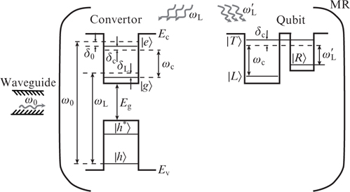
Figure 1. Schematic of a quantum unit consisting of a QD convertor and a DQD qubit.
Download figure:
Standard imageThe convertor in located in the loop of the MR mode, for which the frequency ωc of the operating mode is close to the frequency ωeg = εe – εg of the electronic transition |g〉 ↔ |e〉 (hereafter we assume ℏ = 1). The frequency ωe = εe + εh of the exciton transition between the states |vac〉 and |eexc〉 is close to the frequency ω0 of the telecommunication photon, while the radiation frequency ωL of the auxiliary laser corresponds to the frequency ωg = εg + εh of the exciton transition between the states |vac〉 and |gexc〉.
The principle of the convertor operation consists in transforming the initial telecommunication photon of the waveguide into an e-exciton, which, in turn, transforms into a g-exciton with the emission of a photon into the MR mode using the QD. The latter photon takes part in the change of the electronic state (writing information in the memory qubit) of the DQD that also interacts with the MR mode. As for the g-exciton state of the QD convertor, it can be transformed into the vacuum state using the laser. In this case, the convertor returns to the initial state, and the excess energy is removed by the laser field. This step is not necessary, because the g-exciton is not used anymore and so it is sufficient to let the QD relax to the vacuum state. In this case, the QD spontaneously emits a photon with the appropriate frequency. We emphasise that earlier both the exciton qubit and the charge qubit have been considered separately. In our work a quantum memory node, where these two qubits different in structure, transition frequency and relaxation properties are used in one device, is proposed for the first time.
In the present paper, using the numerical solution of the Lindblad equation for the density matrix we find the probability of the photon frequency conversion with the dissipative processes taken into account in resonance and nonresonance regimes. The conditions and the time of complete conversion are found. It is shown that the most practical method for converting the telecommunication photon into the MR photon is to separate this procedure into two stages. The process of writing the photon state in the memory qubit based on a single-electron DQD is studied. The time required for the absorption of the MR photon in the process of electronic transition in the DQD with subsequent removal of the arriving energy by the laser field is calculated. The properties of the whispering gallery eigenmode of the disk GaAs MR are investigated and the possibility of tuning its spectrum by depositing an additional layer on its surface is shown. The effect of the layer parameters on the radiation Q-factor and the distribution of the electric field in the MR is considered.
2. Frequency convertor based on a single quantum dot
Let us present the Hamiltonian of the 'QD + waveguide + MR + laser' system shown in the left-hand part of Fig. 1 as a sum H0 of the Hamiltonians of individual non-interacting subsystems and the Hamiltonians Hw – QD, Hc – QD and HL – QD, describing the interaction between them:


where a and aw are the photon annihilation operators in the modes of the MR and the waveguide, respectively; and Ωw, Ωc and ΩL are the coupling energies (Rabi frequencies) characterising the intensity of interaction between the subsystem. For further analysis it is convenient to introduce the detunings (frequency differences) δc = ωeg – ωc, δ0 = ωe – ω0 and δL = ωg – ωL. Depending on the relation between the absolute values of the detunings and the Rabi frequencies, the systems will demonstrate different evolution. Here we restrict ourselves to the consideration of the coherent dynamics, using the formalism of the state vector |Ψ 〉 that obeys the Schrödinger equation

where H = H0 + Hw – QD + Hc – QD + HL – QD. The basis vectors are chosen such that their energy does not exceed the doubled energy of the telecommunication photon, which follows from the setting of the problem. Besides that, we assume that two excitations (e.g., e- and g-excitons or an exciton and an electron) cannot be present in the QD simultaneously, since it would violate the resonance conditions (see below) because of the large energy of their electrostatic interaction. Then the basis is expressed as:
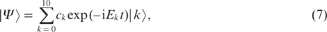
where the first symbol in the notation of an arbitrary vector is the number of telecommunication photons in the waveguide (nw = 0, 1), the second symbol denotes the QD exciton state (vac, eexc, gexc) and the third one is the number of photons in the MR (nc = 0, 1) with the above assumptions taken into account.
Let us present the state vector of the system in the form of expansion over the basis vectors with time-dependent coefficients (probability amplitudes):
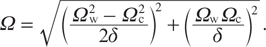
where Ek is the energy of the kth basis state. The substitution of Eqn (7) into the Schrödinger equation (5) yields an equivalent system of differential equations that determine the coefficients ck, which splits into three independent subsystems. The first subsystem,
describes the creation/collapse of a g-exciton under the action of the laser field in the absence of photons in the waveguide and MR. The second subsystem,
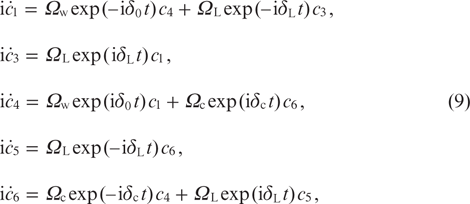
describes the complex exciton – photon dynamics that, in particular, allows the implementation of the photon – photon conversion process. Finally, the third subsystem,
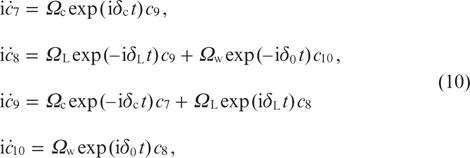
describes the energy exchange between the QD, the laser radiation and the waveguide (MR) under the condition that the waveguide (MR) already contains one photon. Since the initial states are chosen to be |0〉 or |1〉, for which the probability amplitudes do not enter system (10), we do not consider these processes below.
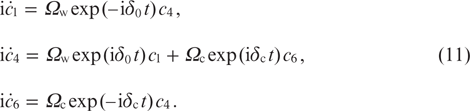
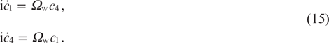
The simplest method of conversion is based on the quantum-field process, in which the telecommunication photon decays into an MR photon and a g-exciton via the intermediate e-exciton state: |1〉 ↔ |4〉 ↔ |6〉. State |4〉 can possess considerable or negligibly small population depending on the resonance or Raman character of the energy exchange between the subsystems. Since no laser radiation is used, the evolution of the system is described by equations (9), where ΩL = 0 is taken into account:
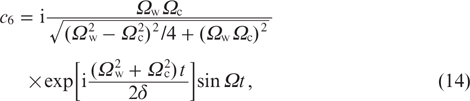
The condition of exact resonance has the form δ0 = δc = 0, and the probability amplitude of the final state |6〉 is

where  . Obviously, for the full conversion (c6 = 1) the equality of Rabi frequencies Ωw = Ωc is required. Then the desired result is achieved during the time
  . Note that in the general case of nonzero detuning the full conversion also requires the fulfilment of the double resonance condition δ0 = δc = δ. Another limiting situation takes place when the detuning δ appears to be much greater than the Rabi frequencies: |δ| ≫ Ωw(c). In this case, the intermediate state |4〉 is practically not populated, and it is possible to use the adiabatic exclusion procedure, as a results of which the three-level system (11) is reduced to the effective two-level system
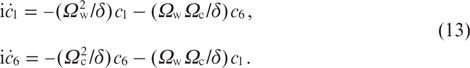
Its solution has the form
where
The difference of Rabi frequencies reflects the disbalance of the energy exchange rates in the 'QD – waveguide' and 'QD – MR' subsystems and plays the role of an effective detuning. We see that, as in the resonance case, the condition Ωw = Ωc is necessary for the realisation of the full conversion to the phase factor exp(iπ/2). The time required for the conversion in the nonresonance regime is  , which is essentially greater than in the resonance regime. The corrections to the solution related to the parasitic population of the intermediate state appear to be of the order of Ω2/|δ| ≪ 1, as well as the additional phase (Stark) shift that enters the exponential factor in Eqn (14). Note that after the fabrication of the structure, it is rather difficult to measure the Rabi frequencies for the waveguide and MR. They are determined by the position, size and orientation of the QD relative to the antinodes of the quantum fields and, therefore, it is not simple to satisfy the balance condition. The solution that allows this limitation to be removed consists in the separation of the three-level scheme into two sequentially executed two-level resonance schemes. This is achieved by the varying the appropriate detunings (assuming the total time τs spent on the switching to be small compared to the period of Rabi oscillations). At the first stage the frequencies of the waveguide and QD are in resonance (δ0 = 0, |δc| ≫ Ωc), and at the second stage the frequencies of the MR and QD are in resonance (δc = 0, |δ0| ≫ Ωc). At first the state |1〉 transforms into the state |4〉 in accordance with the law c4 = − isinΩwt during the time T1 = π/(2Ωw), and then the state |4〉 transforms into the state |6〉 according to the law c6 = − isinΩct during the time T2 = π/(2Ωc). We see that in this case the parameters Ωw and Ωc are independent, and the conversion time Tconv = T1 + T2 + τs is comparable with the conversion time for the single-stage nonresonance scheme.
In order to return the QD into the initial (vacuum) state during the time, smaller than the relaxation time of the g-exciton, it is necessary to expose it to the inducing laser radiation. However, in the absence of a telecommunication photon this radiation will stimulate also the parasitic transition |0〉 → |2〉 from the vacuum state to the g-exciton state, described by system (8). To suppress this process, the detuning of the laser radiation frequency should be significantly greater than the Rabi frequency |δL| ≫ ΩL and satisfy the condition of two-photon resonance δL = −δc = δ.
The change of transition frequencies in the QD occurs due to the action of the electrostatic field of the gate VG [13]. It allows the regulation of the effective energy exchange rate within the 'QD – MR' and 'QD – laser radiation' subsystems. The photon – photon conversion is implemented in two stages. At the first stage, the telecommunication photon is resonancely absorbed by the QD at VG, tuned off the MR resonance, which follows from the solution of system (9), where the conditions ΩL = 0, |δc| ≫ Ωc and δ0 = 0 are taken into account:
The solution c4 = −i sinΩwt shows that the full conversion of the photon into the e-exciton with an accuracy to the phase factor of exp(−iπ/2) is achieved during the time T1 = π/2Ωw. The second stage begins from the change of the electric field that tunes the QD off the resonance with the waveguide and implements the frequency configuration, for which the condition of two-photon Raman resonance between the MR and the laser radiation is satisfied: δL = −δc = δ, |δ0| ≫ Ωw and |δ| ≫ Ωc (L). This choice of the parameters makes the parasitic transition |0〉 ↔ |2〉 inefficient. The system of equations describing the behaviour of the QD, follows from (9) with these conditions taken into account:
The intermediate state |6〉 (the g-exciton in the QD and one photon in the MR) is populated virtually, which again allows its adiabatic elimination and the reduction of the three-level system (16) to the two-level one:
The system of equations (17) will be equivalent to system (13) after the replacement c1 → c5, c6 → c4 and Ωw → ΩL. Therefore, for populating the final state |5〉 with the probability equal to unity, it is again necessary to choose the Rabi frequencies balanced: Ωc = ΩL. The duration of the second stage is calculated using the analogous formula  . Thus, with an accuracy to the phase shift exp(iπ) the total time of the photon – photon conversion is Tconv = T1 + T2.
3. Memory qubit based on a double quantum dot
After completing the conversion, it is possible to proceed to the writing of the MR photon state in the memory qubit based on a single-electron asymmetric DQD. The qubit is stored in the form of superposition of the ground states |L〉 and |R〉 of the DQD, localised in the left-hand and right-hand QD, respectively (Fig. 1, right-hand part). The excited hybrid state |T〉 of the DQD is used as a transport level. The optical transfer of the electron between the state |L〉 and |R〉 is described by the Raman three-level scheme, in which the transition |L〉 ↔ |T〉 is excited by the MR field, and the transition |R〉 ↔ |T〉 by the laser radiation. Therefore, the nontrivial evolution of the electron in the DQD will take place only if the state of the photonic qubit was |1c〉 (one telecommunication photon in the waveguide). The total Hamiltonian of the DQD interacting with the MR field and the laser field has the form
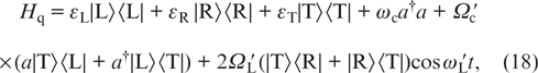
where εL, εR and εT are the energies of single-electron states of the DQD, and  and
and  are the energies of the DQD coupling with the MR and the laser field (Rabi frequencies). The laser radiation frequency
  is chosen different from the frequency ωc of the MR in order to support the selectivity of the transitions in the three-level system. Let us define the detunings for the considered system, namely,
  and
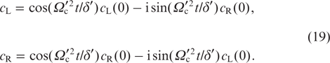
and  , and take the relation εL ≠ εR into account. Let the initial state of the DQD be |Ψq(0)〉 = cL(0)|L〉 + cR(0)|R〉, and the MR be in the state |1c〉. Let us choose the coupling energies and the detunings of the frequencies of laser radiation and the MR to satisfy the conditions of two-photon resonance
  , of adiabatic transfer
  and of the balance of Rabi frequencies
  . Then, with an accuracy to the phase factor
  , the evolution of the DQD state vector will be described by the equations
We again draw attention to the fact that in the absence of a photon in the MR the initial state of the qubit does not change. This means that in general the described algorithm allows the conditional operations to be realised with the charge qubit and the entangled electron – photon states to be generated. Of interest for us is the process of writing the photon, qubit arriving from the quantum network via the waveguide, into the charge memory qubit in the initial state completely localised in one of the QDs (e.g., in |L〉):

Setting cL(0) = 1 and cR(0) = 0 in Eqn (19) and taking the above results into account, we see that the quantum state of the telecommunication photon (possibly, with an accuracy to phase factors to be corrected) is transferred into the state of the DQ qubit during the time Twrite = Tconv = Tabsorb, the time Tconv depending on the conversion method. The time required for the MR photon absorption in the process of the electronic transition in the DQD followed by the removal of the acquired energy by the laser field is  .
.
4. Photon frequency conversion with dissipation taken into account
For more detailed quantitative analysis of the proposed scheme, it is required to find the numerical solution of the Lindblad equation for the density matrix of the system. This equation correctly describes all dissipation effects omitted in the process of deriving the analytical solution of the Schrödinger equation. Moreover, we will explicitly introduce the time dependence of frequency detunings and laser field amplitude, reflecting the finite duration of their switching on/off. It is convenient to use the reference frame in which the energies of the basis states are replaced with the frequency detunings of the transitions between them from the frequencies of the waveguide, the MR and the laser field using the unitary transformation
Transformation (21) modifies the Hamiltonian H in Eqn (5) into the Hamiltonian

where
In Eqn (22) the rotating wave approximation was used that allowed the high-frequency oscillating exponents to be neglected in the last line. Let us introduce the nonunitary operators Am, corresponding to different physical processes of the coherence loss due to the contact of our device with the environment. These processes are: 1) the waveguide photon leakage into the modes of a continuum with the rate κw, Aw = |0〉 〈1| + |2〉 〈3|; 2) the loss of the photon from the MR with the rate κc, Ac = |0〉 〈5| + |2〉 〈6|; 3) the e-exciton collapse in the QD during the time τexc e, Aexc e = |0〉 〈4|; 4) the g-exciton collapse in the QD during the time τexc g, Aexc g = |0〉 〈2| + |1〉 〈3| + |5〉 〈6|; 5) the QD electron intersubband relaxation during the time τeg, Aeg = |2〉 〈4|; 6) the e-exciton dephasing during the time τdeph e, Adeph e = |4〉 〈4|; and 7) the g-exciton dephasing during the time τdeph g, Adeph g = |2〉 〈2| + |3〉 〈3| + |6〉 〈6|.
Processes 3) – 7) are caused by the interaction of the exciton with the phonon reservoir and the stochastic fluctuations of the fields of the controlling gates. In our work, we do not consider more complex two- and three-particle processes (e.g., simultaneous photon – phonon relaxation of the QD and MR). The Lindblad equation for the density matrix ρ of the system has the form

where  is the partial Lindblad operator characterising the decay of a certain quantity, corresponding to the operator Am (
 is the decay rate).
The time dependences of the detunings are related to the slowly varying electric potential at the metallic gate placed near the QD. We specify them phenomenologically, keeping in mind the following qualitative considerations: 1) when the positive voltage VG > 0 is applied to the gate, the depth of the QD increases, and the difference between its electronic energy levels (the transition frequency) decreases, Δωeg < 0; and 2) the energy of the exciton as a neutral particle changes much weaker than the energy of the excited electron, Δωeg ≪ Δωe(g). The smooth variation of the potential provides the smoothness of detunings as functions of time in the intervals, corresponding to the processes of switching on/off. They are modelled with tangential dependences
where k = 0, c, L; T1 = t2 − t1 is the duration of pulse A; T3 = t4 − t3 is the duration of pulse B; T2 = t3 − t2 is the interval between pulses A and B; and τ is the time of switching the pulses on/off. The pulse amplitudes δAk and δBk are chosen to satisfy the conditions imposed by the conversion algorithm. Moreover, we take into account the finite duration of the laser pulse (if present) at the second stage of the conversion, using the analogous function for the laser amplitude (Rabi frequency):

The parameters in Eqns (22) – (25) are chosen using the presently available experimental data and the estimates made for the optimal versions of the device.
Let us present the results of numerical calculations that illustrate the conversion algorithm for several above-described methods. All energy quantities are expressed in units of the frequency ω0 of the telecommunication photon. For approximate quantitative estimates it is possible to set ω0 ≈ 1 eV. We assume that the MR is transparent for the waveguide and laser photons. The field strength Ec in the antinodes of the single-photon field of the MR mode can attain a few hundreds or even thousands V cm−1. The dipole moment dQD of the QD can be estimated as eaQD, where aQD is the characteristic size (radius) of the QD. Assuming Ec = 102 eV and aQD = 10 nm, for the QD located in the antinode of the MR mode we obtain the Rabi frequency Ωc ∼ EcdQD ∼ 10−4 eV. In a real structure this value will be significantly smaller, and in the calculations we use the estimate Ωc ∼ 10−5 eV or Ωc ∼ 10−5 in units of ω0. The optimisation of the interaction of the waveguide and the QD exciton transition also requires spatial coincidence of the waveguide field antinode and the QD coordinate. In our work we assume this condition to be satisfied and set Ωc ≈ Ωw. The range of variation of the detunings (QD energy level shifts) in the gate fields 0 < |VG| < 10 V, as follows from the experiments, lies within a few electronvolts. Therefore, in Eqn (24) we set |δk|, |δAk|, |δBk| ∼ 10−3. The most difficult choice is that of the dissipation and dephasing rates, since these processes are responsible for the reduction of the conversion probability Pconv (provided that all other conditions are met). To date, the MR with Q-factors Q ∼ 106 are already available, but to achieve Pconv > 0.9 this is not sufficient and perfect MRs are required. In the calculations, we assume Q ∼ 107, hoping for the progress in the fabrication of optical microstructures.
Now consider the two-stage conversion algorithm (15) – (17), where the first stage is presented by the two-level resonance scheme and the second stage by the three-level (or effective two-level) scheme. The parameters of the pulses (Fig. 2) are chosen in correspondence with the calculations. As one can see, due to the long time of the second stage, in spite of the suppression of the g-exciton relaxation and the elimination of the parasitic excitation of the vacuum state by the laser field, the presence of the photonic relaxation channels considerably reduces the conversion probability as compared to the solution obtained in the coherent approximation. Therefore, the successful application of the present scheme requires increasing the MR Q-factor and the appropriate Rabi frequencies.
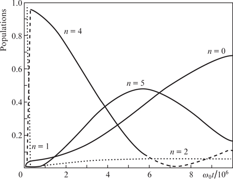
Figure 2. Time dependences of the population of the basis states in a two-stage combined scheme with laser radiation for Ωw = 0.8 × 10⁻⁵, Ωc = 10−5, κw(c) = 10−7, γe(g, eg) = 10−8, γdeph e(g) = 10−8, δc = – δL = 0.4 × 10⁻³.
Download figure:
Standard imageConsider the version of two-stage resonance conversion without using the laser radiation, which, in our opinion, is most simple and efficient. The detuning parameters for the A and B pulses are chosen as shown in Fig. 3a. This choice provides a sequential switching on/off of the resonance between the waveguide and the MR, on the one hand, and the QD, on the other hand. The numerical solution (Fig. 3b) clearly shows that at similar parameters this scheme is the most reliable among three others. We recall that in such a scheme the auxiliary exciton is removed from the system via the spontaneous relaxation. The probability of conversion is Pconv = 0.95 and can be increased, as already mentioned above, by improving the quality of the structure fabrication.
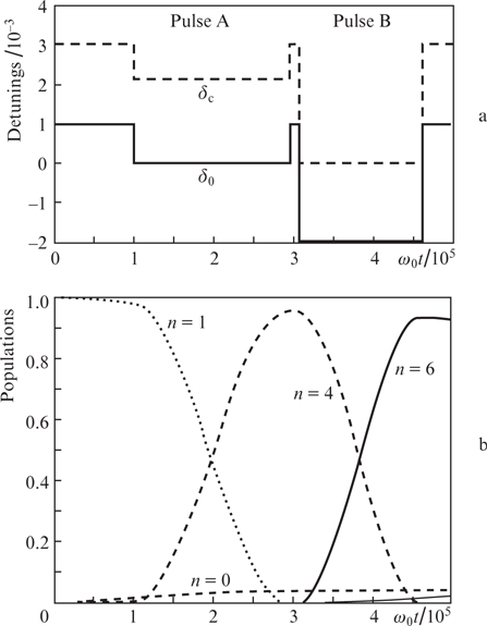
Figure 3. Time dependences of (a) frequency detunings and (b) basis state populations in the two-stage resonance scheme without laser radiation for δA 0 = 10−3, δB 0 = 3 × 10⁻³, δA c = 0.9 × 10⁻³, δB c = 3 × 10⁻³, τ = 0.5 × 10³, t1 = 105, Ωw = 0.8 × 10⁻⁵(a) и Ωc = 10−5, κw(c) = 10−7, γe(g, eg) = 10−8, γdeph e(g) = 10−8 (b).
Download figure:
Standard image5. Modelling spectral characteristics of microdisk resonator with additional layer
Let us discuss one of the possible ways to improve the MR performance properties. It is known that the optical MRs, supporting the whispering gallery modes (toroids, spheres, rings and disks), possess a small volume of the optical mode and a high Q-factor. This allows their use in the applications of quantum electrodynamics [14–16], nonlinear optics [17], optomechanics [18], as well as in the development of lasers [19]. As shown theoretically in Ref. [7], it is possible to implement single- and double-qubit quantum operations with high accuracy, by using the DQDs embedded in a GaAs disk MR. The fabrication of a MR with the frequency of one of its eigenmodes, coincident with that of the electronic transition in the QD, is rather challenging. Therefore, for the correction of the MR spectrum different methods are used, e.g., heating, surface oxidation, as well as deposition of an additional layer (AL) of a substance with a different refractive index (see, e.g., review [8]).
The spectral characteristics of the microdisk with an AL were calculated within the frameworks of the following model. Let us consider a disk having a radius R and a thickness h0 made of material with a refractive index n0. The disk surface is coated with the AL having a thickness hlayer and a refractive index nlayer. For the TM modes the boundary conditions for the electromagnetic field at the side surface of the disk (ρ = R) yield the equation [7,20–22]

where k0 is the wave vector of the photon in vacuum; Jm is the Bessel function of the first kind; Hm is the Hankel function of the first kind; and m is the azimuthal number. The presence of the effective refractive index n in expression (26) is related to partial reflection of the electromagnetic wave from the interface separating the regions z = 0, z = h0, z = h0 + hlayer. Using the continuity of the radial and azimuthal projections of the electric field and taking the jump of its axial projection at the above boundaries into account, we arrive at the equation
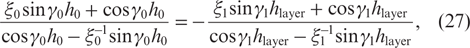
where we introduced the dimensionless parameters  , and the quantities γ0(1) and γ are expressed in terms of ñ as
The self-consistent solution of Eqns (26) and (27) allows one to find the wave vector kp of the TMm p eigenmodes of the disk, where p enumerates the solutions of Eqn (26). In the absence of the AL (hlayer = 0 or nlayer = 1), Eqn (27) takes the form

In this case, due to the symmetry with respect to the z axis, Eqn (29) splits into two equations

that yield even and odd solutions (see, e.g., [23]).
As already mentioned above, the functioning of the quantum memory unit requires a Q-factor of one of the MR eigenmodes to be not smaller than 107. The Q-factor value Q is determined by different loss channels, e.g., the escape of photons from the MR (radiation losses), the scattering and absorption of photons inside the MR and on its surface, etc. Obviously, the Q-factor cannot exceed the value, related to each of the channels, in particular, the radiation Q-factor [22]

which, therefore, should be greater than 107. This condition is satisfied by the whispering gallery modes of the disks (p = 1) with large values of m, in which the antinodes of the electric field are localised at the side surface [24]. Hence, the efficient interaction between the QD and MR will be achieved only if the QD is localised near the disk edge. Besides that, the mode frequency ωc = ckp (c is the speed of light in free space) should approximately equal the difference of energies of the ground and excited states of the electron in the QD conduction band (see. Fig. 1) that amounts to nearly 0.1 eV (ℏ = 1). The spectral characteristics of the even TM modes of the GaAs disk (n0 = 3.4) without the AL have been studied in detail in Ref. [7]. In this paper the eigenfrequency ωc was calculated and the maximal value Emax of the single-photon electric field strength inside the MR was determined as a function of the disk size.
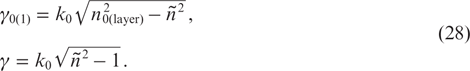
It is difficult to fabricate the MR with the required value of ωc because of technological errors that affect the optical spectrum. One of the most frequently used ways of tuning the MR eigenfrequency is to deposit on its surface an additional layer of a material having a different refractive index [25–27]. However, the AL can negatively affect the values of Qrad and Emax. We calculated the dependence of ωc, Qrad and Emax on the AL thickness hlayer at different values of its refractive index nlayer for the TM15 1 mode of the GaAs disk having the radius R = 10 μm and the thickness h0 = 2.5 μm (Fig. 4). In the absence of the AL (hlayer = 0) the mode eigenfrequency ωc is equal to 0.13 eV; the maximal value of the field Emax and the Rabi frequency Ωc amount to 17.6 V cm−1 and ∼10−5 eV, respectively. With the growth of hlayer, the values of ωc and Emax decrease and Qrad monotonically increases. The greater the refractive index of the AL, the stronger the growth of the Q-factor and the fall of ωc and Emax. Moreover, while for nlayer = 4.2 and hlayer varying from 0 to 0.6 μm the frequency ωc decreases by 10%, staying near the value of 0.1 eV, the radiation Q-factor Qrad increases by an order of magnitude from 109 to 1010. The maximal value of the field and, therefore, the Rabi frequency Ωc in this case decrease by 20%. Figure 5 shows the transverse distribution of the z-component of the electric field strength Ez (ρ, φ = 0, z) for hlayer = 0.6 μm at different values of the refractive index nlayer. It is seen that for nlayer < n0 the electric field is localised in the disk, and for nlayer > n0 the field penetrates into the AL, which is accompanied by a much greater fall of its maximal value Emax (see Fig. 4c). Therefore, despite the fact that the deposition of the AL with the refractive index exceeding that of the disk allows more efficient tuning of the MR optical spectrum, it can lead to a considerable decrease in the interaction between the MR and the QD and, thus, reduce the probability of telecommunication photon conversion.

Figure 4. Dependences of (a) the eigenmode frequency ωc, (b) the radiation Q-factor Qrad and (c) the maximal value Emax of the electric field on the AL thickness hlayer for different values of its refractive index nlayer and R = 10 μm, h0 = 2.5 μm. The inset presents the distribution of the electric field z-component Ez in the plane z = (h0 + hlayer)/2 at hlayer = 0.6 μm. The dashed line shows the cross section in which the transverse distributions of the field in Fig. 5 were calculated.
Download figure:
Standard image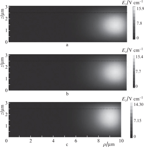
Figure 5. Transverse distribution of the z-component of the electric field Ez for hlayer = 0.6 μm and nlayer = (a) 3.0, (b) 3.4 and (c) 4.2. The dashed line shows the face surface of the microdisk (z = h0) in the absence of the AL.
Download figure:
Standard image6. Conclusions
Thus, the concept of a device consisting of a memory qubit and a frequency convertor is proposed and analysed. The memory qubit is represented by a semiconductor four-level DQD placed in a MR. The DQD contains one electron in the quantised part of the conduction band, and the MR can be populated by a certain number of photons. To control the DQD and MR states the laser and electrostatic fields are used. The difference between the frequency of the telecommunication photon (transport qubit) supplied to the system via a waveguide and that of the electronic transition in the DQD is compensated for using an auxiliary element, i.e., a frequency convertor based on a single QD.
Solving numerically the Lindblad equation for the density matrix, we have determined the probability of the frequency conversion of the photon with the dissipation processes taken into account in the resonance and nonresonance regimes. The conditions and time of the full conversion are found. By comparing the two-level and three-level resonance schemes, we have found that the number of conditions necessary to implement the transfer in the three-level scheme is greater than in the two-level scheme. As to the purely virtual single-stage conversion scheme, each additional nonresonance transition reduces the effective Rabi frequency by an order of magnitude. In this case, even a minor deviation from the conditions of Raman resonance will lead to the suppression of two-level oscillations. Besides that, the lower boundary of the conversion rate is determined by the dissipation processes (spontaneous relaxation of the QD, the escape of photons from the waveguide and MR and other more complex effects). Thus, using the obtained results, one can conclude that the most practical way of converting the telecommunication photon into the MR photon is to separate this procedure into a few simple stages, while the slow nonresonance processes should be used only when necessary (e.g., with the purpose of blocking the parasitic transitions).
We have developed a technique for numerical modelling of the optical spectrum of a microdisk GaAs MR with the Al depositied on its surface. Based on the present technique we have studied the effect of the AL on the properties of the MR eigenmode and showed the possibility of tuning its frequency to the frequency of the electronic transition in the QD by applying the AL on the disk surface. Besides that, we have examined the AL influence on the radiation Q-factor and the electric field distribution in the MR. It is found that the deposition of the AL with the refractive index exceeding that of the disk material allows more efficient tuning of the MR optical spectrum, but can lead to a considerable decrease in the interaction between the MR and the QD and reduce the probability of the telecommunication photon conversion.