Abstract
This study presents a simple, miniaturized, and low-profile multiple-input multiple-output (MIMO) antenna operating at 29 GHz with reduced mutual coupling between the antenna elements for futuristic 5G communication. The proposed design employs two radiating elements with slits in the radiators to produce high isolation among the antenna radiators. The MIMO antenna maintains a compact structure of 11.4 × 5.3 mm2, which is the smallest size compared to previous 5G antennas. Roger’s 4350B laminate was employed as a substrate material. At 29 GHz, low mutual coupling of − 36 dB, low envelope correlation coefficient (ECC < 0.001), and high diversity gain (DG > 9.8 dB) are achieved. The proposed design is examined in terms of the S-parameters, diversity gain, radiation pattern, and envelope correlation. Compared to the straight antenna element, an improvement of − 20 dB is observed in the isolation for both the simulated and measured results.
Introduction
With the increasing demand for high data rates, MIMO antennas have gained significant attention and are considered a key technology in millimeter-wave communication. MIMO technology is highly recommended owing to its promising features of enhanced data transmission speed, coverage area, and resistance to multiple paths fading1,2. However, mutual coupling due to surface wave propagation and inadequate isolation among the elements of a massive MIMO system causes poor impedance and radiation performance and degrades channel capacity3. Increasing the physical distance between the radiators is a simple manner to achieve high isolation, but it results in a large antenna size. Researchers have attempted to develop methods to maximize the packing density while enhancing the isolation between the radiators. Thus, optimizing mutual coupling would be significant in wireless communication systems.
A MIMO antenna incorporates minimum two radiating elements, placed at a specific distance to achieve minimum mutual coupling between them, but very limited space is available in front-end modern communication systems. Different approaches have been recommended by the researcher to reduced mutual coupling between the radiators. In4, a stub on the lower ground plane was used in perpendicularly placed radiators to achieve minimum mutual coupling. In5, more than 20 dB isolation is observed among the MIMO patch antennas by using near field resonator above each antenna elements. A tree-shaped MIMO antenna structure was proposed in6 with isolation > 16 dB over the entire ultrawide band. In7, isolation was increase by adjusting the structure of the ground plane under each resonator in order to make mutual coupling out-of-phase between the ground plane and free space which cause in isolation enhancement by more than 10 dB between the diagonal and adjacent elements. However, this approach increased the thickness of the antenna, reducing its wider applications in low-profile arrays. In8, six metal strips were incorporated between the radiators to efficiently reduce the mutual coupling without affecting the gain and radiation pattern. Another approach is to use slits in the ground plane, but it cause in backward radiation9. Similarly, mender line slots, L- and T-shaped ground branches were added to the ground plane resulting in high isolation at the cost of fabrication complexity10,11,12. In13, a novel parasitic decoupling technique is proposed having efficiency more than 64% for closely coupled antenna. Similarly a Wilkinson power divider is used as to enhance isolation between the radiators as shown in14.
Researchers have suggested remarkable techniques to reduced mutual coupling between the radiators, such as employing a defective ground plane15, electromagnetic bandgap structures16, and a perpendicular feeding network17. In18, parasitic F-shaped stubs were used between the radiating patches to achieve good isolation. An electric-LC resonator was used at two-element MIMO antenna for mutual coupling reduction19. In20, a Y-shaped stub ensued by rectangular slots in the ground plane was employed for better isolation between wrench MIMO antennas. In21, neutralization line is presented for the first time to achieve isolation enhancement. Each neutralization line consists of metal strip and in the middle of antenna elements a reactive component attached.
This study proposes a low-cost, low-profile, miniaturized two-element-based MIMO antenna system with significantly reduced mutual coupling of S21 < − 36 dB. The antenna elements are rotated at 45° in the clockwise direction, and two slots are introduced in the radiating part to achieve better isolation in these closely packed elements. These slots extend the physical separation between the resonators, resulting in high isolation22. The antenna has a simple structure which is excited using a 50-Ω feedline. The proposed design is employed on a Rogers 4350B laminate with a thickness of 0.8 mm. Satisfactory agreement between both the simulated and measured results was obtained, which emphasizes that the proposed design could be a prime candidate for 5G communication because of its low envelope correlation, high diversity gain, and low mutual coupling between the radiators.
Antenna configuration
The proposed antenna elements are evolved from simple rectangular shape patch antenna. The detailed dimensions of proposed MIMO antenna are determined using the well-known transmission line theory23. The effective resonant length (Lre) and width (W) for specific resonant frequency (fr) are calculated using mentioned theory23:
Similarly, h is the thickness of the substrate, c is the speed of light, \({f}_{r}\) is the resonance frequency, and \(\Delta L\) represents the differtial change in length due to fringing. Furthermore, \({\varepsilon }_{o},{\varepsilon }_{r ,}\) and \({\mu }_{o}\) are the free space permittivity, relative permittivity, and permeability of free space, respectively. Using the above mentioned equations, dimensions of the presented antenna were obtained for 29 GHz.
The design evolution of the two-element MIMO design is presented in Fig. 1. The proposed MIMO antenna has overall dimensions of 11.4 × 5.3 × 0.8 mm3, which occupies less volume compared to other antennas. Two radiating patches with slits, rotated at 45°, are printed on Roger 4350B substrate with 0.8 mm thickness and relative permittivity of 3.66. The length and width of the radiators were 3.62 mm and 2.7 mm, respectively. The substrate is backed by a common ground plane. Initially, straight antenna elements were designed, each operating at 36 GHz with mutual coupling S21 < − 16 dB. Low mutual coupling between the patches was observed by introducing slots and rotating them by 45° in the clockwise direction. Slots increased the current path, leading to mutual coupling reduction at the desired frequency of 29 GHz. The slots and stub (left part of a radiator) act as a capacitor and inductor, respectively, forming a parallel LC-equivalent circuit. Figure 1a, shows the straight elements with a center-to-center distance of half of the free space wavelength, i.e., 5.3 mm. Figure 1b, presents antenna elements rotated by 45° in the clockwise direction, while proposed design is shown in Fig. 1c; the fabricated prototype is shown in Fig. 1d.
The proposed MIMO design operates at 29 GHz with dimensions of L = 11.4, W = 5.3, Le = 3.6, We = 1.8, Ls = W1 = 0.7 mm, Wm = 1.3, Lm = 1.2, L1 = 1.2, and g = 0.18 (all dimensions in mm). The antenna was modelled and optimized using the commercially available CST MW Studio Suite software.
Results and discussion
The mutual coupling performance of the presented two elements MIMO antenna was analyzed by using the surface current distribution. Initially slots were introduced in the radiators and rotated by 45° in the clockwise direction. The current distribution on the surface of proposed design is shown in Fig. 2. When port 1 was excited, port 2 was terminated with a 50-Ω load. For the straight elements array, more coupling was observed between the two radiators, as shown in Fig. 2a. However, by introducing slots in the radiating elements and rotating each element by 45°, as shown in Fig. 2b, considerable reduction in surface current is observed, which resulted in losses mutual coupling with the neighboring patch.
Figure 3a shows the simulated electric field distribution at 29 GHz. It is shown that antenna 1 is excited while antenna 2 is connected with 50-Ω load. It is evident from the electric field distribution that entire length of antenna patch is responsible for radiation. In the E-plane, the mutual coupling is in the TM mode. For further clarification, simulated magnetic field distribution at 29 GHz is presented in Fig. 3b. It can be observed that the high current densities could be found around the antenna slit which lead to low mutual coupling between the radiating elements. For magnetic fields, TE mode is observed. When the square patch antenna is excited from the diagonal, it has TM01 and TM10 modes with equal amplitude and phase.
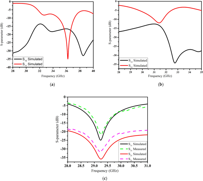
The scattering parameters of the straight elements MIMO antenna are shown in Fig. 4a. This array resonates at 36 GHz with a reflection coefficient (S11) of − 35 dB. The two elements of the antenna are rotated by 45° in the clockwise direction due to which resonance is shifted to 31 GHz with an isolation of − 15.5 dB as shown in Fig. 4b. The slots in the radiator or ground plane increase the effective inductance of the antenna while capacitance has negatively correlated with sloth width3. Therefore, the resonance frequency is reduced to 29 GHz by etching slots in the radiators. As seen in Fig. 4c, compared to the straight elements design, an improvement of − 20 dB was achieved in the mutual coupling for our proposed design. S21 was changed to − 36 dB at the resonance frequency of 29 GHz.
The scattering parameters of the presented MIMO antenna were measured in an anechoic chamber. Satisfactory results were observed for both simulated and measured results, as presented in Fig. 4c. The measured impedance bandwidth was higher than 1 GHz, which is sufficient for 5G communication devices. Similarly, the measured S21 was less than -32 dB at the resonance frequency.
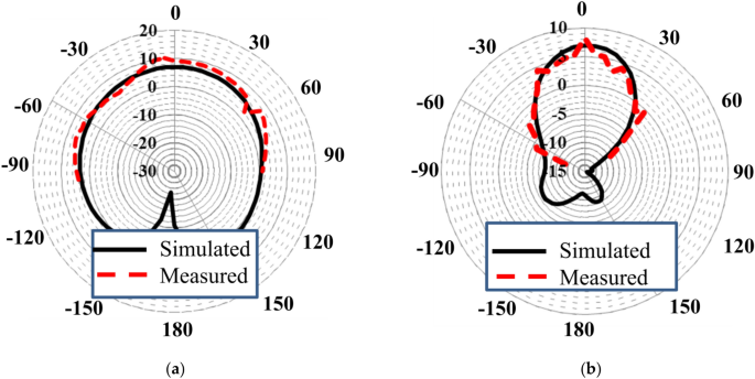
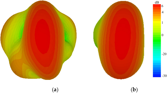
A close agreement was observed between the measured and simulated radiation patterns, as presented in Fig. 5a,b. Radiation patterns were measured with one port excited with 50-Ω feed while terminating the second one by a matching load. According to measurements, maximum gains of 6 and 5 dBi were observed in the E (xz)- and H (yz)-planes. Radiation patterns of the proposed antenna have very small back-lobe radiation, which increases its effectiveness for futuristic applications. The three-dimensional (3D) radiation patterns of the straight-element MIMO and proposed MIMO antenna for 29 GHz are presented in Fig. 6a,b, respectively. High side and back lobs were observed for the straight element MIMO antenna. However, by introducing slots in the radiating patch, main beam is directed towards a specific boresight direction with minimum sides and back lobes, thus making the proposed design efficient for 5G communication.
To validate the compatibility, performance, and efficiency of the proposed millimeter-wave MIMO antenna, envelope correlation coefficient (ECC) was investigated. The ECC is the relation between the incoming signals at the port of the antenna, and it is necessary to calculate the channel quality of the uncorrelated channel. A high ECC value leads to have high correlation and minimum isolation, which degrades antenna performance. Furthermore, ECC shows the mutual effect of the overall S-parameters of the designed MIMO antennas. The ECC can be found using different approaches, i.e., using the received signal envelope or by using S-parameter or far field radiation for estimation of complex cross correlation. In this paper, ECC is calculated by using both S-parameter and far field radiation patterns method as shown in Eqs. (3) and (4), respectively24. While for the measurements, the ECC from radiation patterns, involve a time consuming integral calculation. To ease the measurement process, ECC value of the proposed MIMO antenna system were calculated based on S-parameters using Eq. (3)
where, \({\uprho }_{{{\text{ij}}}}\), represent the ECC. \(\overrightarrow {{{\text{F}}_{{\text{i}}} }} \left( {\uptheta ,\upphi } \right)\) and \(\overrightarrow {{{\text{F}}_{{\text{j}}} }} \left( {\uptheta ,\upphi } \right)\) are the radiation patterns of the i-th and j-th elements of the MIMO antenna, where I, j = 1, 2 for the proposed design.
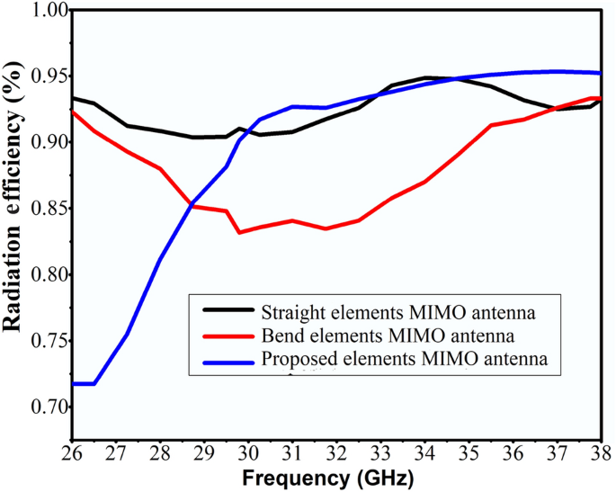
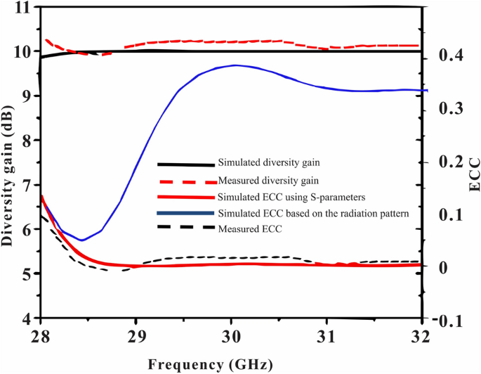
Radiation efficiency of straight elements, bend elements array and proposed elements MIMO antenna are given in Fig. 7. More than 85% radiation efficiency is realized for the proposed MIMO antenna across the operating band. Ideally, the ECC value should be zero. However, in practice, a limit of the ECC < 0.5 is adopted for uncorrelated MIMO25. Figure 8. presents that the proposed MIMO antenna has an ECC value of 0.0001 at the desired band of 29 GHz, which is considerably close to zero.
Diversity gain (DG) is also an important parameter that must be considered when evaluating the performance of MIMO antennas. This parameter is an indicative of the reliability of the MIMO system. Isolation of the radiators is higher for high DG antenna systems26. The following relation can be uses for calculating DG of the MIMO antenna:
Diversity gain (DG) of the presented MIMO antenna is given in Fig. 8 in a range of frequencies. The presented antenna has a DG > 9.8 dB across the operating band.
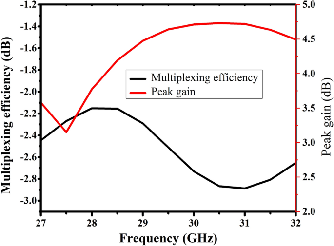
Figure 9 shows multiplexing efficiency and peak gain with varying frequencies. Multiplexing efficiency (ηMux) is calculated by using the following relation:
where ‘\({\uprho }_{\mathrm{c}}\)’ is the complex correlation coefficient between the antenna patches. \(\mathrm{ECC}\approx {\left|{\uprho }_{\mathrm{c}}\right|}^{2}\), and \({\upeta }_{\mathrm{i}}\) is the total efficiency of i-th antenna radiator. Here we used i = 1, 2 as we have two elements MIMO array.
Table 1 presents the comparison of the proposed with some recently published work based on different performance characteristics. In27, a millimeter-wave eight-element MIMO antenna array was proposed using beam tilting and high-isolation dielectric resonator. A minimum isolation of 25 dB and a peak gain of 7 dBi were achieved at the cost of large size and fabrication complexity. Similarly, Yagi–Uda antennas for a millimeter-wave MIMO terminal were presented in28, in which the proposed design achieved a better isolation of 21 dB; a horn-shaped Via was used for the isolation enhancement. A metasurface-based corrugation was used for mutual coupling reduction in29, and a better isolation of 37.1 dB was observed at the desired center frequency of 28 GHz. However, this design has a complex fabrication process. Similarly, in30, a four-port MIMO antenna was designed for millimeter-wave applications, providing better impedance bandwidth but achieving an isolation of only 21 dB with a wide dimension of 48 × 31 mm2. In31, quad-elements MIMO antenna is proposed for UWB applications. By using parasitic elements isolation is improve by 20 dB. In32, four elements MIMO antenna is proposed operating from 23 to 28 GHz, isolation is improve by using defective ground plane.
The proposed MIMO antenna maintained a compact structure of 11.7 × 5.3 mm2, due to the use of slotted and inclined antenna radiators. A better isolation of 36 dB, low ECC values of 0.0001, and high diversity gain of > 9.8 dB were achieved. A close agreement was found between both measured and simulated results, thereby making the proposed design a strong candidate for 5G millimeter-wave communications. The slight difference in measured and simulation results is due to fabrication tolerances.
Conclusions
A compact 2 × 2 MIMO antenna with a shared ground plane was proposed in this study for futuristic 5G communication. Despite the simple geometry, a large reduction in antenna size (11.4 × 5.3 mm2) was achieved by introducing slits in the radiators to increase the current path. High isolation between the resonators was obtained by introducing slots in the patches and rotating them by 45° in the clockwise direction. The simulated results for ECC (ECC < 0.0001), DG (DG > 9.8 dB), and isolation between the radiators (> 36 dB) indicate that the presented MIMO antenna is an efficient candidate for 5G applications. The simulated and experimental results showed good agreement in term of S-parameters, radiation pattern, diversity gain and ECC, despite its miniaturized size in comparison with previous 29 GHz millimeter-wave antennas.
References
Nadeem, I. & Choi, D.-Y. Study on mutual coupling reduction technique for MIMO antennas. IEEE Access. 7, 563–586 (2019).
Chen, X., Zhang, S. & Li, Q. A review of mutual coupling in MIMO systems. IEEE Access. 6, 24706–24719 (2018).
Gao, D., Cao, Z., Quan, X., Sun, M. & Fu, S. C. A low-profile decoupling slot-strip array for 2 × 2 microstrip antenna. IEEE Access 8, 113532–113542 (2020).
Liu, L., Cheung, S. W. & Yuk, T. I. Compact MIMO antenna for portable devices in UWB applications. IEEE Trans. Antennas Propag. 61, 4257–4264 (2013).
Li, M., Bing, G. Z. & Cheung, S. W. Isolation enhancement for MIMO patch antennas using near-field resonators as coupling-mode transducers. IEEE Trans. Antennas Propagat. 67, 755–764 (2018).
Zhang, S., Ying, Z., Xiong, J. & He, S. Ultra-wideband MIMO/diversity antennas with a tree-like structure to enhance wideband isolation. IEEE Antennas Wireless Propag. Lett. 8, 1279–1282 (2009).
Zhang, S., Chen, X. & Pedersen, G. F. Mutual coupling suppression with decoupling ground for massive MIMO antenna arrays. IEEE Trans. Vehicular Technol. 68, 7273–7282 (2019).
Sun, X. B. & Cao, M. Y. Low mutual coupling antenna array for WLAN application. Electron. Lett. 53, 368–370 (2017).
Chen, X. et al. Characterizations of mutual coupling effects on switch-based phased array antennas for 5G millimeter-wave mobile communications. IEEE Access. 7, 31376–31384 (2019).
Hwangbo, S., Yang, H. Y. & Yoon, Y. K. Mutual coupling reduction using micromachined complementary meander-line slots for a patch array antenna. IEEE Antennas Wirel. Propag. Lett. 16, 1667–1670 (2017).
Wang, X., Du, Z. & Gong, K. A compact wideband planar diversity antenna covering UMTS and 2.4 GHz WLAN bands. IEEE Antennas Wirel. Propag. Lett. 7, 588–591 (2008).
Ding, Y., Du, Z., Gong, K. & Feng, Z. A novel dual-band printed diversity antenna for mobile terminals. IEEE Trans. Antennas Propag. 7, 2088–2096 (2007).
Li, M., Lijun, J. & Kwan, L. Y. Novel and efficient parasitic decoupling network for closely coupled antennas. IEEE Trans. Antennas Propagat. 67, 3574–3785 (2019).
Li, M., Lijun, J. & Kwan, L. Y. A novel wideband decoupling network for two antennas based on the Wilkinson power divider. IEEE Trans. Antennas Propagat. 68(7), 5082–5094 (2020).
Zhu, F.-G., Xu, J.-D. & Xu, Q. Reduction of mutual coupling between closely-packed antenna elements using defected ground structure. Electron. Lett. 45, 601–602 (2012).
Suntives, A. & Abhari, R. Miniaturization and isolation improvement of a multiple-patch antenna system using electromagnetic bandgap structures. Microw. Opt. Technol. Lett. 55, 1609–1612 (2013).
Adamiuk, G., Beer, S., Wiesbeck, W. & Zwick, T. Dual-orthogonal polarized antenna for UWB-IR technology. IEEE Antennas Wireless Propag. Lett. 8, 981–984 (2009).
Iqbal, A., Saraereh, O. A., Ahmad, A. W. & Bashir, S. Mutual coupling reduction using F-shaped stubs in UWB-MIMO antenna. IEEE Access. 6, 2755–22759 (2017).
Pandit, S., Mohan, A., Ray, P. A compact planar MIMO monopole antenna with reduced mutual coupling for WLAN applications using ELC resonator. in Proc. IEEE Microw. Conf. (APMC), pp. 1–4 (2016).
Verma, A.K., Nakkeeran, R., Vardhan, R.K. Design of 2_2 single sided wrench shaped UWB MIMO antenna with high isolation. in Proc. IEEE Int. Conf. Circuit, Power Comput. Technol. (ICCPCT), pp. 1–3 (2016).
Li, M., Jiang, L. & Yeung, K. L. A general and systematic method to design neutralization lines for isolation enhancement in MIMO antenna arrays. IEEE Trans. Vehicular Technol. (2020).
Karaboikis, M., Soras, C., Tsachtsiris, G. & Makios, V. Compact dual-printed inverted-F antenna diversity systems for portable wireless devices. IEEE Antennas Wirel. Propag. Lett. 3, 9–14 (2004).
Balanis, C. A. Antenna Theory: Analysis and Design 3rd edn. (Wiley, 2005).
Blanch, S., Romeu, J. & Corbella, I. Exact representation of antenna system diversity performance from input parameter description. Electron. Lett. 39, 705–707 (2003).
Ying, Z., Chiu, C. -Y., Zhao, K., Zhang, S. & He, S. Antenna design for diversity and MIMO application. in Handbook of Antenna Technologies, 1–43 (Springer, 2015). https://doi.org/10.1007/978-981-4560-75-7_53-1.
Sibille, A., Oestges, C. & Zanella, A. MIMO: From Theory to Implementation (Academic Press, 2010).
Sharawi, M. S., Podilchak, S. K., Hussain, M. T. & Antar, Y. M. M. Dielectric resonator based MIMO antenna system enabling millimetre-wave mobile devices. IET Microwaves Antennas Propagat. 11, 287–293 (2017).
Hsu, Y.-W., Huang, T. C., Lin, H. S. & Lin, Y. C. Dual-polarized quasi Yagi-Uda antennas with endfire radiation for millimeter-wave MIMO terminals. IEEE Trans. Antennas Propagat. 65, 6282–6289 (2017).
Gupta, S., Zouhair, B., Abdel, R., Sebak, T. & Ahmed, D. Mutual-coupling reduction using metasurface corrugations for 28 GHz MIMO applications. IEEE Antennas Wireless Propagat. Lett. 16, 2763–2766 (2017).
Wani, Z., Abegaonkar, M. P. & Koul, S. K. A 28-GHz antenna for 5G MIMO applications. Progress Electromagnet. Res. 78, 73–79 (2018).
Amin, F., Rashid, S., Tayyab, S., Muhammad, B. & Shafique, M. F. A compact quad-element UWB-MIMO antenna system with parasitic decoupling mechanism. Appl. Sci. 11, 2371 (2019).
Sharma, S., Kanaujia, B. K. & Khandelwal, M. K. Implementation of four-port MIMO diversity microstrip antenna with suppressed mutual coupling and cross-polarized radiations. Microsyst. Technol. 26, 993–1000 (2020).
Author information
Authors and Affiliations
Contributions
Conceptualization, A.A. and D.Y.C.; methodology, A.A.; software, A.A.; validation, A.A, D.Y.C, and S.U.; formal analysis, A.A.; investigation, A. A and D.Y.C; resources, D.Y.C.; data curation, A.A, S.U and D.Y.C.; writing—original draft preparation, A.A.; writing—review and editing, S.U and D.Y.C.; visualization, D.Y.C.; supervision, D.Y.C; funding acquisition, D.Y.C All authors reviewed the manuscript.
Corresponding author
Ethics declarations
Competing interests
The authors declare no competing interests.
Additional information
Publisher's note
Springer Nature remains neutral with regard to jurisdictional claims in published maps and institutional affiliations.
Rights and permissions
Open Access This article is licensed under a Creative Commons Attribution 4.0 International License, which permits use, sharing, adaptation, distribution and reproduction in any medium or format, as long as you give appropriate credit to the original author(s) and the source, provide a link to the Creative Commons licence, and indicate if changes were made. The images or other third party material in this article are included in the article's Creative Commons licence, unless indicated otherwise in a credit line to the material. If material is not included in the article's Creative Commons licence and your intended use is not permitted by statutory regulation or exceeds the permitted use, you will need to obtain permission directly from the copyright holder. To view a copy of this licence, visit http://creativecommons.org/licenses/by/4.0/.
About this article
Cite this article
Ahmad, A., Choi, Dy. & Ullah, S. A compact two elements MIMO antenna for 5G communication. Sci Rep 12, 3608 (2022). https://doi.org/10.1038/s41598-022-07579-5
Received:
Accepted:
Published:
DOI: https://doi.org/10.1038/s41598-022-07579-5
Comments
By submitting a comment you agree to abide by our Terms and Community Guidelines. If you find something abusive or that does not comply with our terms or guidelines please flag it as inappropriate.


