1. INTRODUCTION
The estimation of the ionosphere Total Electron Content (TEC) and its change is an important issue for precise positioning and space weather applications. Ionospheric delay is the dominant error source in single-frequency Precise Point Positioning (PPP). Therefore, mitigation of ionospheric delay in real-time is a major challenge for single-frequency PPP users.
In order to provide real-time PPP users with more precise products, the International Global Navigation Satellite System (GNSS) Service (IGS) has launched its Real-Time Service (IGS-RTS). The RTS has become available through the collaboration of Natural Resources Canada (NRCan), the German Federal Agency for Cartography and Geodesy (BKG), and the European Space Agency's Space Operations Centre in Darmstadt, Germany (ESA/ESOC) with the support of 160 stations, multiple data centres, and ten analysis centres around the world. The service has been available since 1 April 2013 (Hadas and Bosy, Reference Hadas and Bosy2015).
The RTS analysis centres compute the GNSS clock corrections to the broadcast ephemeris using IGS ultra-rapid predicted orbits and real-time data streams from the real-time reference stations. The real-time solutions of each analysis centre are combined into a real-time correction product and then sent to users. Currently, the available RTS products include GPS-only correction streams. IGS01/IGC01 is a single-epoch combination solution. IGS02 is a Kalman filter combination solution. IGS03 is a Kalman filter GPS and GLONASS combination correction provided as an experimental product. In addition, RTS provides two streams of real-time broadcast ephemeris; RTCM3EPH01 for GPS orbits and RTCM3EPH for GPS, GLONASS and Galileo. More details on RTS products and their quality assessment can be found in Caissy et al. (Reference Caissy, Agrotis, Weber, Hernandez-Pajares and Hugentobler2012) and Hadas and Bosy (Reference Hadas and Bosy2015).
The accuracy of Real-Time Precise Point Positioning (RT-PPP) using the RTS products have been investigated by a number of researchers (e.g., Chen at al., Reference Chen, Ge, Dousa, Gendt and Ramatschi2010; Rovira-Garcia et al., Reference Rovira-Garcia, Juan, Sanz and Hernandez-Pajares2012; Chen et al., Reference Chen, Li, Wu, Zhang, Wang and Hu2013 and Li et al., Reference Li, Guo, Lu, Ge, Wickert and Schuh2014). Chen et al. (Reference Chen, Ge, Dousa, Gendt and Ramatschi2010) investigated the accuracy of IGS-RT products in kinematic PPP mode. The results showed that the achieved position precision was about ± 2–4 cm and 6–8 cm in horizontal and height components, respectively. Chen et al. (Reference Chen, Li, Wu, Zhang, Wang and Hu2013) evaluated the accuracy of real-time products in static and kinematic real-time PPP for 41 IGS reference stations. The results revealed that the accuracy of static PPP was of ± 2–3 cm in the North and ± 3–4 cm in the other components, while for the kinematic PPP the obtained accuracy was ± 2·2 cm, 4·2 cm, and 6·1 cm in the north, east, and up directions, respectively.
The objective of this paper is to develop a Real-Time Regional Ionospheric Model (RT-RIM) over Europe using the RTS satellite orbit and clock products. GPS observations from 60 IGS and EUREF reference stations are processed using the Bernese 5·2 PPP module in order to produce Real-Time Vertical Electron Content (RT-VTEC) with a spatial and temporal resolution of 1° × 1° and 15 minutes, respectively. The single-frequency PPP obtained through the developed model is compared with those obtained through the combined rapid IGS-GIM. The PPP positioning accuracy and convergence time are also computed and compared with the dual-frequency ionosphere-free PPP counterparts.
It shown that the proposed model improves the PPP accuracy and convergence time about 40%, 55% and 40% for the horizontal, height and 3D components, respectively in comparison with the IGS-GIM.
2. PROPOSED REAL-TIME IONOSPHERIC MODEL
The basic GPS observation equations can be expressed as follows (Kleusberg and Teunissen, Reference Kleusberg and Teunissen1998):
 $$P_i = \rho _r^s + c\left( {dt_r - dt^s} \right) + I_{r,i}^s + T_r^s + c\left( {d_{r,i} + d_i^s} \right) + \varepsilon _{\,p,i} $$
 $$\varphi _i = \rho _r^s + c\left( {dt_r - dt^s} \right) - I_{r,i}^s + T_r^s + c\left( {\delta _{r,i} + \delta _i^s} \right) + \lambda _i N_i + \varepsilon _{\varphi, i} $$
where P i and ϕ i are the pseudorange and carrier phase measurements in metres, respectively;  $\rho _r^s $ is the satellite-receiver true geometric range; c is the speed of light in a vacuum; dt r and dt s are the receiver and satellite clock errors, respectively;
  $I_{r,i}^s $ the ionospheric delay;
  $T_r^s $ the tropospheric delay; d r,i and
  $\; d_i^s $ are the code hardware delay for the receiver and the satellite, respectively; δ r,i and
  $\delta _i^s $ are the carrier phase hardware delay for the receiver and the satellite, respectively; λ i is the wavelength of carrier phase; N i is the non-integer phase ambiguity, and ε p,i and ε ϕ,i are the code and phase unmodelled errors, including noise and multipath.
Geometry-free linear combinations are formed using the un-differenced carrier-smoothed code observations, which eliminate the geometrical term, tropospheric delay, receiver and satellite clock errors as follows (Dach et al., Reference Dach, Hugentobler, Fridez and Meindl2007):
 $$P_4 = P_1^{-} - P_2^{-} = \left( {1 - \displaystyle{{\,f_1^2} \over {\,f_2^2}}} \right)I_r^s + c\left( {\Delta b^s + \Delta b_r} \right)$$
where  ${\rm \;} P_i^- $ is the smoothed code observables;
  ${\rm \;} I_r^s {\rm \;} $ is the L1 ionospheric delay; c is the light speed in a vacuum; Δb s and Δb r are the Differential Code Bias (DCB) for the satellite and the receiver, respectively.
The DCB is the difference in the code hardware delays at two different frequencies. The slant TEC along the satellite-receiver path can be determined based on Equation (3) as follows:
 $$STEC = \left( {\displaystyle{{\,f_1^2 f_2^2} \over {40\! \cdot\! 3\left( {\,f_1^2 - f_2^2} \right)}}} \right)\left[ {P_4 + c \left( {\Delta b^S + \Delta b_r} \right)} \right]$$
The vertical TEC can be determined using the Modified Single Layer Model (MSLM) mapping function that assumes that all free electrons are concentrated in a shell of infinitesimal thickness at height H. The effective height (H) corresponds to maximum electron density at the F2 peak ranges from 350 km to 450 km. The VTEC is determined at the Ionosphere Pierce Point (IPP), the point of intersection between the shell layer and satellite-receiver path, as given below (Schaer, Reference Schaer1999):
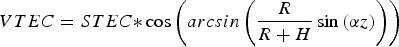 $$VTEC = STEC {\ast} \cos \left( {arcsin\left( {\displaystyle{R \over {R + H}}\sin \left( {\alpha z} \right)} \right)} \right)$$
where z is the satellite's zenith distance at the receiver; R is the mean radius of the Earth, and α is a correction factor. Best fit of the MSLM with respect to the JPL Extended Slab Model (ESM) mapping function is achieved at H = 506·7 km and α = 0·9782, when using R = 6371 km and assuming a maximum zenith distance of 80° (Dach et al., Reference Dach, Hugentobler, Fridez and Meindl2007).
The VTEC can be modelled on a regional scale as a function E(β, s) of the geographic latitude (β) and the sun-fixed (s) longitude of the IPP, respectively. The regional VTEC is expressed as a spherical harmonic expansion, which takes the form (Schaer, Reference Schaer1999):
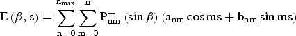 $${\rm E}\left( {{\rm \beta}, {\rm s}} \right) = \mathop \sum \limits_{{\rm n} = 0}^{{\rm n}_{{\rm max}}} \mathop \sum \limits_{{\rm m} = 0}^{\rm n} {\rm P}_{{\rm nm}}^ - \left( {\sin {\rm \beta}} \right)\left( {{\rm a}_{{\rm nm}} \cos {\rm ms} + {\rm b}_{{\rm nm}} \sin {\rm ms}} \right)$$
where n max is the maximum degree of the spherical harmonic expansion;  $P_{nm}^ - $ are normalised associated Legendre functions of degree n and order m; a nm and b nm are the unknown coefficients of spherical harmonics.
Substituting Equations (4) and (5) into Equation (6), the ionospheric spherical harmonic model can be expressed as:
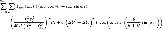 $$\eqalign{& \mathop \sum \limits_{n = 0}^{n_{max}} \mathop \sum \limits_{m = 0}^n P_{nm}^ - \left( {\sin \beta} \right)\left( {a_{nm} \cos ms + b_{nm} \sin ms} \right) \cr & \quad= \left( {\displaystyle{{\,f_1^2 f_2^2} \over {40 \!\cdot\! 3\left( {\,f_1^2 - f_2^2} \right)}}} \right)\left[ {P_4 + c\; \left( {\Delta b^S + \Delta b_r} \right)} \right]{\ast}\; \cos \left( {arcsin\left( {\displaystyle{R \over {R + H}}\sin \left( {\alpha z} \right)} \right)} \right)} $$
where a nm, b nm, Δb s and Δb r are the unknown parameters to be computed.
In order to separate the DCBs of the satellites and receivers, an additional constraint must be used. It assumes that the sum of satellite DCBs is zero (Equation (8)).
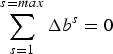 $$\mathop \sum \limits_{s = 1}^{s = max} \Delta b^s = 0$$
3. METHODOLOGY
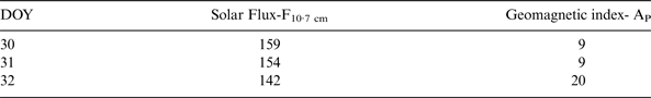
A regional network consisting of 60 IGS and EUREF reference stations in Europe has been used to develop the Real-Time Regional Ionospheric Model (RT-RIM) (Figure 1). The station distribution represents different latitudes in order to reflect different ionospheric characteristics. GPS observations for three successive days (Day Of Year (DOY) 30, 31 and 32 in 2015) have been downloaded (BKG, 2015). Table 1 shows the radio flux at 10·7 cm wavelength (F10·7) index (NICT-SWIC, 2015) and geomagnetic planetary (AP) index (GFZ, 2015) in the three days that represent the solar and geomagnetic activity, respectively. As shown in Table 1, the solar activity is high in the three days, while the geomagnetic activity is unsettled in the first two days and active in the third day.

Figure 1. Station distribution.
Each observation file has a 24-hour time span and a 30-second time interval. The observation files have been processed using the Bernese 5.2 software package using the PPP module. In order to produce the RT-RIM, the IGS-RTS satellite orbit and clock products (IGS-RTPP, 2015) have been used and then have been converted into the Bernese formats. The un-differenced code observations have been smoothed. In the parameters estimation process, the effective height has been selected to be 450 km. In addition, a maximum degree and order equal to six of the spherical harmonic expansion has been selected with a 15-minute interval. A group of 49 coefficients of the spherical harmonic model has been obtained for each time epoch. Thereafter, to extract the VTEC maps a spatial and temporal resolution of 1° × 1° and 15 minutes, respectively, have been selected. Figure 2 shows the flow chart of the proposed steps for the RT-RIM and its evaluation procedure.
Figure 2. Flow chart of the proposed RT-RIM.
4. RESULTS AND ANALYSIS
In order to evaluate the developed RT-RIM, GPS observations from another set of stations (Figure 1 in red) were processed using Natural Resources Canada (NRCan) GPSPace PPP software. The GPS observation time window was six hours starting from 12 UT. The tested stations were selected to represent different latitudes (Table 2). The IGS–RTS precise orbit and clock products were used to account for the satellite orbit and clock errors, respectively. For the modernised C1/P2 receivers, the data was corrected using the P1-C1 DCBs in order to be consistent with the satellite clock corrections convention. In addition, the tropospheric delay was modelled using the Hopfield model with the Neil mapping function. The PPP positioning accuracy was calculated and compared with the un-differenced dual frequency ionosphere-free and single-frequency using the combined rapid IGS-GIM model. For the PPP positioning processes of the dual frequency ionosphere-free and the IGS-GIM model, the rapid IGS precise satellite orbit and clock products (IGS, 2015) were used to remove the satellite orbit and clock errors.
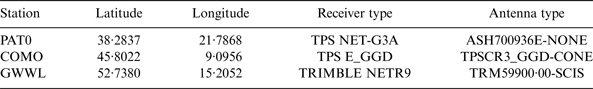
Table 2. Tested stations characteristics.
Similar convergence times are obtained for each station in the three days. For illustration purposes, only the convergence times for station GWWL, PAT0 and COMO on DOY 30, 31 and 32, respectively are shown in Figure 3 as examples. It is seen that the RT-RIM accelerates the convergence time with respect to the IGS-GIM model.
Figure 3. PPP convergence time.
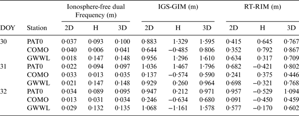
The computed PPP station coordinates were compared with those of the EUREF final weekly counterparts. Table 3 summarises the mean difference for the horizontal, height and 3D components for the three examined stations.
Table 3. Positioning accuracy differences.
As given in Table 3, the PPP positioning accuracy is improved when the RT-RIM is used, in comparison with IGS-GIM model. For station PAT0, the 2D positioning accuracy obtained from the RT-RIM is improved from 0·833 m to 0·415 m and from 1·036 m to 0·682 m on DOY 30 and 31, respectively. The accuracy of the height component is also improved from 1·329 to 0·645 m and from 1·467 m to 0·421 m on DOY 30 and 31, respectively. An exception is the results on DOY 32. For station COMO, the RT-RIM horizontal positioning accuracy is better than that of the IGS-GIM, where it is changed from 0·644 m to 0·352 m and from 0·246 m to 0·091 m in DOY 30 and 32, respectively. An exception is the results on DOY 31. The error in the height component is reduced from 0·574 m to 0·375 m and from 0·634 m to 0·450 m in DOY 31 and 32, respectively. An exception is the results on DOY 30. For station GWWL, the 2D positioning accuracy of the RT-RIM is also superior to that of the IGS-GIM model, where it is improved from 0·956 m to 0·634 m, from 0·929 m to 0·698 m and from 1·068 m to 0·577 m on DOY 30, 31 and 32, respectively. In addition, the error in the height component is reduced from 1·296 m to 0·317 m and from 1·161 m to 0·17 m on DOY 30 and 32, respectively. An exception is the results on DOY 31.
Figure 4 shows the horizontal and 3D PPP accuracy obtained through the RIM, in comparison with those of the un-differenced ionosphere-free dual frequency and IGS-GIM models for the three examined stations on DOY 30, 31 and 32, respectively. It can be seen that the obtained 3D positioning accuracy is improved when the RIM is used, in comparison with the IGS-GIM model. For instance, the 3D accuracy for station PAT0 is improved from 1·595 m to 0·767 m and from 1·796 m to 0·802 m on DOY 30 and 31, respectively. For station COMO, the 3D error is decreased from 0·590 m to 0·446 m and from 0·680 m to 0·459 m on DOY 31 and 32, respectively. The 3D positioning accuracy is also improved for station GWWL, where it is reduced from 1·610 m to 0·709 m, from 0·964 m to 0·768 m and from 1·578 m to 0·602 m on DOY 30, 31 and 32, respectively.
Figure 4. 2D and 3D positioning accuracy.
It is seen that in three cases the positioning accuracy obtained from the IGS-GIM model is slightly better than the RT-RIM, this is because the ionospheric delay value extracted from the IGS-GIM is more accurate than the one extracted from the RT-RIM, where the IGS-GIM is a combination of four analysis centres with different ionosphere modelling methods.
Based on the previous results, it can be concluded that the RT-RIM typically improved the positioning accuracy and convergence time by about 40%, 55% and 40% for the horizontal, height and 3D components respectively in comparison with the IGS-GIM.
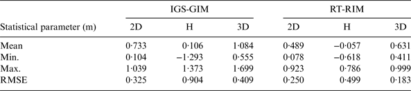
Table 4 outlines the statistical parameters, including the mean, maximum, minimum and root mean square error (RMSE) values for the positioning accuracy of the single-frequency PPP obtained through the IGS-GIM and the RT-RIM, in comparison with the ionosphere-free dual frequency solution. The results show that the positioning accuracy obtained from the RT-RIM is more accurate than that of the IGS-GIM model.
Table 4. Statistical analysis for the positioning accuracy.
5. CONCLUSION
In this study, a real-time regional ionospheric model (RT-RIM) using the IGS-RTS precise satellite orbit and clock products has been developed. GPS observations from 60 IGS and EUREF reference stations over Europe have been processed using the Bernese 5.2 PPP module. The developed model has spatial and temporal resolution of 1° × 1° and 15 minutes, respectively. In order to evaluate the RT-RIM, the PPP convergence time and positioning accuracy for another set of stations over three consecutive days under high solar activity and one of them under active geomagnetic activity, have been estimated and compared with those of the IGS-GIM and ionosphere-free dual frequency counterparts. The findings show that the developed RT-RIM speeds up the convergence time. In addition the overall positioning accuracy has improved, under the mid-latitude region, typically by about 40%, 55% and 40% for the 2D, height and 3D components, respectively, with respect to the IGS-GIM counterpart.