


1. Introduction
Rigid foils that undergo a periodic rotational pitch and/or transverse heave exhibit an exceptional tendency to self-propel unidirectionally (Alben & Shelley Reference Alben and Shelley2005; Spagnolie et al. Reference Spagnolie, Moret, Shelley and Zhang2010; Zhang, Liu & Lu Reference Zhang, Liu and Lu2010; Alben et al. Reference Alben, Witt, Baker, Anderson and Lauder2012; Zhu, He & Zhang Reference Zhu, He and Zhang2014; Deng & Caulfield Reference Deng and Caulfield2016; Verma et al. Reference Verma, Novati, Noca and Koumoutsakos2017; Das, Shukla & Govardhan Reference Das, Shukla and Govardhan2019; Lin, Wu & Zhang Reference Lin, Wu and Zhang2021). This tendency emerges as the thrust produced from a sufficiently intense prescribed harmonic excitation surmounts the hydrodynamic resistance to the foil's motion. At a mean self-propelling state, a precise balance between the mean thrust and average drag is established. This balance naturally leads to a relation between the mean self-propelling speed and the imposed kinematics and is commonly expressed in the form of a non-dimensional Strouhal number–Reynolds number dependence (Triantafyllou et al. Reference Triantafyllou, Hover, Techet and Yue2005; Gazzola, Argentina & Mahadevan Reference Gazzola, Argentina and Mahadevan2014; Smits Reference Smits2019). For a typical self-propelled flapping foil state, the Strouhal number  $St = f A/\bar {u}_p$ and the Reynolds number
  $Re = \bar {u}_p c/\nu$ represent the normalized forcing frequency and propulsive speed, respectively. Here
  $\bar {u}_p$,
  $f$,
$f$,  $A$,
$A$,  $c$ and
  $\nu$ denote the mean forward speed (an overbar indicates time average), excitation frequency, peak-to-peak trailing edge excursion, foil's chord length and kinematic viscosity of the fluid medium, respectively.
The prescribed kinematics have a direct bearing on the trailing edge excursion  $A$ and, therefore, the Strouhal number. It is then reasonable to hypothesize that the
  $St$-
$St$- $Re$ relationship will exhibit significant variations across the diverse range of self-propelling states that flapping foils with distinct imposed kinematics display. Counterintuitively however, the
  $St$-
$St$- $Re$ relationship has been shown to possess a remarkable universal character. Specifically, early investigations have shown that the range of Strouhal numbers over which swimming fishes and flying birds cruise is exceptionally narrow (
 $0.2 \leq St \leq 0.35$, see Taylor, Nudds & Thomas (Reference Taylor, Nudds and Thomas2003), Eloy (Reference Eloy2012) and review articles by Triantafyllou et al. (Reference Triantafyllou, Hover, Techet and Yue2005) and Smits (Reference Smits2019). Similar observations have been made in the recent work of Gazzola et al. (Reference Gazzola, Argentina and Mahadevan2014) wherein a balance between the thrust, hypothesized to arise from the fluid's inertial reaction to lateral body motion, and the skin friction drag from a turbulent boundary layer has been shown to desirably yield a constant Strouhal number, in agreement with the observations spanning a wide range of natural swimmers. The narrow range
  $0.2 \leq St \leq 0.35$ coincides with the range of Strouhal numbers over which high-
 $Re$ oscillating foils produce thrust at a peak propulsive efficiency (Triantafyllou, Triantafyllou & Grosenbaugh Reference Triantafyllou, Triantafyllou and Grosenbaugh1993). The foregoing similarity in the range of
  $St$ for undulatory locomotion and high efficiency thrust generation from oscillating foils is of substantial significance with wide-ranging implications. Notably, the similarity in the range of
  $St$ justifies analysis of undulatory locomotion from a global unified viewpoint and lends support to the use of relatively simple foil-like flapping states as a model system to systematically investigate much more complex self-propelling states associated with undulating natural swimmers.
The  $St$-
$St$- $Re$ relationship is fundamentally dynamical and arises naturally from a balance between a time-averaged thrust generated from body undulations and a viscous resistance to the forward motion. Its simple dynamical origin has an undeniable appeal. Nonetheless, a
  $St$-
$St$- $Re$ relation based dynamical viewpoint remains detached from the energetics of self-propulsion. The energetic cost of locomotion is often the single most important limiting constraint that determines viability of artificial locomotors and survivability of natural swimmers. A meaningful quantification of the energetic cost of locomotion is therefore central to any unified framework of self-propulsion hydrodynamics. Attempts have been made to link the narrow range of Strouhal numbers to an optimality in the energetics of the wake vorticity distribution across self-propelled organisms and thrust producing flapping foils (Triantafyllou et al. Reference Triantafyllou, Triantafyllou and Grosenbaugh1993). However, the momentumless wakes associated with self-propelling bodies are distinct from the excess-momentum wakes associated with thrust-generating tethered foils. Moreover, recent works suggest that the optimal wake energetics are more likely a consequence rather than a cause for efficient propulsion (Arbie, Ehrenstein & Eloy Reference Arbie, Ehrenstein and Eloy2016). The implication of a generality in the
  $St$-
$St$- $Re$ relation on the energetic cost of self-propulsion is therefore not quite apparent.
Here, we probe in detail the implications of a generality in the  $St$-
$St$- $Re$-relationship on the locomotory energetics and thrust generation mechanics of differentially constrained self-propelled pitching foils. Through detailed simulations and in-depth analysis of self-propelled pitching foils with distinct translational restraints, we demonstrate how a difference in the kinematic constraints leads to a profound disparity in the thrust generation mechanics. Notwithstanding this disparity, we find convergence to surprisingly similar
  $St$-
$St$- $Re$ power laws over an appropriate parametric space characterized by large reduced frequencies (reduced frequency
  $k = {\rm \pi}fc/\bar {u}_p$). Specifically, we find that the
  $St$-
$St$- $Re$ relations for the dissimilarly constrained flapping foil states are generally quite distinct and prescribed kinematics dependent. However, for sufficiently large reduced frequencies, these distinct relations converge to similar power laws with a unified scaling exponent. Most importantly, we find that the input power requirement is extremely sensitive to the translational restraints. Hence, strikingly divergent, far from universal trends for the energetic cost of locomotion are obtained for self-propelled flapping foil states that are governed by a unified
  $St$-
$St$- $Re$ relationship.
Our investigation is centred around self-propelled foils that pitch either in isolation or in combination with an induced passive heave. Configurations similar to ours but consisting of tethered foils undergoing pitch and heave in a uniform cross-flow have been extensively scrutinized in the recent past (see the review by Smits Reference Smits2019). Much of the current understanding of a convergence in the  $St$-
$St$- $Re$ dependence is based on the idea of a balance between the predominantly viscous resistance to locomotion from a laminar or turbulent boundary layer, and a counterbalancing thrust conjectured to arise principally from the fluid's inertial reaction to the periodic transverse motion. Our analysis supports a significant departure from this popular view in that a convergence to a unified
  $St$-
$St$- $Re$ power law occurs only in the large reduced frequency limit. It is only in this large reduced frequency limit that the thrusts generated from distinct leading edge suction and added mass related mechanisms assume a considerably simpler and familiar, forcing frequency and amplitude squared dependent form. The identification of this distinction in the origin of thrust and its non-trivial implications on the energetic cost of locomotion distinguish our work from the earlier ones. Our present analysis focuses exclusively on self-propelled pitching foils endowed with varying levels of translational freedom. Nonetheless, given the morphological and dynamical similarity between swimming fish and typical foils (Webb Reference Webb1975; Triantafyllou et al. Reference Triantafyllou, Hover, Techet and Yue2005; Lucas, Lauder & Tytell Reference Lucas, Lauder and Tytell2020), we anticipate that the distinction in thrust generation mechanics and the extreme sensitivity of energetics to the locomotion-enabling kinematics will be observed over a wide spectrum of rigid and flexible flapping foil self-propulsion and undulatory biolocomotion.
2. Free and restrained self-propelled foil configurations
We analyse three distinct self-propelled foil configurations, each consisting of a neutrally buoyant, rigid and homogeneous NACA0012 airfoil that is pitched about its quarter chord in a quiescent incompressible fluid of density  $\rho$ and dynamic viscosity
  $\mu$. The instantaneous angular position of the foil is given by
  $\theta = \theta _0 \sin (2 {\rm \pi}f t)$, where
  $f$ and
  $t$ denote the frequency of the imposed rotational pitch and time, respectively. We define the inline
  $x$ and the transverse
  $y$ directions along and perpendicular to the foil's chord when the foil is at its mean position, respectively. We denote the coordinates of the pivot point located at the quarter chord by
  $(x_p,y_p)$.
The three configurations are distinguished by the translational degrees of freedom endowed to the self-propelling foil. In a bidirectionally free (BF) configuration we prescribe only the rotational pitch and allow the foil to translate freely in response to the unsteady thrust/drag and lift forces. In the BF configuration we therefore determine the foil's translational motion (forward surge and transverse heave) from the total force (thrust/drag and lift) exerted on it. The unidirectionally free (UF) configuration is similar to the BF configuration except that we prevent a transverse heave motion altogether by imposing a restraint  $y_p(t) \equiv 0$. Thus, in the UF configuration we prescribe a harmonic rotational pitch and impose a zero transverse motion while determining the foil's forward surge from the total thrust force exerted on it.
For completeness, we consider a third steered (S) configuration wherein we impose a harmonic rotational pitch about the pivot point while constraining it to undergo a uniform rectilinear motion in such a way that the cycle-averaged drag (or thrust) force exerted on the foil vanishes identically. In the S configuration therefore, the foil is towed at a constant forward speed so that  $\dot {x}_p$ is thus a constant and
  $y_p(t) \equiv 0$, while the foil is pitched such that the cycle-averaged drag/thrust force vanishes identically. Owing to Galilean invariance, the configuration S is equivalent to and reminiscent of the commonly investigated canonical configuration consisting of uniform flow past a foil that is pitched sinusoidally about its quarter chord (Das, Shukla & Govardhan Reference Das, Shukla and Govardhan2016; Floryan et al. Reference Floryan, Van Buren, Rowley and Smits2017). The arrangement is such that the foil's mean chordwise direction is aligned with the free stream. In this set-up, for fixed pitching amplitude
  $\theta _0$ and a given uniform free stream
  $u_{p}$, the hydrodynamic force exerted on the foil depends strongly on the pitching frequency. Specifically, for pitching frequencies below a critical frequency
  $f$, the foil experiences a net drag force. In contrast, a mean thrust is exerted on the foil when the forcing frequency exceeds
  $f$. Precisely when the frequency of the imposed pitch equals
  $f$, a mean self-propelling state is established. In this mean self-propelling state, the cycle-averaged drag force exerted on the foil vanishes identically (as does the cycle-averaged thrust force generated from the foil's pitching motion). The frequency
  $f$ associated with this mean self-propelling state is unique in the sense that for a given combination of
  $\theta _0$ and
  $u_{p}$, the self-propelling state is achieved only when the frequency of the imposed pitch equals
  $f$. Therefore, in all the three S, UF and BF configurations,
  $u_p = \dot {x}_p$ and
  $f$ are interdependent.
In all the three configurations, we set an initial state that corresponds to a foil pitched impulsively in a quiescent fluid. The foil's pivot is located initially at the origin. We solve for the foil's position and velocity at subsequent times by computing its response to the hydrodynamic forces exerted on it. To this end, we rely on a high fidelity Lagrangian viscous vortex particle method (Cottet & Koumoutsakos Reference Cottet and Koumoutsakos2000; Eldredge Reference Eldredge2007), the details and validation tests can be found in our previous works (Das et al. Reference Das, Shukla and Govardhan2016, Reference Das, Shukla and Govardhan2019).
In both the BF and UF configurations, the foil accelerates initially and eventually attains a self-propelled state corresponding to a time-invariant cycle-averaged forward speed. Left frames of figure 1 illustrate this process for  $\theta _0 = 5^{\circ }$ and a frequency that results in a forcing Reynolds number,
  $Re_f = f A_f c/\nu = 310$, based on the maximum pitching speed at the trailing edge and the foil's chord length
  $c$ as the characteristic velocity and length scales. Here,
  $A_f = 1.5c \sin \theta _0$ denotes the trailing edge excursion due to the imposed rotational pitch. Thus,
  $A=A_f$ in UF and S configurations. However, owing to a finite induced passive heave,
  $A$ differs from
  $A_f$ in the BF configuration.

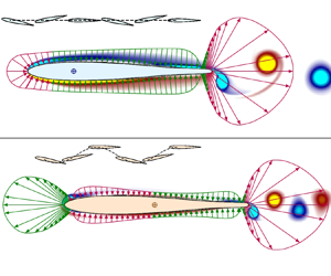
Figure 1. The forward (a) and transverse (d) velocity components, moment (b) and power (e) as a function of time for the BF (orange), UF (cyan) and S (blue) foils. (c,f) Mean surface pressure distribution over the UF/S (c) and BF (f) foils. Red and green arrows distinguish the drag-producing and thrust-generating pressure distributions, respectively. Dark circle labelled E denotes the effective pivot point (cycle-averaged centre of rotation); E coincides with the quarter chord for a UF/S foil. For a BF foil, E is determined from the combination of imposed pitch and the induced passive heave motion, and lies approximately at mid-chord. The pressure contribution to the thrust switches sign in the vicinity of E. Translucent background depicts the instantaneous vorticity distribution in the respective configurations.
The top left frame of figure 1 depicts the temporal evolution of the foil's forward and transverse velocity components  $u_p = \dot {x_p}$ and
  $v_p = \dot {y_p}$, where a dot denotes time derivative, in each of the three configurations. In the S configuration a mean self-propelling state is established at a towing speed that corresponds uniquely to the prescribed pitch. This unique towing speed overlaps perfectly with the mean forward speed of a UF foil. The moment
  $M$ and the input power
  $P$ per unit span (
 $P = -M\dot {\theta } - F_x\dot {x_p} - F_y\dot {y_p}$,
  $F_x$ and
  $F_y$ being the instantaneous thrust and lift forces per unit span) in the S and UF configurations are remarkably similar as well, despite the presence of significant inline oscillations (fluctuations in
  $u_p$) in the latter. The insensitivity of the foil's dynamics to the fluctuations in
  $u_p$ is commensurate with the insensitivity of the propulsive attributes of thrust-generating foils to the streamwise oscillations introduced in an otherwise uniform incoming flow (Van Buren et al. Reference Van Buren, Floryan, Wei and Smits2018).
The foil's dynamics in the UF and BF configurations differ strikingly. A UF foil accelerates faster than a BF foil, attains a mean self-propelling state in far fewer cycles and exhibits pronounced inline fluctuations. Crucially, the foil's mean forward speed in the UF configuration is over three-fold higher than in the BF configuration. In the UF configuration  $v_p \equiv 0$, as the translational motion in the transverse direction is forbidden by the constraint
  $y_p(t) = 0$. The BF foil exhibits prominent transverse oscillations, the corresponding fluctuations in
  $v_p$ are comparable to
  $\bar {u}_p$. Its transverse velocity component
  $v_p$ settles rather rapidly exhibiting no significant cycle-to-cycle variations right from the start. Notably,
  $v_p$ exhibits a cyclic variation that except for being completely out-of-phase is exactly analogous to the sinusoidal variation of the imposed rotational pitch. An instantaneous, direct correspondence between the induced passive heave and the imposed rotational pitch is indicative of the inviscid origin of the foil's transverse motion. The moment and power for BF and UF configurations differ strikingly, as evident from the middle frames of figure 1. Both
  $M$ and
  $P$ are however of similar functional form and exhibit a periodic temporal variation. The instantaneous cycle-to-cycle invariance of
  $M$ and
  $P$ points to their inviscid origin as well.
The out-of-phase passive heave of a BF foil counteracts the influence of imposed pitch, effectively reducing the trailing edge excursion and transverse speed. Consequently, the size and the intensity of the vortices shed into the wake of a BF foil are appreciably lower, as clearly evidenced from the right frames of figure 1. The vorticity distributions in the UF and S configurations are very nearly indistinguishable and have been depicted through a single top right frame in figure 1. Understandably, a similarity in foil dynamics in the UF and S configurations translates into a similarity in the vorticity distribution.
The disparities in the initial acceleration and the mean forward speed to which the UF and BF foils eventually settle are a direct consequence of a dissimilarity in the thrust generation mechanics. This dissimilarity is clearly evidenced from the striking contrast in the cycle-averaged pressure distribution on the BF and UF self-propelled foils (right frames of figure 1). The transverse heave of a BF foil results in a relatively large effective angle between the foil and the direction of locomotion ( $x$ direction). The periodic variation in the effective angle of attack alters the pressure distribution in such a way that a sharp drop in the mean pressure is encountered at the foil's leading edge. The thrust generated from this reduction in mean pressure (the so-called leading edge suction mechanism, Garrick (Reference Garrick1937)) facilitates propulsion of a BF foil. Owing to a significantly diminished leading edge excursion, no such drop is evidenced in a UF configuration. Consequently, the inertial reaction of the fluid is principally responsible for self-propulsion of a UF foil. This contrast in the mechanics of thrust production is quantitatively established through a minimal model for self-propelled foils in the forthcoming § 3.
3. The  $St$-$Re$ relationship and the drag–thrust balance


To link the mean self-propelling speed to the prescribed rotational pitch, we perform runs over a wide range of forcing Reynolds numbers ( $10\leq Re_f \leq 1000$) and angular amplitudes
  $5^\circ \leq \theta _0 \leq 16^\circ$ for each of the three configurations. Our principal observations deduced in the last section for the specific case of
  $\theta _0 = 5^{\circ }$ and
  $Re_f = 310$ generalize to other
  $Re_f$ and
  $\theta _0$ as well. Specifically, at each
  $Re_f$ and
  $\theta _0$, the mean self-propelling speeds attained in the UF and S configurations overlap and consistently exceed the mean self-propelling speed attained in the BF configuration by over two folds.
We next express the dependency of  $\bar {u}_p$ on the key kinematic parameters through the
  $St$-
$St$- $Re$ relationship. For fair comparison, we define the Strouhal number
  $St = fA/\bar {u}_p$ based on the actual trailing edge excursion as the characteristic length scale. As noted earlier,
  $Re = \bar {u}_pc/\nu$. Thus, owing to an explicit dependence on
  $\bar {u}_p$, both
  $Re$ and
  $St$ are in fact output quantities, the forcing Reynolds number
  $Re_f$ being the key input quantity. In figure 2 we depict the
  $St$-
$St$- $Re$ dependence for all our runs spanning the entire parametric space of
  $Re_f$ and
  $\theta _0$ in the BF, UF and S configurations. We observe an expected near-perfect overlap in the
  $St$-
$St$- $Re$ relation for the UF and S configurations. Crucially, we find a convergence in the Strouhal number's dependence on the Reynolds number in that
  $St \sim Re^{n}$, where the scaling exponent
  $n = -0.375$ is invariant across the UF, BF and S configurations. The emergence of a power-law scaling was reported in our earlier, comparatively limited parametric space (
 $\theta _0 = 5^{\circ }$) investigation of the S (Das et al. Reference Das, Shukla and Govardhan2016) and BF (Das et al. Reference Das, Shukla and Govardhan2019) configurations.

Figure 2. The  $St$-
$St$- $Re$ relation for the BF, UF and S configurations. Discrete points indicate simulation results. Theoretical prediction from the drag–thrust balance
  $\bar {C}_T(k,St) = \bar {C}_D(St,Re)$ with
  $\bar {C}_T$ from (3.3) and
  $\bar {C}_D = \gamma \sqrt {St}Re^{-0.56}$, is shown using thin solid lines. Thick solid lines depict
  $\theta _0$-independent power law that is obtained in the limit of large reduced frequencies (
 $k \gg 1$). The drag-determining constant
  $\gamma = 24$ over the entire parametric space and across the three configurations.
We note here that our scaling exponent  $n = -0.375$ differs from the exponent of
  $-0.25$ reported in the work of Gazzola et al. (Reference Gazzola, Argentina and Mahadevan2014). As mentioned in our previous work (Das et al. Reference Das, Shukla and Govardhan2016), a disparity in the set-ups analysed is a likely reason for the aforementioned difference between the scaling exponents. We investigate pure rigid body motions that arise from a combination of the free translation and prescribed time-periodic rotation. In contrast, Gazzola et al. (Reference Gazzola, Argentina and Mahadevan2014) investigate biolocomotion wherein a lateral motion induced reduction in boundary layer thickness could potentially be suppressed through travelling-wave-like undulatory motion of flexible tails. Nevertheless, our scaling exponent
  $n = -0.375$ is in excellent agreement with the power-law fit of
  $-0.4$ reported in the recent independent work on BF foils by Lin et al. (Reference Lin, Wu and Zhang2021). Notably, using
  $St Re = Re_f$, the
  $St$-
$St$- $Re$ power law can be recast into an equivalent form
  $Re \sim Re_f^{1.6}$, where the scaling exponent of
  $1.6$ deduced from our runs is in excellent agreement with the exponent of
  $5/3$ reported in Lin et al. (Reference Lin, Wu and Zhang2021). Furthermore, Lin et al. (Reference Lin, Wu and Zhang2021) observe that the power-law relationship of the form
  $St \sim Re^{-0.4}$ (equivalent to
  $Re \sim Re_f^{5/3}$) fits the locomotory characteristics of freely translating heaving foils investigated by Alben & Shelley (Reference Alben and Shelley2005) and Hu & Xiao (Reference Hu and Xiao2014), as well as those of several natural aquatic swimmers (see figure 6 in Lin et al. Reference Lin, Wu and Zhang2021). Therefore, the power law
  $St \sim Re^{-0.375}$ very likely possesses a much wider range of applicability that extends to other self-propelled flapping foil configurations and natural aquatic swimmers as well.
The trends illustrated in figure 2 unequivocally point to a generality in the scaling exponent  $n$ across the three configurations. The precise value of the scaling exponent
  $n$ that fits the discrete data set in figure 2 so closely has been shown to arise naturally from a balance between the mean drag coefficient
  $\bar {C}_{D} \sim \sqrt {St}Re^{-0.56}$ and the cycle-averaged thrust coefficient
  $\bar {C}_T \sim St^2$ in the configuration S (Das et al. Reference Das, Shukla and Govardhan2019) as
 \begin{equation} \bar{C}_T \sim St^2 \quad \mbox{and} \quad \bar{C}_D \sim \sqrt{St}Re^{{-}0.56} \quad \mbox{so that}\ \bar{C}_T = \bar{C}_D \Rightarrow St \sim Re^{{-}0.375}, \end{equation}
where  $\rho \bar {u}_p^2 c/2$ has been used for non-dimensionalization of thrust/drag. The specific form
  $\bar {C}_{T} \sim St^2$ arises from a
  $(fA)^2$ dependence of the inertial thrust conjectured to originate from the fluid's reaction to the transverse foil motion (Gazzola et al. Reference Gazzola, Argentina and Mahadevan2014). The expression for the cycle-averaged drag coefficient used in (3.1) follows directly from the Bone–Lighthill boundary layer thinning hypothesis (Lighthill Reference Lighthill1971) for enhanced viscous resistance experienced by a swimming body that undergoes significant lateral movement perpendicular to itself (Das et al. Reference Das, Shukla and Govardhan2016). Specifically, the cycle-averaged drag coefficient in (3.1) is deduced from the general expression
  $\bar {C}_D \sim \sqrt {St}C_{D0}$, where a
  $\sqrt {St}$ dependence accounts for the boundary layer thinning due to transverse body motion (Ehrenstein, Marquillie & Eloy Reference Ehrenstein, Marquillie and Eloy2014). The term
  $C_{D0}$ represents the drag coefficient associated with a similar body that is held stationary in a uniform cross-flow. Specifically for a NACA0012 foil,
  $C_{D0} = 5.91Re^{-0.56}$ (Das et al. Reference Das, Shukla and Govardhan2016). Computational results confirming the Bone–Lighthill boundary layer thinning hypothesis for uniform flow past two- and three-dimensional finite-span plates undergoing significant time-oscillatory wall-normal motion have appeared in Ehrenstein & Eloy (Reference Ehrenstein and Eloy2013) and Ehrenstein et al. (Reference Ehrenstein, Marquillie and Eloy2014). Clearly, the scaling exponent
  $n$ conforms to the
  $St$-
$St$- $Re$ discrete data set for the UF and BF configurations equally well. Hence, a heuristic extension of the foregoing arguments to UF and BF self-propelled foils is particularly tantalizing.
A generalization of the above arguments to a UF configuration is justified given the insensitivity of UF foil's dynamics to inline oscillations. Generalization to a BF configuration is however dubious owing to the stark disparity in the mean pressure distribution, the principal source of thrust, over the BF and UF/S foils (see § 2 and figure 1). Furthermore, the  $St$-
$St$- $Re$ relationship for a BF configuration is discernibly offset from the St-Re relationship for the UF and S configurations (figure 2). Unlike the scaling exponent, this offset can not be explained from a straightforward generalization of the scaling arguments from the foregoing paragraph. We emphasize here that the offset is not a consequence of the use of actual trailing edge excursion in the definition of
  $St$. The offset is in fact enhanced with a switch to the forcing amplitude
  $A_f$ based definition of the Strouhal number (
 $A/A_f \approx 0.67$ as shown in the forthcoming analysis).
To unravel the reasons underlying the offset in the  $St$-
$St$- $Re$ relation, we analyse the mechanics of thrust production in UF and BF configurations by developing a minimal model for self-propelled foils wherein the pitch induced passive heave is either prevented (UF configuration) or determined by coupling the BF foil's transverse motion to the lift force deduced from the linear theory (Garrick Reference Garrick1937; von Kármán & Sears Reference von Kármán and Sears1938; Fernandez-Feria Reference Fernandez-Feria2016). The complete details of our rigorous linear theory based modelling approach for prediction of transverse foil dynamics and thrust generation mechanics associated with BF/UF configurations are provided in Appendix A. The analysis yields the following theoretical estimate for the transverse dynamics of the foil's pivot point (see Appendix A.1):
 \begin{equation} \tilde{y}_p = \left(A_f/3\right)\sqrt{\left(b_1^2+b_2^2\right)/\left(a_1^2+a_2^2\right)}, \quad \phi_h = \tan^{{-}1}\left(b_2/b_1\right) -\tan^{{-}1} \left(a_2/a_1\right). \end{equation}
Here  $\tilde {y}_p$ and
  $\phi _h$ denote the amplitude and phase with respect to the prescribed pitch (
 $y_p = \tilde {y}_p \sin (2{\rm \pi} f t + \phi _h)$),
  $a_1 = -k^2 - 2 k G$,
  $a_2 = 2 k F$,
  $b_1 = k^2 + 2 k G - 2 F$,
  $b_2 = -2 k F - k - 2 G$. Here reduced frequency
  $k={\rm \pi} f c/\bar {u}_p$ and Theodorsen function
  $C(k) = F(k) + iG(k)$.
In figure 3 we compare the theoretical predictions from (3.2a,b) with the heave amplitude and phase obtained from the simulations. The  $k$-dependence in the heave amplitude and phase given by (3.2a,b) arises principally from a Coriolis-like term that is significant only at low reduced frequencies and is
  $90^{\circ }$ phase offset with respect to
  $\theta$. Without this Coriolis term, the foil's transverse motion is
  $k$-independent and arises solely from the added mass effects. Thus, without the Coriolis term, or equivalently when
  $k \gg 1$,
  $\tilde {y}_p \approx 0.16A_f$,
  $\phi _h = 180^{\circ }$ (shown by dotted lines in figure 3) and
  $A \approx 0.67A_f$ so that the induced heave and imposed pitch are completely out-of-phase. The dominance of the Coriolis effect at progressively lower reduced frequencies leads to an increasingly prominent passive heave that lags the imposed pitch by a monotonically decreasing phase
  $\phi _h$. The agreement between the simulation results and predictions from the linear theory based model that fully accounts for the added mass and Coriolis effects is quite remarkable over the entire parametric space of
  $\theta _0$ and
  $Re$. The agreement indicates that the BF foil's passive heave arises principally from a recoil reaction to the imposed pitch.

Figure 3. Amplitude (a) and phase (c) of the induced passive heave in the BF configuration as a function of the reduced frequency  $k$. Solid black lines depict theoretical prediction from (3.2a,b). Dashed lines depict the reduced frequency independent
  $k \gg 1$ limits.
With a reasonably accurate predictive model for transverse motion in place, we again appeal to the linear theory for an estimate of the mean thrust coefficient. For a foil undergoing simultaneous pitch and heave motions, as shown in Appendix A.2,
 \begin{equation} \bar{C}_{T}(k,St) = \bar{C}_{T}^{R} + \bar{C}_{T}^{QS}+ \bar{C}_{T}^W + \bar{C}_{T}^{LS}, \end{equation}
where the reactive (added mass related), quasi-steady, wake and leading edge suction contributions to the mean thrust coefficient are given by
 \begin{equation} \left.\begin{aligned}
\bar{C}_{T}^{R} & = {\rm \pi}^3 St^2 \alpha^2
(2\beta\cos\phi_h + 1),\quad \bar{C}_{T}^{QS}
={-}4 {\rm \pi}^3 St^2 \alpha^2 (k^{{-}2} - k^{{-}1}\beta
\sin\phi_h), \\ \bar{C}_{T}^{W} & = 4 {\rm \pi}^3 St^2
\alpha^2 \{(1 -F ) [ k^{{-}2} -
k^{{-}1}\beta\sin\phi_h ] + Gk^{{-}1} [1 + \beta
\cos\phi_h ] \}, \\ \bar{C}_{T}^{LS} & = {\rm \pi}^3
St^2\alpha^2 \{4 \beta^2 |C|^2- 4\beta [ (F
- 2|C|^2)\cos\phi_h\\ & \quad +(2k^{{-}1} |C|^2 - G) \sin\phi_h]+ (1-2 F)^2 + 4 G^2 - 4 Gk^{{-}1} + 4
|C|^2k^{{-}2}\},\\ & \quad \mbox{with}\ |C|^2=F^2+G^2,\quad \beta = 2\tilde{y}_p/( c
\theta_0). \end{aligned}\right\}
\end{equation}
\begin{equation} \left.\begin{aligned}
\bar{C}_{T}^{R} & = {\rm \pi}^3 St^2 \alpha^2
(2\beta\cos\phi_h + 1),\quad \bar{C}_{T}^{QS}
={-}4 {\rm \pi}^3 St^2 \alpha^2 (k^{{-}2} - k^{{-}1}\beta
\sin\phi_h), \\ \bar{C}_{T}^{W} & = 4 {\rm \pi}^3 St^2
\alpha^2 \{(1 -F ) [ k^{{-}2} -
k^{{-}1}\beta\sin\phi_h ] + Gk^{{-}1} [1 + \beta
\cos\phi_h ] \}, \\ \bar{C}_{T}^{LS} & = {\rm \pi}^3
St^2\alpha^2 \{4 \beta^2 |C|^2- 4\beta [ (F
- 2|C|^2)\cos\phi_h\\ & \quad +(2k^{{-}1} |C|^2 - G) \sin\phi_h]+ (1-2 F)^2 + 4 G^2 - 4 Gk^{{-}1} + 4
|C|^2k^{{-}2}\},\\ & \quad \mbox{with}\ |C|^2=F^2+G^2,\quad \beta = 2\tilde{y}_p/( c
\theta_0). \end{aligned}\right\}
\end{equation}
Here  $\alpha = A_f/(3A)$, with
  $A^2 = A_f^2 + 4\tilde {y}_p^2 + 4A_f\tilde {y}_p\cos \phi _h$. Clearly
  $\beta = 0$ for UF/S foils.
An evaluation of the above contributions in the large reduced frequency limit yields  $\bar {C}_{T} \approx \bar {C}_{T}^{R} = {\rm \pi}^3 St^2/9$ in the UF and S configurations. Here the quasi-steady, wake and leading edge suction terms contribute negligibly and the mean thrust is generated principally from the fluid's reaction to the imposed pitch (see Appendix A.3 for details). Contrastingly, in a BF configuration
  $\bar {C}_{T} \approx \bar {C}_{T}^{LS} = {\rm \pi}^3 St^2 /16$ with the rest of the terms contributing negligibly to the mean thrust coefficient (see Appendix A.4). Thus, the reaction from the fluid ceases to be a significant source of thrust and rather, consistent with the pressure distribution contrast depicted in figure 1, the thrust produced via leading edge suction mechanics self-propels a BF foil.
The reason behind the equivalence in the scaling exponent and the offset between the  $St$-
$St$- $Re$ power laws for the BF and UF configurations is now unravelled. The balance between the mean thrust coefficient from (3.3) and a cycle-averaged drag coefficient that is consistent with the Bone–Lighthill boundary layer thinning hypothesis,
 \begin{equation} \bar{C}_T(k,St) = \bar{C}_D(St,Re), \quad \mbox{where}\ \bar{C}_D = \gamma \sqrt{St}Re^{{-}0.56}, \end{equation}
 $\gamma$ being a drag-determining parameter, allows us to deduce a general
  $k$-dependent
  $St$-
$St$- $Re$ relation. This general relation is
  $\theta _0$ specific, but for sufficiently large
  $k$ (or equivalently large
  $St$), simplifies considerably to a unified
  $\theta _0$-independent power law across UF, BF and S configurations as
 \begin{equation} \bar{C}_T (k\rightarrow \infty,St) = \frac{{\rm \pi}^2 St^2}{16} \implies St = \left(\frac{16\gamma}{{\rm \pi}^2}\right)^{2/3}Re^{{-}0.375} \quad \text{for a BF foil}, \end{equation}
and
 \begin{equation} \bar{C}_T (k\rightarrow \infty,St) = \frac{{\rm \pi}^2 St^2}{9} \implies St = \left(\frac{9\gamma}{{\rm \pi}^2}\right)^{2/3}Re^{{-}0.375} \quad \text{for a UF/S foil}, \end{equation}
in the large reduced frequency limit ( $k \gg 1$).
The similarity in the scaling exponent across the three configurations is thus a direct consequence of an equivalence in the high reduced frequency scaling of the thrust coefficient ( $\bar {C}_T \sim St^2$ for
  $k \gg 1$ in UF, BF and S configurations). Importantly, the difference in the magnitude of mean thrusts (proportionality constant of
  ${\rm \pi} ^3/16$ vs
  ${\rm \pi} ^3/9$) produced in the BF and UF configurations is directly responsible for the appreciable offset in the
  $St$-
$St$- $Re$ relation. As evident from figure 2, the general
  $k$-dependent
  $St$-
$St$- $Re$ relation with just a single adjustable parameter
  $\gamma$ fits the discrete data set from our simulations reasonably well and crucially explains both the offset between the
  $St$-
$St$- $Re$ relations for BF and UF/S foils, and the divergence from the unified power law at low
  $k$. Evidently, such low
  $k$, or
  $St$, is achieved at the highest Reynolds numbers (
 $Re \gtrapprox 500$ as inferred from the inset of figure 2).
4. Energetic cost of self-propulsion
The impact of the passive heave on the energetic cost of self-propulsion is significantly more pronounced. In figure 4 we compare the mean power coefficient ( $\bar {C}_P = 2\bar {P}/(\rho \bar {u}_p^3 c)$) for all our runs over the three configurations. Owing to the form of normalization employed, the power coefficient can also be viewed as a scaled cost of transport. At low
  $Re$ (
 $Re \lessapprox 200$), the mean power coefficient for the BF configuration consistently exceeds power coefficients for UF and S configurations by a factor that varies from two to three (left frame of figure 4). The power coefficients for the UF and S configurations are expectedly in mutual agreement.

Figure 4. Mean power coefficient as a function of  $Re$ (a) and
  $St$ (b). The symbols are the same as in figure 2. The parameter
  $\zeta = 22$ is a constant across the entire parametric space.
To link  $\bar {C}_P$ and imposed kinematics, we illustrate the dependence of
  $\bar {C}_P$ on
  $St$ in the right frame of figure 4. We observe an effective convergence to a unified power law
  $\bar {C}_P \sim St^3$ across the UF, BF and S configurations. The
  $Re$-dependent disparity in the power requirement, as evidenced from the left frame of figure 4, is therefore a direct consequence of a cubic amplification of the comparatively small offset in the
  $St$-
$St$- $Re$ relation (figure 2). To self-propel at a given
  $\bar {u}_p$, a BF foil must overcome the counterproductive out-of-phase passive heave through a more intense rotational pitch (higher
  $\theta _0$ and/or
  $f$). The increase in pitching intensity significantly augments the mean energetic cost of self-propulsion.
Foregoing arguments hold reasonably well in the low  $Re$ regime wherein
  $k \gg 1$. In this case, the imposed pitch and the passive heave remain nearly out-of-phase (
 $\phi _h \approx 180^{\circ }$). The reduced frequency
  $k \gg 1$ over a majority of the parametric space, except at the highest
  $\theta _0$ and/or
  $f$. At high
  $\theta _0$ and/or
  $f$, with further increase in the pitching intensity,
  $Re$ rises whereas
  $St$ and
  $k$ diminish considerably. At sufficiently high
  $Re$, or equivalently low
  $k$, owing to the dominance of the Coriolis-like term,
  $\tilde {y}_p$ grows while
  $\phi _h$ diminishes monotonically towards
  $90^{\circ }$ (see figure 3). In this scenario, a BF foil's excursions from its instantaneous direction of motion are reduced and its cost of transport is diminished. At sufficiently low
  $k$,
$k$,  $\bar {C}_P$ for a BF foil reduces to such an extent that it is overwhelmed by the
  $\bar {C}_P$ for a UF foil. The induced passive heave thus plays a contrasting role in that it enhances locomotory performance of a BF foil at high
  $Re$ (low
  $k$), while reducing it at low
  $Re$ (high
  $k$). This contrast in the role of passive heave at low and high
  $k$ is consistent with the enhancement of thrust generated from tethered foils undergoing combined pitch and heave motions at
  $\phi _h = 90^{\circ }$, and its deterioration at
  $\phi _h = 180^{\circ }$ (Anderson et al. Reference Anderson, Streitlien, Barrett and Triantafyllou1998; Smits Reference Smits2019). Our results point to the possibility of achieving an exceptionally efficient fish-like locomotory state in a relatively simple self-propelled system. Remarkably, the induced heave in this BF self-propelled system is passive and uncontrolled and, thus, not tuned to minimize the energetic cost of locomotion.
5. Conclusions
In summary, through detailed simulations, we demonstrated that bidirectionally and unidirectionally free self-propelled pitching foils exhibit a stark distinction in the thrust generation mechanics and locomotory performance, and yet are governed by a remarkably similar  $St$-
$St$- $Re$ scaling. Our drag–thrust balance based analysis revealed a similarity in the high reduced frequency scaling of the thrust generated from the distinct propulsion-enabling mechanisms in bidirectionally and unidirectionally free configurations (leading edge suction in BF vs recoil reaction in UF) to be the principal cause of the similarity in the scaling exponent. In general, the
  $St$-
$St$- $Re$ dependence is therefore prescribed kinematics dependent, and a reduction to a previously reported, considerably simpler power-law form with a unified scaling exponent can only be expected in the large reduced frequency limit. Crucially, we established that an amplification of the offset in the
  $St$-
$St$- $Re$ relation, caused by the
  $St^3$ dependence of the scaled cost of transport, is directly responsible for the contrast between the locomotory performance of UF and BF foils.
Being the principal determinant of the scaling exponent  $n$ in the
  $St\sim {Re}^{n}$ power law, drag plays an important dynamical role in the differentially constrained configurations investigated in our work. This conclusion is consistent with the previous ones that have noted the importance of drag in dictating the optimal Strouhal number for flexible locomotion (Godoy-Diana & Thiria Reference Godoy-Diana and Thiria2018) and maximization of thrust generation efficiency from tethered flapping foils (Floryan, Van Buren & Smits Reference Floryan, Van Buren and Smits2018). Here we stress on the critical role of thrust in introducing an offset in the
  $St$-
$St$- $Re$ dependence, and through its amplification, being ultimately responsible for the large disparity in the locomotory performance of differentially constrained foils. We anticipate that this key conclusion from our work will generalize to other forms of oscillatory flapping foil propulsion and undulatory biolocomotion. Specifically, the extreme sensitivity to variations in thrust will prevail in artificial as well as natural undulatory swimmers so that any deviation from a general
  $St$-
$St$- $Re$ trend in the form of an offset or general scatter will have enormous implications for the energetic cost of locomotion.
Funding
We acknowledge support received from NVIDIA Corporation (hardware donation program) and National Supercomputing Mission of the Department of Science and Technology (runtime on cray XC-40 housed in Supercomputing Education and Research Center-Indian Institute of Science).
Declaration of interests
The authors report no conflict of interest.
Appendix A
Here we provide details of the linear theory based model for predicting the thrust generated from unidirectionally and bidirectionally free foils that are pitched about their quarter chord. A BF foil can undergo lateral heave motion in addition to its forward surge. To begin with therefore, we analyse the imposed pitch induced passive heave in a BF foil.
A.1. Model for prediction of imposed pitch induced passive heave of a BF foil
Apart from being almost out-of-phase, the transverse heave of a BF foil very nearly follows the imposed harmonic pitch. This combined with the fact that the transverse heave of a BF foil exhibits no significant cycle-to-cycle variation right from the start (as shown in figure 1) points to the inviscid origin of the induced lateral heave motion. Linear theory (Theodorsen Reference Theodorsen1935; Garrick Reference Garrick1937; von Kármán & Sears Reference von Kármán and Sears1938; Fernandez-Feria Reference Fernandez-Feria2016, Reference Fernandez-Feria2017; Mackowski & Williamson Reference Mackowski and Williamson2017) provides a natural framework for an inviscid analysis of thin foils undergoing combined pitch and heave motions. We therefore appeal to the inviscid linear theory for prediction of transverse dynamics of a BF foil.
We consider an upward linear motion and counterclockwise rotational motion of the foil to be positive. Utilizing this sign convention, the lift force per unit span, exerted on the foil, as deduced from linear theory is given by
 \begin{equation} L = \frac{{\rm \pi} \rho c^2}{4} \left(-\bar{u}_p \dot{\theta} - \ddot{y}_p + \frac{a c}{2} \ddot{\theta}\right) + {\rm \pi}\rho c \bar{u}_p C(k) Q(t), \end{equation}
where
 \begin{equation} Q(t) ={-}\bar{u}_p \theta - \dot{y}_p + \frac{c}{2} \left( a - \frac{1}{2} \right) \dot{\theta}, \end{equation}
and  $C(k) = F(k) + \textrm {i} G(k)$ is the Theodorsen function. The reduced frequency
  $k = {\rm \pi}f c/\bar {u}_p$, where
  $\bar {u}_p$ denotes the mean forward velocity of the foil with
  $a$ as the pivot location normalized with respect to the foil's half-chord length
  $c/2$. For pitching motion about the quarter chord therefore,
  $a = -1/2$. The instantaneous heave is characterized using the vertical displacement of the pivot point
  $y_p = \tilde {y}_p \exp ({\textrm {i}( 2 {\rm \pi}f t + \phi _h)})$, where
  $f$ and
  $\tilde {y}_p$ represent the frequency and amplitude of the induced passive heave. The instantaneous angular position of the foil is given by
  $\theta = \theta _0 \exp ({\textrm {i} 2 {\rm \pi}f t})$, where
  $\theta _0$ denotes the amplitude of the imposed rotational pitch. Given the insensitivity of the foil's dynamics to the inline oscillations (see § 2), we employ only the mean forward speed
  $\bar {u}_p$ in our estimate (A1) of the lift force.
The transverse heave of a BF foil is a direct consequence of the instantaneous lift force exerted on it. We therefore obtain
 \begin{equation} m\ddot{y}_{cm} = {\rm \pi}\rho c^2 \left(-\bar{u}_p \dot{\theta} - \ddot{y}_{p} + a c \ddot{\theta}/2\right)/4 + {\rm \pi}\rho c \bar{u}_p C(k) Q(t), \end{equation}
where  $m$ and
  $y_{cm}$ denote the foil's mass per unit span and the
  $y$-coordinate of its geometric centre, respectively. For small pitching angles, an assumption inherent in the linear theory, we can relate
  $y_{cm}$ to
  $y_p$ as
 \begin{equation} y_{cm} = y_p + r_{cm/p} \theta \quad \mbox{and} \quad \ddot{y}_{cm} = \ddot{y}_p + r_{cm/p} \ddot{\theta}, \end{equation}
where  $r_{cm/p}$ denotes the distance between the geometric centre and the pivot point. Substituting (A4a,b) in (A3) we obtain
 \begin{equation} m\left(\ddot{y}_{p} + r_{cm/p} \ddot{\theta}\right) = {\rm \pi}\rho c^2 \left(-\bar{u}_p \dot{\theta} - \ddot{y}_{p} + a c \ddot{\theta}/2\right)/4 + {\rm \pi}\rho c \bar{u}_p C(k) Q(t). \end{equation}
A rearrangement yields
 \begin{align} \left(m+\frac{{\rm \pi} \rho c^2}{4} \right) \ddot{y}_{p} + {\rm \pi}\rho c \bar{u}_p C(k) \dot{y}_{p} &= \left( \frac{c^2}{2} \left(a-\frac{1}{2} \right){\rm \pi}\rho \bar{u}_pC(k) - \frac{{\rm \pi} \rho c^2}{4} \bar{u}_p\right) \dot{\theta} \nonumber\\ &\quad +\left(\frac{{\rm \pi} \rho c^3 a}{8} -m r_{p/cm} \right) \ddot{\theta} - \bar{u}_p^2 {\rm \pi}\rho c C(k) \theta. \end{align}
Substitution of the specific forms for pitch and heave allows us to deduce that
 \begin{align} \tilde{y}_p = (\theta_0 c/2) \sqrt{(b_1^2+b_2^2)/(a_1^2+a_2^2)} \quad \mbox{and} \quad \phi_h = \tan^{{-}1}\left(b_2/b_1\right) -\tan^{{-}1} \left(a_2/a_1\right), \end{align}
where  $a_1 = -k^2 [1 + 4 m/({\rm \pi} \rho c^2)] - 2 k G(k)$,
  $a_2 = 2 k F(k)$,
  $b_1 = k^2 [ {8\,m r_{cm/p}/({\rm \pi} \rho c^3)} - a ] + (1 - 2a ) k G(k) - 2 F(k)$ and
  $b_2 = (2a - 1 ) k F(k) - k - 2 G(k)$.
A normalization using  $A_f = 1.5 \theta _0 c$, the trailing edge excursion due to the imposed pitch, yields the following for the non-dimensional amplitude of the transverse harmonic motion of the pivot point:
 \begin{equation} \tilde{y}^*_p = \tilde{y}_p/A_f = \tilde{y}_p/(2 r_p c \theta_0) = (1/3) \sqrt{(b_1^2+b_2^2)/(a_1^2+a_2^2)}. \end{equation}
Here  $r_p c = 0.75c$ denotes the distance between the trailing edge and the pivot point. Substituting parameters specific to a NACA0012 foil, ignoring the influence of the foil's mass
  $m$ (
$m$ ( $m/\rho c^2 = 0.08 \ll 1$), and utilizing
  $r_{cm/p} = 0.17c$ for the configuration under investigation, we obtain
  $a_1 = -k^2 - 2 k G(k)$,
  $a_2 = 2 k F(k)$,
  $b_1 = 0.5 k^2 + 2 k G(k) - 2 F(k)$ and
  $b_2 = - 2 k F(k) - k - 2 G(k)$. An expression for the trailing edge excursion of a BF foil can now be derived as
 \begin{equation} y_{te} = r_p \theta_0 c \sin (2 {\rm \pi}f t) + \tilde{y}_p \sin (2 {\rm \pi}f t + \phi_h) = A \sin(2 {\rm \pi}f t + \psi )/2. \end{equation}
Furthermore,
 \begin{align} \frac{A^2}{4} &= (r_p \theta_0 c)^2 + \tilde{y}_p^2 + 2 r_p \theta_0 c \tilde{y}_p \cos(\phi_h) \nonumber\\ &= (r_p \theta_0 c)^2 \left\{\frac{(3a_1 + 2b_1)^2 + (3a_2 + 2b_2)^2}{9(a_1^2 + a_2^2)} \right\} \nonumber\\ &\implies A = A_f \sqrt{\frac{(3a_1 + 2b_1)^2 + (3a_2 + 2b_2)^2}{9(a_1^2 + a_2^2)}}. \end{align}
We note here that our present model, developed within the rigorous framework of linear theory, is far more generic than the model developed in our previous work (Das et al. Reference Das, Shukla and Govardhan2019). Our present model fully accounts for the leading edge suction mechanics, as well as the added mass effects, and also incorporates contributions from the quasi-steady terms and the wake. Unlike the model proposed in Das et al. (Reference Das, Shukla and Govardhan2019), our present linear theory based model remains applicable over a wide range of reduced frequencies and accurately predicts the strong  $k$-dependence of the amplitude and phase of the induced passive heave in the BF configuration (see figure 3). It is worth noting that in the limit
  $k \gg 1$, the expression (A10) simplifies to
  $A \approx 2A_f/3$.
A.2. Thrust generation mechanics of UF and BF self-propelled foils
Having characterized the passive heave of a BF foil, we next extend our analysis to predict the propulsion-enabling thrust force exerted on the BF and UF foils. Here, unlike several previous works on similar configurations (Gazzola et al. Reference Gazzola, Argentina and Mahadevan2014; Das et al. Reference Das, Shukla and Govardhan2016, Reference Das, Shukla and Govardhan2019, for instance), we do not make any intrinsic assumption about the reactive origin of the thrust. Rather, the determination of the mean thrust is tightly coupled to the theoretical prediction of the lateral foil motion from the previous subsection.
The instantaneous thrust force experienced by a foil undergoing simultaneous pitch ( $\theta = \theta _0 \exp ({\textrm {i} 2 {\rm \pi}f t})$) and heave (
 $y_{p}=\tilde {y}_p \exp ({\textrm {i}(2 {\rm \pi}f t + \phi _h )})$) is given by
 \begin{equation} T =
\underbrace{\textrm{Im}(L)
\textrm{Im}(\theta)}_\textit{Normal force contribution to
thrust} + \underbrace{\frac{{\rm \pi} \rho
c}{2}\left[\textrm{Im}(S)
\right]^2}_\textit{Leading edge suction contribution
to thrust}, \end{equation}
\begin{equation} T =
\underbrace{\textrm{Im}(L)
\textrm{Im}(\theta)}_\textit{Normal force contribution to
thrust} + \underbrace{\frac{{\rm \pi} \rho
c}{2}\left[\textrm{Im}(S)
\right]^2}_\textit{Leading edge suction contribution
to thrust}, \end{equation}
where  $L$ denotes the normal force component oriented in a direction perpendicular to the foil's chord with S as the leading edge suction term. The normal force (
 $L$) and leading edge suction term (S) are given by
 \begin{align} L = \frac{{\rm \pi} \rho c^2}{4}\left(-\bar{u}_p\dot{\theta}-\ddot{y}_p + \frac{c}{2}a\ddot{\theta} \right) + c {\rm \pi}\rho \bar{u}_p Q(t) C(k) \quad \mbox{and}\quad S = \frac{1}{\sqrt{2}} \left(2 C(k) Q(t) + \frac{c}{2}\dot{\theta}\right). \end{align}
 We split the normal force into three components, the reactive (added mass related) contribution  $L^R$, the contribution from the quasi-steady circulatory part
  $L^{QS}$, and the contribution from the wake
  $L^W$. Thus,
 \begin{equation} L = L^R + L^{QS} + L^W, \end{equation}
where
 \begin{equation} \left.\begin{gathered} L^{R} = \frac{{\rm \pi} \rho c^2}{4}\left(-\bar{u}_p \dot{\theta}-\ddot{y}_p +\frac{c}{2}a\ddot{\theta} \right),\\ L^{QS} = c\rho \bar{u}_p {\rm \pi}Q(t) \quad \mbox{and}\quad L^{W} = c\rho \bar{u}_p {\rm \pi}Q(t) \left(C(k)-1 \right). \end{gathered}\right\} \end{equation}
Defining the thrust coefficient as  $C_T = 2 T/(\rho \bar {u}_p^2 c)$ and using the split form of the lift force (A13), we deduce the following for the thrust coefficient:
 \begin{equation} C_T = C_{T}^{R} + C_{T}^{QS} + C_{T}^W + C_{T}^{LS}. \end{equation}
Here  $C_{T}^R$,
  $C_T^{QS}$,
  $C_T^W$ and
  $C_{T}^{LS}$ denote the contribution to the thrust from the reactive normal force, quasi-steady circulation, wake and leading edge suction terms, respectively.
The reactive normal force contribution to the mean thrust coefficient is
 \begin{equation} \bar{C}_{T}^{R} = \frac{2f}{\rho \bar{u}_p^2 c} \int_0^{1/f} \textrm{Im}(L^{R})\textrm{Im}(\theta)\,\mbox{d}t. \end{equation}
Substitution of the expression for  $L^{R}$ from (A14a–c) yields
 \begin{equation} \bar{C}_{T}^{R} = \frac{{\rm \pi} \theta_0^2 (2{\rm \pi} f)^2 c^2}{2 \bar{u}_p^2} \left[\frac{\tilde{y}_p}{c\theta_0} \frac{\cos(\phi_h)}{2} + \frac{1}{8} \right]. \end{equation}
 To make a further simplification, we make use of the Strouhal number  $St = f A/{\bar {u}_p}$, where
  $A$ represents the trailing edge excursion of the foil. For similar pitching amplitude and frequency, the trailing edge excursions differ for UF and BF free foils. Setting
  $A_f = 3 \alpha A$ and
  $\beta = 2 \tilde {y}_p/(\theta _0 c)$, the reactive contribution to the thrust coefficient assumes the following general form:
 \begin{equation} \bar{C}_{T}^{R} = {\rm \pi}^3 \alpha^2 St^2 \left[2 \beta \cos(\phi_h) + 1 \right]. \end{equation}
The three other constituents of the thrust coefficient are given by
 \begin{equation} \left.\begin{gathered}
\bar{C}_{T}^{QS} = {-4 {\rm \pi}^3 \alpha^2 St^2}
\left[\frac{1}{k^2} - \frac{\beta}{k} \sin(\phi_h) \right],
\\ \bar{C}_{T}^{W} = {4 {\rm \pi}^3 St^2 \alpha^2} \left\{
\left(1 - F(k) \right) \left[\frac{1}{k^2} -
\frac{\beta}{k}\sin(\phi_h) \right] + \frac{G(k)}{k}
\left[1 + \beta\cos(\phi_h) \right] \right\}, \\
\bar{C}_{T}^{LS} = {\rm \pi}^3 St^2 \alpha^2 \left\{4 \beta^2
(F(k)^2 + G(k)^2)- 4 \beta \left[(F(k) -
2(F(k)^2 + G(k)^2)) \vphantom{\frac{2}{k}}\right. \vphantom{\frac{4
\left(F(k)^2 + G(k)^2 \right)}{k^2}}\right. \\ \left.
\cos(\phi_h)+\left(\frac{2}{k} (F(k)^2 + G(k)^2) - G(k)\right) \sin(\phi_h) \right] + \left(1-2 F(k)
\right)^2 \\ + 4 G(k)^2 - \left. \frac{4 G(k)}{k} + \frac{4
\left(F(k)^2 + G(k)^2 \right)}{k^2} \right\}.
\end{gathered}\right\} \end{equation}
\begin{equation} \left.\begin{gathered}
\bar{C}_{T}^{QS} = {-4 {\rm \pi}^3 \alpha^2 St^2}
\left[\frac{1}{k^2} - \frac{\beta}{k} \sin(\phi_h) \right],
\\ \bar{C}_{T}^{W} = {4 {\rm \pi}^3 St^2 \alpha^2} \left\{
\left(1 - F(k) \right) \left[\frac{1}{k^2} -
\frac{\beta}{k}\sin(\phi_h) \right] + \frac{G(k)}{k}
\left[1 + \beta\cos(\phi_h) \right] \right\}, \\
\bar{C}_{T}^{LS} = {\rm \pi}^3 St^2 \alpha^2 \left\{4 \beta^2
(F(k)^2 + G(k)^2)- 4 \beta \left[(F(k) -
2(F(k)^2 + G(k)^2)) \vphantom{\frac{2}{k}}\right. \vphantom{\frac{4
\left(F(k)^2 + G(k)^2 \right)}{k^2}}\right. \\ \left.
\cos(\phi_h)+\left(\frac{2}{k} (F(k)^2 + G(k)^2) - G(k)\right) \sin(\phi_h) \right] + \left(1-2 F(k)
\right)^2 \\ + 4 G(k)^2 - \left. \frac{4 G(k)}{k} + \frac{4
\left(F(k)^2 + G(k)^2 \right)}{k^2} \right\}.
\end{gathered}\right\} \end{equation}
A.3. Thrust coefficients in a UF configuration
In a UF configuration  $\beta \equiv 0$ and
  $\alpha \equiv 1/3$. Substituting these parameters in (A18) and (A19), we deduce the following for the constituents of the mean thrust coefficient
  $\bar {C}_{T}$:
 \begin{equation} \left.\begin{gathered} \bar{C}_{T}^{R} = \frac{{\rm \pi}^3}{9}St^2,\quad \bar{C}_{T}^{QS} = \frac{-4 {\rm \pi}^3 }{9} St^2 \left( \frac{1}{k^2} \right),\\ \bar{C}_{T}^{W} = \frac{4 {\rm \pi}^3}{9} St^2 \left\{\left( \frac{1}{k^2} \right)\left(1 - F(k) \right) + \frac{G(k)}{k} \right\}, \\ \bar{C}_{T}^{LS} = \frac{{\rm \pi}^3 }{9 } St^2 \left\{\left(1-2 F(k) \right)^2 + 4 G(k)^2 - \frac{4 G(k)}{k} + \frac{4 \left(F(k)^2 + G(k)^2 \right)}{k^2} \right\}. \end{gathered}\right\} \end{equation}
In the large reduced frequency limit, the above expressions for  $\bar {C}_T$ in a UF configuration simplify considerably. Specifically, making use of
  $G(k) \approx 0$ and
  $F(k) \approx 1/2$ for
  $k \gg 1$, we obtain
  $\bar {C}_{T}^{R} = {\rm \pi}^3 St^2/9$ with
  $\bar {C}_{T}^{QS} \approx 0$,
  $\bar {C}_{T}^{W} \approx 0$ and
  $\bar {C}_T^S \approx 0$ for a UF foil.
In the top left frame of figure 5 we depict the dependence of thrust coefficient for a UF configuration  $\bar {C}_T$ on
  $St$, as predicted from (A15) and (A20), for
  $\theta _0 = 5^{\circ }, 8^{\circ }, 12^{\circ }$ and
  $16^{\circ }$. We find an effective convergence to the asymptotic limit of
  $\bar {C}_{T} = {\rm \pi}^3 St^2/9$ for
  $St \gtrapprox 0.3$. For
  $St \lessapprox 0.3$,
  $k \sim O(1)$, and the general expression (A15) and (A20) exhibits significant
  $\theta _0$-dependent deviations from the
  $k \gg 1$ asymptotic limit of
  $\bar {C}_{T} = {\rm \pi}^3 St^2/9$.

Figure 5. Thrust coefficient  $\bar {C}_T$ as a function of the Strouhal number
  $St$ (a,b) and scaled contributions to the thrust coefficient as a function of the reduced frequency
  $k$ (c,d) for the UF (a,c) and BF (b,d) configurations.
The bottom left frame of figure 5 depicts a comparison of the individual contributions from the reactive, quasi-steady, wake and leading edge suction terms to the net thrust coefficient. We find the reactive term  $\bar {C}_{T}^{R}$ to be the dominant source of thrust and more so at large reduced frequencies, in accordance with the foregoing prediction from the theoretical analysis. Note that the ratios
  $\bar {C}_{T}^{R}/\bar {C}_T$,
  $\bar {C}_{T}^{QS}/\bar {C}_T$,
  $\bar {C}_{T}^{W}/\bar {C}_T$ and
  $\bar {C}_{T}^{LS}/\bar {C}_T$ are all independent of
  $\theta _0$ and, therefore, their individual dependence on
  $k$ has been illustrated through a single trend line in the bottom left frame of figure 5.
A.4. Thrust coefficients in a BF configuration
Substitution of (A7a,b) in (A18) and (A19) yields the following for the thrust components in a BF configuration:
 \begin{align} \left.\begin{gathered}
\bar{C}_{T}^{R} = \frac{{\rm \pi}^3 St^2}{4}\left[2 \frac{a_1
b_1 + a_2 b_2}{a_1^2 + a_2^2}+ 1 \right],\quad
\bar{C}_{T}^{QS} ={-} {\rm \pi}^3 St^2 \left[\frac{1}{k^2} -
\frac{1}{k}\frac{a_1 b_2 - a_2 b_1}{a_1^2+a_2^2}\right], \\
\bar{C}_{T}^{W} = {\rm \pi}^3 St^2\left\{(1-F(k))
\left[\frac{1}{k^2} - \frac{1}{k} \frac{a_1 b_2 - a_2
b_1}{a_1^2+a_2^2} \right] + \frac{G(k)}{k} \left[1 +
\frac{a_1 b_1 + a_2 b_2}{a_1^2 + a_2^2}\right]\right\}, \\
\bar{C}_T^{LS} = \frac{{\rm \pi}^3 St^2}{4} \left\{4
\left(\frac{b_1^2 + b_2^2}{a_1^2 + a_2^2} \right)
(F(k)^2 + G(k)^2 )- 4 \left[(F(k) - 2(F(k)^2 + G(k)^2 )) \vphantom{\frac{a_1
b_2 - a_2 b_1}{a_1^2 + a_2^2}}\right.\right. \\ \left.
\left. \frac{a_1 b_1 + a_2 b_2}{a_1^2 +
a_2^2}+\left(\frac{2}{k} (F(k)^2 + G(k)^2) - G(k) \right) \frac{a_1 b_2 - a_2 b_1}{a_1^2 + a_2^2}\right]
+ \left(1-2 F(k) \right)^2 \right. \\ \left. +\, 4 G(k)^2 -
\frac{4 G(k)}{k} + \frac{4 \left(F(k)^2 +
G(k)^2\right)}{k^2}\right\}.
\end{gathered}\right\} \end{align}
\begin{align} \left.\begin{gathered}
\bar{C}_{T}^{R} = \frac{{\rm \pi}^3 St^2}{4}\left[2 \frac{a_1
b_1 + a_2 b_2}{a_1^2 + a_2^2}+ 1 \right],\quad
\bar{C}_{T}^{QS} ={-} {\rm \pi}^3 St^2 \left[\frac{1}{k^2} -
\frac{1}{k}\frac{a_1 b_2 - a_2 b_1}{a_1^2+a_2^2}\right], \\
\bar{C}_{T}^{W} = {\rm \pi}^3 St^2\left\{(1-F(k))
\left[\frac{1}{k^2} - \frac{1}{k} \frac{a_1 b_2 - a_2
b_1}{a_1^2+a_2^2} \right] + \frac{G(k)}{k} \left[1 +
\frac{a_1 b_1 + a_2 b_2}{a_1^2 + a_2^2}\right]\right\}, \\
\bar{C}_T^{LS} = \frac{{\rm \pi}^3 St^2}{4} \left\{4
\left(\frac{b_1^2 + b_2^2}{a_1^2 + a_2^2} \right)
(F(k)^2 + G(k)^2 )- 4 \left[(F(k) - 2(F(k)^2 + G(k)^2 )) \vphantom{\frac{a_1
b_2 - a_2 b_1}{a_1^2 + a_2^2}}\right.\right. \\ \left.
\left. \frac{a_1 b_1 + a_2 b_2}{a_1^2 +
a_2^2}+\left(\frac{2}{k} (F(k)^2 + G(k)^2) - G(k) \right) \frac{a_1 b_2 - a_2 b_1}{a_1^2 + a_2^2}\right]
+ \left(1-2 F(k) \right)^2 \right. \\ \left. +\, 4 G(k)^2 -
\frac{4 G(k)}{k} + \frac{4 \left(F(k)^2 +
G(k)^2\right)}{k^2}\right\}.
\end{gathered}\right\} \end{align}
Making use of  $G(k) \approx 0$ and
  $F(k) \approx 1/2$ for
  $k \gg 1$, we obtain
  $\bar {C}_{T}^{R} \approx 0$,
  $\bar {C}_{T}^{QS} \approx 0$,
  $\bar {C}_{T}^{W} \approx 0$ and
  $\bar {C}_T^{LS} \approx {\rm \pi}^3St^2/16$ for a BF foil.
The top right frame of figure 5 depicts the dependence of thrust coefficient for a BF configuration on  $St$, as predicted from (A15) and (A21), for
  $\theta _0 = 5^{\circ }, 8^{\circ }, 12^{\circ }$ and
  $16\,^{\circ }$. We find an effective convergence to the asymptotic limit of
  $\bar {C}_{T} = {\rm \pi}^3 St^2/16$ over the entire range
  $0.04 < St < 10$. In the BF configuration the thrust does exhibit
  $\theta _0$ dependence. The convergence observed in the top right frame of figure 5 is simply due to the normalization with respect to the actual trailing edge excursion
  $A$.
$A$.
The bottom right frame of figure 5 depicts a comparison of the individual contributions from the reactive, quasi-steady, wake and leading edge suction terms to the net thrust coefficient. We find the leading edge suction term  $\bar {C}_{T}^{LS}$ to be the dominant source of thrust and more so at large reduced frequencies. This observation is again consistent with the foregoing theoretical analysis. As in the case of the UF configuration, the ratios
  $\bar {C}_{T}^{R}/\bar {C}_T$,
  $\bar {C}_{T}^{QS}/\bar {C}_T$,
  $\bar {C}_{T}^{W}/\bar {C}_T$ and
  $\bar {C}_{T}^{LS}/\bar {C}_T$ are all independent of
  $\theta _0$ and, therefore, their individual dependence on
  $k$ has been illustrated through a single trend line in the bottom right frame of figure 5.
Clearly, the rigorous framework of linear theory utilized in our present model allows for unambiguous discrimination between the distinct origins of thrust. Notably, our present linear theory based model identifies leading edge suction and the fluid's inertial response (added mass) as distinct sources of thrust production in BF and UF/S configurations, respectively. This distinction in the source of thrust in BF and UF/S configurations is consistent with the predictions from our detailed simulations (see figure 1 and the pertinent discussion in § 2).


 Open access