
Abstract
In this paper, the aim of automatically generating a cyber-physical control system (more precisely, an IEC61499 control system) is discussed. The method is enabled by ontology models, specifically the source plant ontology model and the target control model for the CPS system implemented in the preferred programming language. The transforming of ontologies is enabled by an extension of SWRL (called eSWRL) and it is introduced here. There interpreter of eSWRL is developed using the Prolog language. A case study Baggage Handling System is used to demonstrate how the ontology models are transformed and the corresponding transforming rules that are developed.
You have full access to this open access chapter, Download conference paper PDF
1 Introduction
The complexity of cyber-physical systems design implies the use of Model Driven Engineering (MDE) methods [1]. The aim of MDE is to create a destination model from a source model after undergoing several transformation steps, creating intermediate models in the process. MDE are widely used and an example is the work in [2] which suggests Model-Integrated Computing (MIC) method, expanding MDA to the field of domain-specific modelling languages. Physical system’s architecture can often determine the architecture of CPS control hardware and software. However it needs to be considered in conjunction with functional and non-functional requirements. In search of a proper means to represent all this information, the Semantic Web technologies [3] appear as an appropriate candidate. The cornerstone of these is the concept of ontology and the most widespread ontological language is OWL language based on description logic [4]. There are two components to an OWL ontology, the T-Box and A-Box. The T-Box introduces the terminology of the domain while the A-Box captures the asserted relationships between the instances of the T-Box terms.
In this paper, a method to the automatic generation of CPS control systems utilizing the modular component-based IEC61499 CPS control system. The content of the paper includes the discussion on the development of the concept of transforming ontology, developing eSWRL [5] and interpretation engine in the Prolog language [6] to enable the transformation and lastly, demonstrated on a case study BHS system showing the developed transformation rules.
2 Relationship to Cyber-Physical Systems
Automation systems today are becoming more and more software intensive [7]. Automation systems were primarily designed using the design languages of IEC 61131-3 standard, targeting Programmable Logical Controllers (PLC) as hardware platform. The Internet of Things revolution raises interest in distributed systems design, which has been addressed in the automation area by such technologies as the IEC61499 [8] standard which acts as the reference for designing de-centralized (or distributed) control systems based on the artefacts of FBs introduced in the standard. IEC61499 uses a top-down approach which decomposes a system (or an application) down to smaller intelligent artefacts represented as FBs. IEC61499 has already been adopted as the control system in CPS systems such as a Smart Grid [9].
BHS is a good example of a CPS where there exists an integration of collaborative computation between networks of computational elements (control intelligence) within the physical processes (conveyor section, sensors, and actuators). The traditional design paradigm in developing BHS systems is to decouple the physical system from the cyber software design. This means that the physical systems are designed first followed by the software design where there is very little connection between the two design steps. However, this practice is becoming less and less suitable as complexity in BHS systems increases with the integration of mechatronic components, computer hardware and software where it is beneficial for the physical and the cyber components to be designed concurrently. In addition, due to the complexity of BHS systems, it is more suitable to decompose the BHS system down to smaller parts in thus, moving away from a centralized control system to a more distributed control system where there is a need for cyber intelligence to interact with one-another within a cyber network. One of the tenants of MDE design is the automatic generation of software code. This work contributes to this front by using an arbitrary physical layout of a BHS system to automatically generate a CPS control system in IEC61499 using based on transforming ontologies.
3 State of the Art
There a several works [10–14] which are similar to the work presented here. The work in [10] utilizes the Prolog language as a mean to model and verify IEC61499 applications. Ontology or model transformation are not the focus in this work. In [11] automatic generation of formal IEC61499 application model is proposed using graphical transformation methods. In the work, the source model is the IEC61499 application while the destination model is the formal Net Condition/Event System (NCES) model and the transformation is performed using the AGG tool [15]. In [12], a method using multi-layered ontological knowledge representation and rule-based inference engine is proposed for the purpose of semantically analyse IEC61499 based projects. In [13], an approach based on utilizing Semantic Web Technologies is proposed for the purpose of migrating IEC61131-3 PLC to IEC61499 FBs. The migration is implemented as a transformation of ontological representation of IEC61499 function block system to ontological representation of IEC 61131-3-based system. The migration is based on transforming ontologies from IEC61131-3 to IEC61499. The drawback of this approach is that the rules are developed in complicit of rule coding using XML.
The main difference between this work and the works listed above is that UML is not the core models in our approach. Both the source and target models in this work are in ontological representations and the transformation is performed directly on the ontology models. In addition, the transformation is performed on the level of the class instances and properties rather than on the level of RDF triples. The transformation rule interpreter is also developed as a self-modifying Prolog program implemented in SWI Prolog using the OWL Thea library [16].
4 Transforming Ontology and Development in Prolog
The concept of transformation based on ontology is represented in Fig. 1. In the proposed approach, it is possible to transform not only the A-Box, but the T-Box as well. The initial models are:


Concept of proposed ontology transformation (Left) and implementation steps for the ontology transformation using Prolog (Right)
-
(1)
T-Box and A-Box ontology of the physical plant;
-
(2)
T-box ontology of the IEC61499 control system [16] supplemented by the A-Box with common and standard FB Types serving as the building blocks of the control system.
The result of the transformation is the ontology of the control application comprising of an the IEC61499 T-Box and an A-Box derived from the source model. The transformation rules play the central role in transforming the ontology. To represent the rules, the eSWRL language [5] is suggested. eSWRL is an extension of SWRL where the monotonicity property is waived. As a result, eSWRL has capabilities of ontology self-modification.
The right diagram in Fig. 1 shows the steps taken to implement the ontology transformation using the Prolog language. Prolog is used as the implementation mechanism of eSWRL rules [5].
Once the ontology model of the source plant model and the target IEC61499 T-Box are developed, the next step is to convert both ontologies to a set of facts and rules in the form of Prolog. At the same time, the Prolog equivalent of the eSWRL rules are also created. In a Prolog program, the Prolog facts and the rules are executed concurrently modifying the existing Prolog database be it creation, deletion or modification of facts. The resulting Prolog database (Or from the perspective of ontology, the A-Box) is the resultant target IEC61499 control system. This database is then converted back to ontology and merged with the IEC61499 T-Box to create the ontology model of the final control system. The scope of this work is to demonstrate how ontology can be used for the purpose of transforming models, overcoming the monotonicity restrictions for the purpose of model transformation. The development of the ontology for the source and destination models are out of the scope of this paper.
5 Case Study: Transforming BHS Description to IEC61499
For illustrative purpose, a simplified ontology of an airport BHS is considered for this case study. The foundation of the BHS ontology used for the case study was developed in the works [17, 18]. BHS consists of a set of conveyors. The conveyors can be connected: (1) sequentially when the baggage reached the end of one conveyor must be moved to the next conveyor and (2) in a branching way, when the baggage from the middle of one conveyor can be moved by a diverter to the beginning of another conveyor. It can be assumed that each conveyor has no more than one ejector. At the end of each conveyor a photocell is installed to discover bags and to signal to the control system the need to start the next conveyor. If a conveyor has a diverter, then it is equipped with an additional photocell, which allows push bags at the right time in the given direction. As seen in Fig. 2, there are three classes in the BHS ontology: the convey, the diverter, the photo_eye. In addition, there are four object properties which are: has_diverter, has_photoeye, has_divert_connection, has_straight_connection. The first two object properties indicates whether the conveyor section has a diverter or a photoeye respectively. Two last object properties shows how the conveyors are connected to each other. Their domain and rank are class convey. Moreover, two data properties: has_id (“to have a unique numeric identifier”) and has_name (“to have a symbolic name”) are introduced.


BHS ontology consisting of Classes (left), Object Properties (Center) and Data Properties (Right) shown in Protégé.
A simple example of a step-by-step description of the sequence of transformations of one domain (BHS layout) to another domain (FB applications) is considered. The source BHS, which consists of four conveyers and one diverter, is represented in the left diagram in Fig. 3. Using T-Box of BHS ontology, an ontological description of BHS has been developed in Protégé tools [19] by developing and adding the A-Box description to the T-Box description. The graphical representation of the source ontological description of BHS in Protégé is represented in the right diagram in Fig. 3. The yellow colour box in Fig. 3 shows the classes of BHS ontology and the purpled coloured boxes shows the instances of classes convey, diverter and photo_eye, respectively.


A fragment of an airport baggage handling system (left) and its ontological representation (Right).
The basic building blocks for the construction of control systems for BHS in this case study are the IEC61499 FBs. A set of Type of FBs has been developed by means of which a conceptual BHS control system for an arbitrary layout of BHS conveyors can be built. This set of FB includes three Type of FBs: fb_control_block is a conveyor control (Fig. 4a); fb_photo_eye is a photocells driver (Fig. 4b); fb_diverter is a diverter control (Fig. 4c).


Type of FBs for building the BHS control system
There are several rules which are required for transforming a full BHS system from an arbitrary layout. In total, there are 5 rules which are used to completely transform the case study BHS system. Due to paper constraints, only three main rules are presented here to illustrate the usage of the rules.
-
Rule 1: For each conveyor, an FB instance fb_control_block is created
This means that for each conveyor section that exists in the BHS layout, a corresponding control FB fb_control_block in Fig. 4a is created.
-
Rule_2a: If a conveyor has a sequential connection , a logical connection between Straight and inc ( straight->inc) is made as shown in Fig. 5.
Fig. 5. 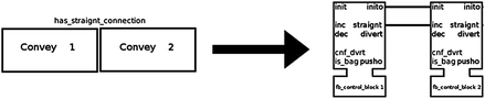
Sequential conveyor connection and its IEC61499 equivalent
-
Rule_3: For each fb_control_block instance which is associated with another FB of the same type, an FB instance of photo_eye type is created as shown in Fig. 6.
Fig. 6. 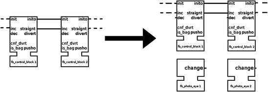
Creating fb_photo_eye between 2 fb_control_block instance


The principal part of transforming the BHS layout to the IEC61499 FB control system is performed in SWI Prolog. The process of then converting Prolog fact database [20] to the target FB ontology is achieved with the OWL Thea 2 library. The graphical representation of the resulting OWL ontology in Protégé is represented in Fig. 7. The yellow box shows the classes of the ontology and the purple boxes are the instances of fb_control_block class and the blue boxes are the object properties.


Resultant IEC61499 ontology in Protégé.
The resulting ontological description of the corresponding IEC61499 FB control system is represented in Fig. 8. This FB system is an IEC61499 application intended to control the BHS from Fig. 3. The final phase in the implementation of BHS control system would be to allocate the generated control application to the resources and devices [8].


IEC61499 application to control BHS from Fig. 3.
6 Conclusion and Future Work
This paper presents a method to automate the generation of control software for cyber-physical systems by transforming ontologies. This is enabled by the Prolog language and results in an IEC61499 application. The presented method follows the framework of ontology-driven engineering (ODE) and can be further extended to including refactoring, generation of formal models for analysis, implementation using programming or modelling languages. The method is applied to a BHS case study where a small fragment of the airport BHS is used as the source model and the resultant IEC61499 control system is transformed. The suggested method is not limited to IEC61499 applications and can be used in other application domains. The method presented in this paper transform the ontology directly on the A-box level of the ontology and the T-Box is unused for this work. In addition, further development of a formal semantics of the language eSWRL is necessary. Moreover, it is important to verify eSWRL transformations.
References
Beydeda, S., Book, M., Gruhn, V.: Model-Driven Software Development. Springer, Heidelberg (2005)
Ledeczi, A., Bakay, A., Maroti, M., Volgyesi, P., Nordstrom, G., Sprinkle, J., et al.: Composing domain-specific design environments. Computer 34(11), 44–51 (2001)
W3C: Ontology Driven Architectures and Potential Uses of the Semantic Web in Systems and Software Engineering (2006)
Grau, B.C., Horrocks, I., Motik, B., Parsia, B., Patel-Schneider, P., Sattler, U.: OWL 2: the next step for OWL. Web Semant. 6(4), 309–322 (2008)
Dubinin, V., Vyatkin, V., Yang, C.-W., Pang, C.: Automatic generation of automation applications based on ontology transformations. In: 2014 IEEE Emerging Technology and Factory Automation (ETFA), pp. 1–4 (2014)
Clocksin, W.F., Mellish, C.S.: Programming in Prolog. Springer, Heidelberg (2003)
Vyatkin, V.: Software engineering in industrial automation: state-of-the-art review. IEEE Trans. Industr. Inf. 9(3), 1234–1249 (2013)
International Electrotechnical Commission: IEC 61499 Function Blocks, vol. IEC 61499, ed. (2005)
Zhabelova, G., Yang, C.-W., Patil, S., Pang, C., Yan, J., Shalyto, A., et al.: Cyber-physical components for heterogeneous modelling, validation and implementation of smart grid intelligence. In: 12th IEEE International Conference on Industrial Informatics (INDIN 2014), pp. 411–417 (2014)
Dubinin, V., Vyatkin, V., Hanisch, H.M.: Modelling and verification of IEC 61499 applications using prolog. In: IEEE Conference on Emerging Technologies and Factory Automation, ETFA 2006, pp. 774–781 (2006)
Dubinin, V., Vyatkin, V.: Graph transformation-based approach to the synthesis of formal models of IEC 61499 function blocks systems. In: Proceedings of the Institutes of Higher Education, Volga Region, Technical Sciences (2008)
Dai, W., Dubinin, V., Vyatkin, V.: Automatically generated layered ontological models for semantic analysis of component-based control systems. IEEE Trans. Industr. Inf. 9(4), 2124–2136 (2013)
Dai, W., Dubinin, V.N., Vyatkin, V.: Migration from PLC to IEC 61499 using semantic web technologies. IEEE Trans. Syst. Man Cybern. 44(3), 277–291 (2013)
Almendros-Jiménez, J., Iribarne, L.: ODM-based UML model transformations using prolog. In: Abelló, A., Bellatreche, L., Benatallah, B., (eds.) Model-Driven Engineering, Logic and Optimization: Friends or Foes? (2011)
Thea: A Prolog library for OWL2. http://www.semanticweb.gr/thea/index.html
Black, G., Vyatkin, V.: Intelligent component-based automation of baggage handling systems with IEC 61499. IEEE Trans. Autom. Sci. Eng. 7(2), 337–351 (2010)
Yan, J., Vyatkin, V.V.: Distributed execution and cyber-physical design of Baggage Handling automation with IEC 61499. In: 9th IEEE International Conference on Industrial Informatics (INDIN 2011), pp. 573–578 (2011)
Protégé. http://protege.stanford.edu
Grosof, B.N., Horrocks, I., Volz, R., Decker, S.: Description logic programs: combining logic programs with description logic. Presented at the Proceedings of the 12th International Conference on World Wide Web, Budapest, Hungary (2003)
Author information
Authors and Affiliations
Corresponding author
Editor information
Editors and Affiliations
Rights and permissions
Copyright information
© 2016 IFIP International Federation for Information Processing
About this paper
Cite this paper
Yang, CW., Vyatkin, V., Dubinin, V. (2016). Automatic Generation of Cyber-Physical Software Applications Based on Physical to Cyber Transformation Using Ontologies. In: Camarinha-Matos, L.M., Falcão, A.J., Vafaei, N., Najdi, S. (eds) Technological Innovation for Cyber-Physical Systems. DoCEIS 2016. IFIP Advances in Information and Communication Technology, vol 470. Springer, Cham. https://doi.org/10.1007/978-3-319-31165-4_4
Download citation
DOI: https://doi.org/10.1007/978-3-319-31165-4_4
Publisher Name: Springer, Cham
Print ISBN: 978-3-319-31164-7
Online ISBN: 978-3-319-31165-4
eBook Packages: Computer ScienceComputer Science (R0)