
Abstract
This paper focuses on the designing procedure of an adjustable anti-roll bar (ARB) for a Formula Student Car. ARB is a component in suspension assembly which can provide a specific understeering effect to the vehicle depending on its roll stiffness. Different drivers prefer different understeering effects on the car depending on their driving style. For this project, Adjustability in ARB leads to 4 roll rate distribution and 3 roll gradients in the car hence overall 12 settings from one ARB assembly. The ARB has been designed using software like MATLAB and MS Excel to obtain the geometric dimensions and specific orientation of the ARB blade pertaining to different balance and stability. This paper also demonstrates the effect of ARB on suspension travel. The proposed method can help drivers to choose the vehicle dynamics according to their driving style in different tracks.
Access this chapter
Tax calculation will be finalised at checkout
Purchases are for personal use only
References
Bhanage, A., PAdmanabhan, K.: Static and fatigue simulation of automotive anti roll bar before DBTT. 10(71) (2015). ISSN 0973-4562
Reimpell, J., Stoll, H., Betzler, J.W.: The Automotive Chassis: Engineering Principles, 2nd edn. ISBN 0 7680 06570
Tuysuz, C., Pasaoglu, A., Durus, M., Ceyhan, A., Tutuk, E., Ozkardesler, B.C., Hatik Ford Otosan, G.: DOE study on ARB to understand contribution of disturbances and FEA correlation (2014)
Tripathi, S., Tiwary, A., Rai, S.: Design of a formula sae chassis according to lateral load transfer distribution. Int. J. Res. Eng. Technol. 06(07) (2017). eISSN: 2319-1163 | pISSN: 2321-7308
Bortoluzzi, L.I., Schommer, A., Martins, M., Buenos, A.A.: Formula SAE chassis design to improve suspension tuning. SAE Paper No. 2016-36-0239 (2016). ISSN 0148-7191
Schommer, A., Soliman, P., Farias, L.T., Martins, M.: Analysis of a formula SAE vehicle suspension: chassis tuning. Society of Automotive Engineers. SAE Paper No. 2015-36-0275 (2015). ISSN 0148-7191
Milliken, W., Milliken, D.: Race car vehicle dynamics. Society of Automotive Engineers (1995). ISBN 978-1-56091-526-3
de Oliveira Santos, R.: A discussion on steady-state lateral weight transfer and how to use it in setup. https://racingcardynamics.com/weight-transfer/ (2015)
Kaplan, H., Hirsch, A.: Gyroscopic motion: show me the forces! Phys. Teacher 52 (2014). https://doi.org/10.1119/1.4849150
Samal, A.K., Eswara Rao, T.: Analysis of stress and deflection of cantilever beam and its validation using ANSYS. 6(1), (Part-4), 119–126 (2016). ISSN: 2248-9622
Author information
Authors and Affiliations
Editor information
Editors and Affiliations
Appendices
Appendix 1: Weight Transfer Equations
-
1.
Gyroscopic Load transfer
Gyroscopic Moment = \(2 \times \left( {lx~ \times ~wy~ \times ~wz} \right)/1.35~\)
Gyroscopic Load transfer = \(\left( {2 \times \left( {l~x~ \times wy~ \times ~wz} \right)/1.35} \right)/Tf\,{=}\,\boldsymbol{6.88}\, {\textbf{pounds}}\)
where, \( wy = \sqrt {\frac{{AyRc}}{R}\quad wz = \sqrt {\frac{{Ay}}{{Rc}}} } \)
- R:
-
Radius of wheel = 0.228 m.
- Rc:
-
Radius of track curvature = 3 m.
- Ix:
-
Area MOI of wheel = 0.278 kg m2.
- wy:
-
Angular velocity of wheel about lateral y-axis = 29.13 rad/s.
- wz:
-
Yawing velocity of wheel about vertical z-axis = 2.214 rad/s.
Note: Gyroscopic Load transfer is positive for outer wheel and negative for inner wheel.
-
2.
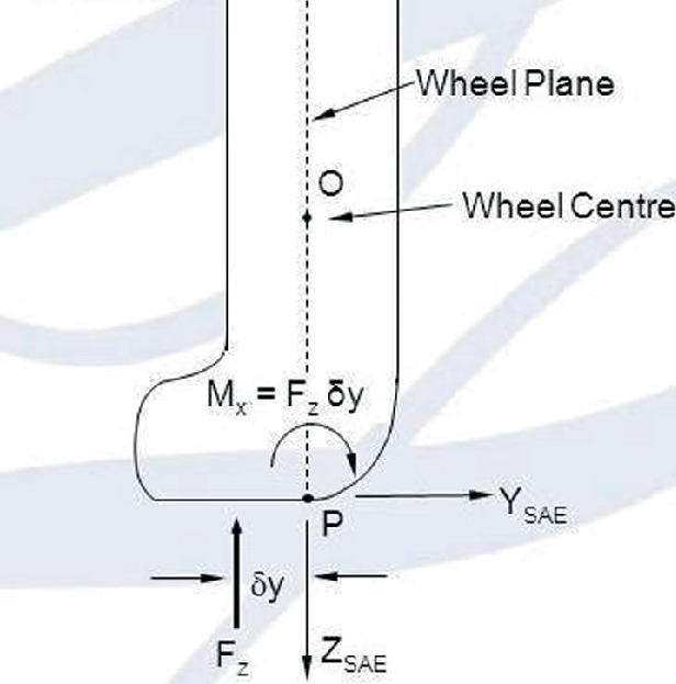
Load Transfer Due To Overturning Moment
The equivalency has been drawn overturning moment at wheel center patch and a force has been assumed at wheel center on its behalf, which is formulated as:\( Ff = \frac{{Mxf}}{R} \)
$$ Fr = \frac{{Mxr}}{R} $$where,
- Mx:
-
= Overturning Moment.
-
The weight transfer due to F has been taken into similar fashion as for un-sprung mass.

Total Load Transfer = Sprung mass Load transfer + Unsprung Mass Load Transfer + Direct load transfer of Front and Rear + Gyroscopic Load transfer + Load transfer due to overturning moment.
W = Weight of Car | b = Distance of CG from rear axle |
Wfu = Front Un-sprung mass | L = wheelbase |
Ay = Cornering Acceleration | Hs = sprung cg height |
Ws = total sprung weight | Tf = Front Track |
WRU = Rear un-sprung Mass | Zub = Height of Rear un-sprung mass |
r = Roll Rate Distribution | Wsb= Sprung mass rear |
Tr= Rear Track | a = distance of CG from front axle |
Wsa= Sprung Mass Front | Kϕ= Roll rate |
Zrf = Height Of front roll centre | Zrr = Height of Rear roll centre |
Zua = Height of front unsprung mass |
Here,
For the start, spring of 26 N/mm was used for both front and rear respectively.
Where, Aero load on the car = 78.6 lbs = Whaero.
Appendix 2: MATLAB Code to Determine the Geometric Dimensions of ARB
%Input force at droop link from Table 38.5
Fwc = 96.542; | % Force at Wheel Centre, N |
%Blade angle adjustment to get the desired deflection from ARB
a = pi/62.3; | % Angle in radian for left blade |
b = pi/62.3; | % Angle in radian for right blade |
%User defined parameters, they can be tweaked to get the desired deflection for a given input % force

%Calculating the deflection at ARB droop link due to right ARB blade

%Calculating the deflection at ARB droop link due to left ARB blade

%Calculating the deflection at ARB droop link due to twist of ARB tube

%Total deflection of ARB droop link due to individual deflection of 2 blades and 1 hollow tube
Twc = ( ( Travel(1) + Travel(2) + Travel(3))/MRarb) |
Rights and permissions
Copyright information
© 2022 The Author(s), under exclusive license to Springer Nature Switzerland AG
About this paper

Cite this paper
Singh, A.K., Prasad, E., Jain, P.K. (2022). Designing of an Anti Roll Bar to Adjust the Balance and Stability of a Formula Student Car. In: Pratap Singh, R., Tyagi, D.M., Panchal, D., Davim, J.P. (eds) Proceedings of the International Conference on Industrial and Manufacturing Systems (CIMS-2020). Lecture Notes on Multidisciplinary Industrial Engineering. Springer, Cham. https://doi.org/10.1007/978-3-030-73495-4_38
Download citation
DOI: https://doi.org/10.1007/978-3-030-73495-4_38
Published:
Publisher Name: Springer, Cham
Print ISBN: 978-3-030-73494-7
Online ISBN: 978-3-030-73495-4
eBook Packages: EngineeringEngineering (R0)