
Abstract
Years before microcontrollers and digital computers were introduced, control system operations, industrial computations, and even simulation of dynamical systems were made possible by use of analog computers. The heart of an industrial analog computer is a device called operational amplifier or “opamp.” These amplifiers consist many transistors to accomplish a theoretical infinite gain to either inputs.
Access this chapter
Tax calculation will be finalised at checkout
Purchases are for personal use only
Author information
Authors and Affiliations
Problems
Problems
-
10.1.
Design an inverting amplifier to obtain gain 100. What is the output voltage if the input is v in(t) = 0.2 sin t V. Discuss the choices you made for the input and feedback impedance.
-
10.2.
An inverting amplifier has the gain of 500. Calculate and sketch the output voltage when the input is 0.2 V at 1 kHz.
-
10.3.
An inverting amplifier has the gain of 500 and the source voltage of ±15 V. Calculate and sketch the output voltage when the input is 0.2 V at 1 kHz.
-
10.4.
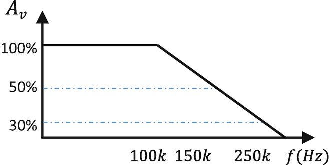
The frequency response of an inverting amplifier with gain 50 is shown. Find the output voltage at the given frequencies.
-
(a)
v in = 5 at f = 1 kHz
-
(b)
v in = 5 at f = 5 kHz
-
(c)
v in = 5 at f = 10 kHz
-
(d)
v in = 5 at f = 15 kHz
-
(e)
v in = 5 at f = 100 kHz
-
(a)
-
10.5.
The frequency of a 100 mV signal to be amplified is 40 kHz. Find the slew rate required from an operational amplifier.
-
10.6.
Slew rate of an operational amplifier is 2 V/ms. Is it suitable for the following cases:
-
(a)
10 V, 5 Hz
-
(b)
10 V, 10 Hz
-
(c)
10 V, 50 Hz
-
(d)
10 V, 500 Hz
-
(a)
-
10.7.
Find the slew rate required for each of the following signals.
-
(a)
1 V, 500 Hz
-
(b)
1 V, 1 kHz
-
(c)
1 V, 100 kHz
-
(d)
1 V, 10 MHz
-
(e)
5 V, 500 Hz
-
(f)
5 V, 10 kHz
-
(g)
5 V, 100 kHz
-
(h)
5 V, 10 MHz
-
(i)
15 V, 500 Hz
-
(j)
15 V, 1 kHz
-
(k)
15 V, 100 kHz
-
(l)
15 V, 10 MHz
-
(a)
-
10.8.
Design a noninverting amplifier at gain of 51. What is the output voltage if the input is v in(t) = 0.2 sin t V.
-
10.9.
Design a noninverting amplifier at gain of 1001. What is the output voltage if the input is v in(t) = 0.2 sin t V.

Add, Subtract
-
10.10.
Design a circuit to perform the following operations, x 1, x 2, x 3, inputs; y, output.
-
(a)
y = x 1 + 10x 2
-
(b)
y = x 1 + 5x 2 − 6x 3
-
(c)
y = 10(x 1 + x 2 − x 3)
-
(d)
y = − 10(x 1 + x 2 − x 3)
-
(a)
Differentiators
-
10.11.
Design a differentiator circuit using inductors to have gain of 30. What is the output of the amplifier if the input is v in = 0.5 sin 500t.
-
10.12.
Design a differentiator circuit using a capacitor to have gain of 100. What is the output of the amplifier if the input is v in = 0.05 sin 500t.
-
10.13.
Using opamps build the following signals, wherein x, x 1, x 2, input; y, output.
-
(a)
\( y=20\frac{dx}{dt} \)
-
(b)
\( y=-0.1\frac{d{x}_1}{dt}+\frac{d{x}_2}{dt} \)
-
(c)
\( y=150\frac{d^2x}{d{t}^2} \)
-
(a)
Integrators
-
10.14.
Design an integrator circuit using inductors to have gain of 30. What is the output of the amplifier if the input is v in = 0.5 sin 500t.
-
10.15.
Design an integrator circuit using a capacitor to have gain of 100. What is the output of the amplifier if the input is v in = 0.05 sin 500t.
-
10.16.
Using opamps build the following signals, wherein x, x 1, x 2, input; y, output.
-
(a)
y = 12 ∫ xdt
-
(b)
y = 50 ∫ x 1 dt + 0.1 ∫ x 2 dt
-
(c)
y = 800 ∫ ∫ xdt
-
(a)
Build Analog Computers
-
10.17.
Build an operational amplifier circuit to implement the following systems (x, input; y, output)
-
(a)
PID controller that takes error as e = x − y. A proportional, integral, and differential of the error is needed.
-
(b)
\( \dot{y}+3y=x \)
-
(c)
\( \ddot{y}+\dot{y}+3y=x \)
-
(d)
\( \ddot{y}+5\dot{y}+6y=\int xdt \)
-
(e)
\( \ddot{y}+11\dot{y}+30y=\dot{x}+5x \)
-
(f)
\( \ddot{y}+11\dot{y}+30y=\ddot{x}+\dot{x}+x \)
-
(a)
-
10.18.
Design an 8-bit digital to analog converter.
-
10.19.
Find the output voltage in the following circuit.
-
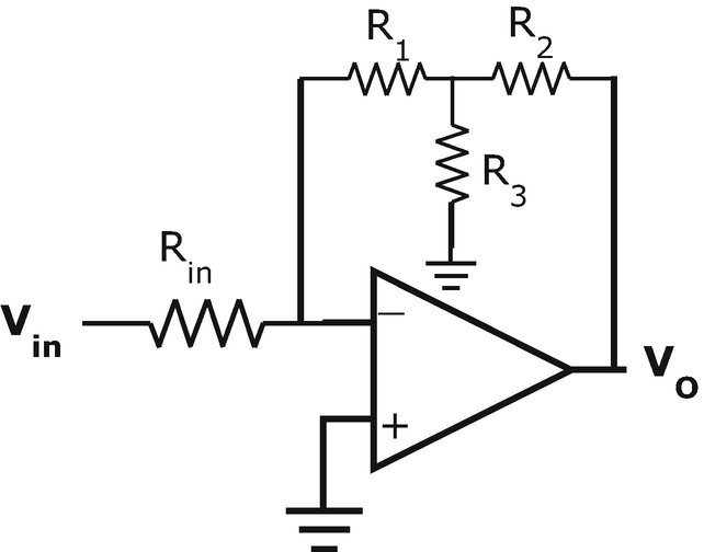
10.20.
Find the output voltage in the following circuit.
-
10.21.
Find the output voltage in the following circuit.
-
10.22.
Find the output voltage in the following circuit.


Rights and permissions
Copyright information
© 2019 Springer Nature Switzerland AG
About this chapter

Cite this chapter
Izadian, A. (2019). Operational Amplifiers. In: Fundamentals of Modern Electric Circuit Analysis and Filter Synthesis. Springer, Cham. https://doi.org/10.1007/978-3-030-02484-0_10
Download citation
DOI: https://doi.org/10.1007/978-3-030-02484-0_10
Published:
Publisher Name: Springer, Cham
Print ISBN: 978-3-030-02483-3
Online ISBN: 978-3-030-02484-0
eBook Packages: EngineeringEngineering (R0)