A Review on Design of Upper Limb Exoskeletons


1
Department of Mechanical and Manufacturing Engineering, Aalborg University, 9220 Aalborg, Denmark
2
Department of Electronics Systems, Aalborg University, 9220 Aalborg, Denmark
*
Author to whom correspondence should be addressed.
Robotics 2020, 9(1), 16; https://doi.org/10.3390/robotics9010016
Submission received: 4 February 2020
/
Revised: 11 March 2020
/
Accepted: 13 March 2020
/
Published: 17 March 2020
Abstract
:Exoskeleton robotics has ushered in a new era of modern neuromuscular rehabilitation engineering and assistive technology research. The technology promises to improve the upper-limb functionalities required for performing activities of daily living. The exoskeleton technology is evolving quickly but still needs interdisciplinary research to solve technical challenges, e.g., kinematic compatibility and development of effective human–robot interaction. In this paper, the recent development in upper-limb exoskeletons is reviewed. The key challenges involved in the development of assistive exoskeletons are highlighted by comparing available solutions. This paper provides a general classification, comparisons, and overview of the mechatronic designs of upper-limb exoskeletons. In addition, a brief overview of the control modalities for upper-limb exoskeletons is also presented in this paper. A discussion on the future directions of research is included.
1. Introduction
Upper limb exoskeletons are electromechanical systems which are designed to interact with the user for the purpose of power amplification, assistance, or substitution of motor function [1]. These devices are usually anthropomorphic in nature, as they mechanically interact with the human upper-limb musculoskeletal structure. They share broad areas of application, e.g., power amplification in an industrial environment [2], neuromuscular impairment compensation [3,4] or post-stroke rehabilitation [5,6], and support for disabled people in their activities of daily living (ADL) [7].
The early idea of exoskeleton was dated back to the late 19th century, but the first successful prototype, called Hardiman, appeared in the 1960s [8]. Hardiman was initially developed for military purposes to enhance the strength and performance of the wearer. It was operated in a master–slave configuration with several hydraulic actuators. In this configuration, two overlapping exoskeletons were implemented. The inner exoskeleton was supposed to follow the human motion that can be eventually used to drive the hydraulic actuators of outer exoskeleton. The device remained at the prototype level due to its relatively high weight and complexity. Afterward, an upper-limb exoskeleton with an idea of physical human–robot interaction (pHRI) was presented by Kazerooni et al. [9]. pHRI permits a direct transfer of mechanical power without using any master–slave system. In the meantime, University of Tsukuba started working on the development of hybrid assistive limb (HAL) and that was commercialized later [10]. HAL was initially developed to support disabled people in ADL, but later versions were also developed for industrial applications.
In the last two decades, the upper-limb exoskeletons used for services and rehabilitation have attracted a lot of attention from the biomedical and engineering sectors. The technology is becoming important as a potential solution for physically weak or disabled people [11]. Systems have been developed to improve the performance and strength of the wearer, e.g., Ekos Vest [2] and FORTIS [12].
Giving high utility and growing demand for upper-limb exoskeletons, the technology is still challenging in the area of mechanism designs, controls, and human–robot interaction. Mechanical design and kinematic analysis are the most crucial issues in developing an ergonomic exoskeleton system. A number of research articles have reviewed upper-limb exoskeletons, particularly for services and medical applications. In addition, performance and effect of these systems are issues being studied extensively. The development in hardware systems of active upper-limb exoskeleton robots was presented in Reference [13] by considering the pHRI [14,15].
A study on the development of upper-limb hybrid exoskeletons in combination with the functional electrical stimulation (FES) was reported by Stewart et al. [16], which mainly focused on post-stroke rehabilitation and patient monitoring. Islam et al. [11] made a review to identify the technological gap between the commercially available robotic exoskeletons and research prototypes used for post-stroke rehabilitation. However, given the extensive studies on the upper-limb exoskeletons, very few articles have reported the exoskeleton’s design addressing complex anatomical movements at the shoulder and wrist joints of the arm and hand as a whole (general hand opening and closing).
It is well understood that exoskeleton robots are highly nonlinear mechatronic systems, and different engineering methods have been used to improve the physical human–robot interaction (pHRI). The interaction between human and the robotic exoskeletons is affected fundamentally by the following: 1. Mechanisms are designed by considering sophisticated biological features and activities for improved pHRI. 2. Mode of actuation and transmission need to be selected in a systematic way by taking in account the compliance/stiffness factor. 3. The selection of the control method also influences the pHRI. Up to this day, review articles are rarely dedicated to the state-of-the-art researches with these three issues. Thus, to review the performance correlation between the aforementioned three elements for exoskeleton applications and the way they contribute toward improved physical human–robot interaction is the main contribution of this article. For this purpose, a comprehensive review on upper-body exoskeletons is presented. Moreover, the article analyzes the key challenges involved in commercialization of research prototypes and compares them with the available market solutions, upon which some new research problems in mechanical design, actuation, and control strategy along with possible direction for future development are identified. The paper discusses first the human upper-limb anatomy and design difficulties involved in the development of an exoskeleton robot. Afterwards, the mechanical design of upper-limb exoskeletons is presented, which is followed by the control strategies, actuation and power transmission, and exoskeleton design modeling. In the end, possible challenges and future aspects on the upper-limb exoskeleton robots are described with conclusion.
2. Upper Limb Anatomy and Design Challenges
The purpose of an exoskeleton is to replicate the kinematics and dynamics of human musculoskeletal structure and to thus support the limb’s motion, which is challenging with the existing mechanisms and mode of actuation. Due to the complex anatomical structure, there is not a unanimous kinematic model available for the human upper limb in the biomechanics literature [17] that could help us to design exoskeletons. Moreover, the exoskeleton’s design parameters heavily depend upon the targeted application. Thus, it is required to analyze the human upper-limb anatomy to design the exoskeleton by considering the end user application.
The human upper limb consists of complex skeletal structure, as shown in Figure 1A which includes shoulder complex, elbow complex, wrist joint, and fingers. The shoulder consists of four articulations (called glenohumeral articulation, acromioclavicular, sternoclavicular, and scapulothoracic) formed between three bones including clavicle (or collarbone), scapula (or shoulder blade), and humerus (or upper-arm bone) [18]. The glenohumeral joint is commonly referred as a ball socket joint, formed between the articulation of humeral head and glenoid cavity [19]. Most of the studies have only considered the glenohumeral joint to model a three degrees of freedom (DOF) shoulder mechanism [20]. However, the glenohumeral joint has an instantaneous center of rotation (COR) that changes with the movement of human upper limbs. Thus, it is highly required to accommodate the effect of the dynamic center of rotation while modeling exoskeleton shoulder mechanism. For this purpose, several approaches have been reviewed in Reference [21] to model the shoulder joint. The primary movements for the shoulder complex are shoulder abduction/adduction, internal/external rotation, and shoulder flexion/extension.
The elbow joint is a synovial compound joint consisting of humeroradial joint and humeroulnar joint [22] shown in Figure 1B. The humeroradial joint is also referred to as a ball socket joint formed between humerus (in the upper arm) and the radial in the forearm. However, its close resemblance with the humeroulnar joint and the proximal radiaulnar articulation constrains the joint movements from 3-DOF to 2-DOF [23]. In general, the elbow joint allows forearm extension/flexion and supination/pronation. Most of the exoskeletons found in the literature have modeled the elbow joint only for 1-DOF flexion/extension.
A wrist is a joint to connect the forearm with the hand. It is comprised of eight carpal bones with several soft tissues to reinforce the joint, shown in Figure 1B. The wrist joint possesses two degrees of freedom movements, which are wrist flexion/extension and radial/ulnar deviation [24]. Wrist motions are generated about an instantaneous center of rotation [25]. However, the range of motion for the instantaneous center is too small and can be ignored, and the rotation axes for the flexion/extension and ulnar/radial deviation are assumed to be coincident [13]. Several exoskeletons have been developed to support the wrist joint based on the assumption that the wrist movement is generated about a fixed center of rotation.
3. Upper Limb Exoskeletons
Upper limb exoskeletons are designed to operate in parallel with the human upper limb and are attached to the human arm at multiple locations. This requires a robot to adapt to different arm lengths. Figure 2 shows a general classification of upper-limb exoskeletons depending on degree of freedom, type of actuation, supporting joints, and applications. However, the authors have classified the exoskeletons into two main categories such as exoskeletons for motion amplification and exoskeletons for medical rehabilitation. Furthermore, the commercially available exoskeletons and the research prototypes are compared and discussed by highlighting the key challenges involved in the mechanical design, control algorithm, and pHRI modeling.
In this article, 69 different types of systems have been reviewed as shown in Table 1, Table 2 and Table 3. Of them, the latest development in the upper-limb exoskeleton technology that have considered the advanced biomechanics of human upper limb in the design phase are discussed in detail while a comprehensive review of other systems can be found in References [13,26,27,28,29].
3.1. Exoskeletons for Motion Assistance
This category of exoskeletons is designed to assist the user in motion amplification or augmentation, where it can be used to assist the users for motion amplification [7,30,31,32,33,34,35,36,37]; helps to reduce the burden while working in a harsh industrial environment [38,39]; or supplements the physically weak individuals in their activities of daily living. So far, many new systems have been developed and tested during past few years. However, only a few systems with limited range of motion amplification applications have been successfully commercialized while others remain as research prototypes.
The following section describes the latest development in the exoskeleton design technology.
3.1.1. EksoVest
Ekso-BIONICS presented a design of a passive upper-body exoskeleton called EksoVest. Two different mechanisms (namely moment generation and hinge mechanisms) are used in the EkosVest that reduce the load and fatigue level of the operator working on the shop floor as shown in Figure 4C. The exoskeleton partially supports the load carried by the user, especially for overhead tasks. Kim et al. [2] has evaluated the performance of EksoVest by simulating an overhead work environment. It has been observed that the vest reduces the shoulder abduction ROM by 10% and increased the center of pressure velocity in the anteroposterior direction by 12% [2]. Moreover, it has significantly reduced the spine loading specifically during the overhead drilling activity.
3.1.2. AAU Upper Body Exo
Bai et al. [40] presented a four-DOF upper-limb exoskeleton with a novel shoulder mechanism for assistive applications. The unobtrusive feature of this exoskeleton is the double parallelogram (DPL) spherical mechanism, which was designed to support 3-DOF shoulder GH movements. This DPL mechanism consists of two revolute joints connected via a passive DPL mechanism (as shown in Figure 3D) to achieve the workspace of a spherical joint with a remote center of rotation. However, singularity-free large workspaces, lightweightness, compactness, and achieving high stiffness values were the special design considerations for the mechanism development. Hence, a simple human biomechanical model was used in Reference [7] to describe the ROM for human shoulder movements to analyze the kinematics, singularities, and manipulability for the DPL mechanism in detail. Dimensional analysis was also conducted to find the design parameters with the maximum range of motion. Moreover, an admittance control was implemented for control shoulder and elbow joints.
The exoskeleton structure with the DPL mechanism can actively support the shoulder extension/flexion and shoulder abduction/adduction, whereas the shoulder rotation was kept passive, which limits its use for several applications.
3.1.3. Five-DOF Wearable Upper-Limb Exoskeleton
Sui et al. [32] presented a 5-DOF exoskeleton, aimed to provide assistance in ADL. The exoskeleton supports five degrees of freedom movements for the upper-limb torso, where three degrees of freedom and two degrees of freedom are given to the shoulder and elbow, respectively. It allows the wearer to maintain a wide range of motion. To solve the power-to-weight limitations of exoskeleton movement, a gravity balance method was introduced to reduce energy consumption. A novel cable-driven mechanism has been used that helps to reduce the total weight to 4.2 kg.
To quantify the reliability of this wearable device, the trajectory tracking performance and the motion assistance level were evaluated. The motion assistance level was evaluated using the surface electromyography (sEMG) sensor band. However, the reliability of this system using sEMG in self drinking, self-feeding tasks, and other ADLs needs to be proved.
3.1.4. CAREX-7
Cui et al. [36] proposed a 7-DOF cable-driven arm exoskeleton that can support the user in providing dexterous manipulation, including translation and rotation. Four custom design orthotic cuffs are used to attach CAREX-7 on the user’s upper limb, as shown in Figure 3H. Based on the “assist-as-needed” paradigm, a novel wrench-field controller is designed to regulate a force or torque on the hand for assisting its dexterous manipulation. CAREX-7 is a cable-driven upper-limb exoskeleton where the actuators are used to remotely control the arm movements and helps to achieve a light weight and low inertia design properties. CAREX-7 makes use of the human skeletal structure as the underlying mechanical system, and lightweight cables are used to actuate cuffs attached to the human upper limbs. The cable-driven architecture can accommodate possible joint misalignment between the human upper limb and exoskeleton and reduces the chances of injuries to the human subject during robot-aided rehabilitation [36]. CAREX-7 is still in the phase of its design improvement, where an adaptive orthosis is required for improved pHRI, which helps to reduce the relative motion between the human arm and exoskeleton. Beside, a self-identification algorithm is required to improve the exoskeleton model, which is expected to be considered in the later studies as reported in Reference [36].
3.1.5. 6-REXOS
Gunasekara et al. [37] proposed a 6-DOF upper-limb exoskeleton (called 6-REXOS) for supporting users with weak neuromuscular impairment. 6-REXOS is equipped with three motion generation units to supplement forearm and wrist movements with four active rotational DOFs and two passive translational movements. Two flexible couplings are attached to the elbow and wrist joint to support the translational movements that help to enhance the kinematic redundancy and to preserve the axes alignment between both joints. The significance of the kinematic redundancy has been evaluated based upon several parameters including manipulability index, singularity analysis, and condition number. Moreover, a kinematic model of a human arm was developed to analyze the mutual compatibility of both systems.
It has been noted that the introduction of the kinematic redundancy improves the maximum and minimum manipulability index by 21.13% and 22.25%, respectively [37]. Furthermore, it is concluded that adding kinematic redundancy to the 6-REXOS through a flexible coupling improves the manipulation, which guarantees a comfort motion assistance.
3.1.6. Stuttgart Exo-Jacket
Ebrahimi et al. [46] proposed an exoskeleton for motion assistance in industrial applications by considering the ergonomical aspects. Stuttgart Exo-Jacket was specifically designed for the installation of 32 kg of cable in the cable duct of transportation buses. Hence, the exoskeleton was designed to actively support the extension and flexion of the shoulder and elbow joint. Based on these requirements, the human upper-body dynamics was analyzed from the mechanical design perspective. However, it was noted that the micro-misalignment caused by the non-coincident center of rotation between human arm joints and exoskeleton joints is a critical issue. The ill effect of this issue was minimized while directly installing the drives at joint location, as shown in Figure 3G.
Moreover, a mechanical and a gas spring mechanism, mounted on the back of the user, help to bypass the applied forces on the human elbow and shoulder joints. The Stuttgart jacket also has a passive lower-extremity module, which helps to ground the applied forces on the upper-limb module. The technical features of Stuttgart Exo-Jacket was selected based on the ergonomical analysis of the task and environment.
3.1.7. Robo-Mate Exoskeleton
Stadler et al. [60] developed Robo-Mate for the purpose of power amplification in the industrial environment, as shown in Figure 4E, where it was used to assist the user in lifting and transporting different objects over a short distance. The mechanical design of Robo-Mate is modular, which can assist at various levels of activities. It consists of three modules, namely the trunk module, a passive arm, and an active arm. The trunk module was designed to prevent the user’s lower back from excessive compression forces.
The passive arm is a spring-loaded four-bar chain parallelogram structure with a gravity compensation effect. The passive arm has an adjustable mechanism connected with one end of the spring inside the parallelogram structure that helps to adjust the level of assistance required by the user.
Due to the modular design of Robo-Mate, the mode of assistance can also be changed from passive to active depending upon the user requirement, where the spring can be replaced with wire. By adding the cable and by removing the front and upper link of the parallelogram structure, it can transform to a triangular shape mechanism which is serially connected with a rear parallelogram assembly. Moreover, a brushless DC motor EC-i40 with a worm gear assembly is used to drive the cable, mounted at the trunk end of the module. The whole assembly was made from aluminum, and it weighs approximately 2.3 kg excluding battery pack. Safety and risk analyses were also considered in the design procedure, which make this product mature enough and able to be used in the automotive industry [61].
3.1.8. Compliant Robotic Upper-Extremity eXosuit (CRUX)
Lessard et al. [31] proposed a soft exosuit for upper-limb rehabilitation, shown in Figure 3B. The study has identified the drawback of classical rigid body exoskeletons and their inability to comply with natural human body movements in a flexible way [62]. Thus, it is highly required to design a flexible and compliant exoskeleton that can conform to the nonlinear musculoskeletal structure. Based on these requirements, a tensegrity design of upper-limb exoskeleton was proposed and a cable-driven mechanism was used to transmit the power mechanically. These cables were routed on the base layer of the exoskeleton and used to directly supplement the human arm with 6 micro motors mounted on the backplate. The routing path of cables was carefully chosen so that they can supplement the influential muscle group of the human upper limb.
Later, the design of CURX was improved by introducing some extra safety features such as motors that were limited to never apply more than 88.3 N forces. A set of inertial measurement units (IMUs) was also used to avoid any harmful configuration achieved by the exoskeleton robot, e.g., any IMU-sensed angle pair with more than 40 degrees in difference would stop the motors. However, there is no comprehensive study measuring the effectiveness of CRUX for the active assistance [42] and the design needs some additional degrees of freedom to adopt actual human biomechanics.
3.1.9. Soft Extra Muscle (SEM) Glove
The SEM glove, developed by BioServo technologies [4], shown in Figure 4J, has provided a viable solution for improving grasping capabilities. The properties of the fabric and textile design were considered for proper functioning of the glove that can efficiently transfer the forces and torques to the fingers. Based on the biomechanical analysis, the closing of a hand was analyzed and a special cable-driven transmission system was designed for the glove-closing mechanism. The cables were routed from the side of the fingers and passed through the distal phalanx. The criteria for cable routing on the glove was carefully considered in such a way that they can maximize the equal distribution of the forces on the fingers. The provided solution was very close to the biological solution in its kinematic and dynamic properties, but the glove is not able to support opening of the palm. Moreover, three tactile sensors and force sensors are inserted inside the distal phalanx and palm of the glove, respectively. These sensors provide real-time feedback for controlling human grasp by providing adjustable servoing. The device is successfully commercialized and available in the market. It can only supplement the user in grasping an object but is not capable of supporting the hand opening function, which limits its use for rehabilitation applications.
3.2. Exoskeletons for Medical Rehabilitation
The second type of exoskeleton is used for rehabilitation of physically impaired patients suffering from post-stroke paralysis, amyotrophic lateral sclerosis, or other physical or cognitive impairments. Additionally, these devices are also employed to provide therapy consistently for a longer period, irrespective of the fatigue level and training skill of physiotherapists. For example, Amendo, a 5-DOF robotic exoskeleton [92], ALEx [93], and Dynamic arm support [94] are already developed and commercially available in the market.
The exoskeletons reviewed in this section are either mounted on a mobile/stationary platform and can not be carried by the users independently or can be used only in the clinical settings under appropriate supervision. For these exoskeletons, compliant actuation and selection of an optimal control algorithm are main concerns. Some latest developments in this technology are described in the following section.
3.2.1. Upper-Body Exoskeleton for Rehabilitation (Harmony)
Kim et al. [2] developed an upper-body exoskeleton intending to achieve advanced kinematic and kinetic properties for upper-limb rehabilitation. The robotic exoskeleton consists of five degrees of freedom shoulder mechanism and one degree of freedom elbow and wrist mechanisms actuated by series elastic actuators (SEA). By keeping in view the complex shoulder anatomical movements, a new mechanism was designed by combining a revolute joint and parallelogram mechanism to support the girdle movement. In this mechanism, a revolute joint is used to support the shoulder elevation and depression movement, and the parallelogram mechanism facilitates shoulder protraction and retraction. Moreover, this parallelogram mechanism is then connected to a virtual ball socket joint assembly. This ball socket joint supports the three degrees of freedom upper-arm movements by preserving the center of rotation inside the GH joint.
Another unique feature of the exoskeleton design lies in the development of new forearm supination and pronation mechanism. This mechanism consists of a parallelogram assembly and a transmission that supports forearm supination and pronation. A study conducted in Reference [95] has presented the kinematic compatibility of the shoulder mechanism over a wide ROM. The anatomical compatibility was quantified by measuring the residual forces in the interaction port during the coordinated shoulder movements.
3.2.2. Parallel Actuated Shoulder Exoskeleton
Hsieh et al. [41] has proposed a parallel actuated shoulder mechanism shown in Figure 3A. It consists of two spherical mechanisms, two slider crank mechanisms, and a gravity balancing mechanism. The actuators are designed in a way that they are always kept side-by-side to each other. This method ensures not only superior inertia properties but also compactness and less weight. An adaptive mechanism with a passive joint is introduced to compensate for the exoskeleton-limb misalignment in case of variable physiological parameters of the user. Further, linear series elastic actuators (SEA) have been used to obtain accurate force and impedance control at the exoskeleton-limb interface.
The exoskeleton was designed to be mounted on a stationary platform, which limits its use for several other applications. Beside, the compatibility of the proposed design has to be investigated by considering shoulder GH movements, which can affect the ROM for the human upper limb.
3.2.3. 5-DOF Parallel Actuated Shoulder Exoskeleton
Hunt et al. [67] presents a five degree of freedom parallel actuated shoulder exoskeleton. This shoulder exoskeleton is comprised of a three degrees of freedom spherical parallel mechanism (SPM) and a 2-DOF passive slip interface. The SPM consists of three parallel linear actuators coupled to the shoulder joint using a three-DOF tie-rod joint. Further, the shoulder joint is connected to the human upper arm via a passive slip interface, which can support 1-DOF translational slip and 1-DOF rotational movement. This slip interface increases system mobility and prevents joint misalignment due to the translational motion of the user’s glenohumeral joint from introducing mechanical interference. The parallel architecture presented in the study [67] offers a low-inertia solution, which is vital for the better performance of wearable devices.
3.2.4. NEUROExos
Lenzi et al. [96] proposed a portable robotic elbow exoskeleton named NEUROExos. This exoskeleton was designed for the rehabilitation of a typical type of motor disorder called spasticity. The initial design of NEUROExos was developed with the aim of solving two critical issues. These issues include the localization and distribution of interaction points between the exoskeleton and human arm. The localization issue was resolved by introducing an adaptive mechanism for the elbow joint. This adaptive mechanism consists of two major assemblies, that includes double-shell structured link-based assembly and a 4-DOF adjustable passive mechanism.
A 4-DOF adjustable mechanism was used to preserve the alignment between the human elbow joint axis and robotic exoskeleton, and the double-shell structure assembly was used to fixate the human arm with the exoskeleton structure. NEUROExos was driven by a remotely located Bowden cable-based transmission unit.
In a later version, bio-inspired morphological characteristics were introduced by adding the compliance in the mechanical design using nonlinear elastic elements and custom-made torsional springs [97]. NEUROExos was developed by carefully analyzing the neuro-scientific motion requirement, and later, it was used in several experimental studies to cure neurological disorders [68].
3.2.5. EAsoft Module for Neuro-Rehabilitation
Oguntosin et al. [74] described the design of an active exoskeleton built with the soft modules (EAsoftM). Integrating the 3D-printed exoskeleton with passive joints to compensate gravity and with active joints to rotate the shoulder and elbow joints resulted in an ultra-light system that could assist planar reaching motion by using visual servoing. The EAsoftM can support the reaching motion with compliance realized by the soft materials and pneumatic actuation. In addition, a vision-based control has been proposed for precise control over the target-reaching motion within the millimeter scale.
3.2.6. Cable-Driven Upper-Limb Exoskeleton
Shao et al. [69] presented an optimal design of three degrees of freedom cable-driven upper-arm exoskeleton. To achieve an optimal design challenge, a study was conducted by keeping in mind the major limitation of modeling the cable-driven mechanisms and the way it impact the rehabilitation performance. For this purpose, two promising configurations of the cable-driven upper-arm exoskeleton are proposed upon analysis of the working conditions. Global force indices are defined to evaluate the force applied to the human arm by the exoskeleton to improve the system’s safety and comfort. Optimum design was obtained with projected force indices. However, due to the complex human biomechanics and the limited design options, it is always difficult to define a comprehensive relationship between design parameters and exoskeleton performance.
3.2.7. Upper-Limb Exoskeleton for Rehabilitation
Wu et al. [70] proposed a gravity-balanced exoskeleton for active rehabilitation training of the upper limb. The kinematic structure of the exoskeleton is described and optimized to enable natural mode of interaction with the user and to avoid singular configurations inside the workspace. The gravity balancing of the human arm and mechanism is achieved through a hybrid strategy making use of auxiliary links and zero free-length springs to balance the effect of gravity over the range of motion. The balance errors resulting from the variation of anthropomorphic parameters are also analyzed.
3.2.8. Active Elbow Orthosis
Ripel et al. [73] presented the design of a motor-powered rehabilitation device, called Active Elbow Orthosis (AEO). The device was initially designed for the elbow joint but can be easily modified for other joints as well. AEO determines the motion activity of the user using a strain gauge and utilizes this measurement to control the actuator that drives the forearm part of the orthosis. User activity level is related to a free arm measurement obtained through a calibration procedure prior to the exercise. A control module offers several types of exercises mimicking physiotherapy. The device was verified by tests on a number of patients, resulting in an extended range of elbow-joint movements.
3.2.9. eWrist
Lambelet et al. [79] developed the eWrist, a wearable one degree of freedom powered exoskeleton which supports wrist extension training. This device operates on a principle of assist-as-needed basis, which means that it can only enhance motor activity but cannot replace it. Stroke patients may not have the ability to produce overt movements, but they might still be able to produce weak muscle activation that can be measured via surface electromyography by combining force and surface electromyography-based control in an assist-as-needed support strategy. The purpose of this training device is to enhance the activity of the wrist extensor muscles for ADL, thereby driving cortical reorganization and recovery.
3.2.10. Under-Actuated Hand Exoskeleton
Sarac et al. [78] presented an adaptable under-actuated hand exoskeleton which can support the user in grasping different objects with variable geometric parameters. The grasping tasks are improved by allowing only the normal transmission of the forces on the finger phalanges. The absence of the tangential forces allows the device to be attached to the user’s finger in an easy and comfortable manner for operation. Furthermore, the finger size adjustability can be ensured by the linkage-based design. Under-actuation assures the automatic adjustability of the device for the grasping objects while preventing posture control of the finger phalanges. The disadvantage of the under-actuation approach is suggested to be overcome by utilizing an additional potentiometer on the device in order to estimate orientation of the finger and the pose analysis of the mechanism during operation.
3.2.11. Advanced Service Robot (ASR) Glove
Hadi et al. [80] presented a novel lightweight hand exoskeleton robot, which is called an advanced service robot glove. The glove is operated via a tendon-based shape memory alloy (SMA) mechanism, which can be utilized for both rehabilitation exercises and motion amplification for people with hand disability. To realize the proposed glove, after the conceptual design of the robot, the kinematics and force analysis of the system are elaborated analytically and verified using an experimental prototype of this device. The study shows that the proposed system can flex and extend fingers in their range of motion: angular movements of 80, 90, and 70 can be generated at the distal interphalangeal, metacarpophalangeal, and proximal interphalangeal joints, respectively. Moreover, ASR glove can provide an effective grasping force of 40 N at the distal phalanx of each finger. However, to study the durability of the systems considering the SMAs, the precise control of fingertip force, robot motion speed analysis, and evaluation of the fatigue effect are challenging tasks for this type of glove.
3.2.12. Hand Exoskeleton for Post-Stoke Patients
A 3D-printed hand exoskeleton was proposed for post-stroke rehabilitation by Abdallah et al. [90]. EMG signals were used to estimate the required muscle force for the hand motion, and the designed mechatronic system detects the intention of hand opening or hand closing from the stroke subject. Based on an embedded controller and five servomotors, the low-cost robotic system is able to drive in real time three degrees of freedom for each finger. The experimental tests with-post stroke subjects showed that the designed hand exoskeleton architecture has a positive effect on the motion finger range and mainly in the hand ability to perform some simple tasks.
3.2.13. Spring-Assisted Hand-Opening Exoskeleton Module for Functional Rehabilitation
Butler et al. [83] proposed data-driven design parameters to enhance the functionality and to improve the assistance profile of the ArmAssist-2.0 hand module. Improvements include adjustable linkages for different users, new joint locations to more accurately represent biomechanics of the hand, and a more impairment-appropriate torque profile to assist in hand opening, adjustable through interchangeable springs. It showed that the final assembled device fits comfortably in the hand with noticeable improvements in joint locations, adjustability, and the force profile for the metacarpophalangeal joint. However, there is a challenge with the extension of the proximal interphalangeal joint due to the nature of rapidly changing moment arms and multiple springs in series.
3.2.14. Spring-Assisted Exoskeleton Module for Wrist and Hand Rehabilitation
Perry et al. [84] reported on the development of exoskeleton, which enables training of the fingers and thumb in grasp and release tasks. The design has been made as an add-on module for use with the ArmAssist arm rehabilitation system. Variable-position springs and adjustable link lengths provide adaptability to fit a variety of users. A few structural components were machined from aluminum or steel to produce a functional prototype with sufficient strength for direct evaluation. The design includes independent and adjustable assistance in finger and thumb extension using various width elastic bands and measurement of user grasp/release forces in finger flexion/extension, thumb flexion/extension, and thumb adduction/abduction using low-profile force-sensitive resistors.
Table 1 and Table 2 summarize the upper-limb exoskeleton research prototypes for motion assistance and rehabilitation respectively. Only a few are successfully commercialized and deployed by users, while others are research prototypes and try to address more complex issues. The MIT-MANUS exoskeleton for upper-limb rehabilitation [111] is an example that helps the patient regain motor function. There are also other different modules, namely InMotion robotics, developed. These modules are now available in the market and are being used in more than 20 countries for a neuro-rehabilitation purpose. ALEx [93] developed by the Kinetek wearable robotics is a 6-DOF active exoskeleton used for post-stroke rehabilitation. Table 3 lists available commercial upper-limb exoskeletons.
4. Control Strategies
There are three main robotic-mediated control strategies for assistive devices [28], as shown in Table 4. These are assistance, correction, and resistance [112]. Assistance implies that the robot is supporting the weight of the impaired limb and providing forces to finish the assignment. If the patient is not creating any effort, the task completion can still be accomplished depending on the level of assistance provided by the robot. Correction mode implies the rehabilitation scenario in which the robot acts only when the patient makes wrong movements. It will then force the impaired limb to perform the actual movement which was supposed to be performed by the patient. The resistance control is that the robot restricts the movement. It mostly increases the complexity of the task for the patient to make them learn and improve their capability to correct errors in movement. Assistance helps a patient in the completion of the task, whereas correction does no such thing; rather, it only corrects when something goes wrong. Mostly, the rehabilitation process is not focused on one strategy; instead, it is focused on a combination of these strategies [113]. Most of the existing exoskeleton controllers use a combination of assistive and corrective controllers. Resistive controls can be used in the exoskeletons for tremor suppression for exercises.
4.1. Assistive Mode
There are two types of assistive control modes: passive control mode and partially assistive mode. These modes are also used as a hybrid in some cases. The only difference between the passive and partially assistive modes is the participation of the patient. Therefore, if the patient is not participating, then both these modes will behave similarly without any difference.
4.1.1. Passive Control
A reference trajectory represents a suggested path by which the controlled variable should converge on the set-point in a specified manner. The easiest way to control an exoskeleton is to control its motion rigidly along a certain reference trajectory with the help of the position feedback control. For neuromuscular rehabilitation, this technique is used in the early stages of the process because, at that time, the impaired limb is not responding and the only movement it can do is passive, that is, with the help of the robot. This makes the feedback control system all the more important so that it must be properly calibrated to not hurt the user when an error in its trajectory is made. The reasons for errors can be frequent muscle contraction. As a solution, mechanical checks to avoid errors like elastic straps or serial mechanical fuses can be introduced [114].
a. Passive trajectory tracking This can be achieved with the help of many different techniques. The simplest of these techniques is the use of proportional integral derivative feedback control, which regulates the position of the force along a specified trajectory [115,116]. Diverse techniques exist for characterizing reference trajectories. For passive techniques, these references are regularly made by recording the therapist contributions regarding the subject limb joined to the exoskeleton amid a teaching stage. In this stage, the robot set in a transparent mode (generally accomplished by embracing a feed-forward term to make up for the gravity and the dynamics of the robot) to restrain any protection from performing movements. Once recorded, the exoskeleton is prepared to replay the trajectory with its feedback controller [117].
b. Passive mirroring This category of passive control can be used for the exoskeletons that are intended to support both human arms simultaneously. It involves the synchronous passive mimicking of the movement and behavior of a healthy limb. It is employed in a master and slave configuration [118]. A healthy limb is considered the master, and the exoskeleton is considered the slave; they are synchronized so that the exoskeleton can mimic the behavior of the healthy limb and then later behave like that independently as well [119,120].
4.1.2. Partially Assistive Control
Passive motions for stimulating neuroplasticity are found to be inadequate and limited at best since the user is not participating in performing the task [120]. On the other hand, assistance is required to diminish disappointments towards the start of the treatment, in this way keeping up subject motivation, intensity of the therapy, and trust in utilizing the impaired limb and keeping away negative reinforcement [121]. If the result of the therapy is positive and the patient is going to regain their motor capability, then at that very moment, the control of the movements must be shared between the patient and the robot [122]. There has to be built-in mechanism in the robots that must allow the motor movement of the patient, no matter how little when they are recovering, without suppressing it.
a. Impedance/admittance control Real-time adaptability between the robotic exoskeleton and contact forces is required to improve the interaction between two bodies. To achieve this objective, impedance control is referred to as the most appropriate control technique [123]. Impedance control is a model-based force controller with position feedback. Bai et al. [40] used an impedance control for a 4-DOF upper-limb exoskeleton to improve human–robot interaction that helps to regulate the user manipulation and traction forces.
MIT-Manus [124] employed impedance control to improve robot compliance. This technique is widely used in robotic exoskeletons to improve the pHRI, and it has been observed that this method is quite effective in the case of lightweight (i.e., cable-driven systems) and back drivable systems whereas impedance control may have some technical complexities: the impedance control parameters should not be constantly fixed. Different impedance parameters tend to affect robot compliance. For example, low impedance is less likely to force the user to move beyond their limits while ensuring safer interactions and vice versa. Hence, an adaptive method is required that guarantee the dynamic performance of the exoskeleton robot [125].
Kiguchi et al. [126] proposed an adaptive EMG-based impedance control technique for upper-limb exoskeletons. The proposed method was used to estimate the joint torque based on the EMG signals and is adaptable to variable users. A neuro-fuzzy matrix modifier is used to update the impedance parameters. Similarly, SUEFUL-7 [127] uses the upper-limb posture and EMG activity level to update the impedance parameters in real time. The purpose of adaptability is to estimate joint torques correctly and to then update the impedance parameters accordingly for physical human–robot interaction. For exoskeletons that lack back drivability, admittance control is a better option.
4.2. Corrective Mode
This control method is used when the user is not executing the movement correctly. If the user is not participating, then this technique will no more support the user.
Tunneling
Tunneling comprises making virtual channels for the end-effector or the joints of the exoskeleton in which the subject moves: once he/she leaves the channels, the input control takes them again into the channel as though a spring impedance was connected from the limb to the focal point of the virtual channel. Moreover, to keep the subject from stalling out amid the movement, a supporting force toward the channel is by and large included. Along these lines, burrowing procedures can be viewed as an impedance control with a focused no action zone, i.e., one can consider the supporting power field as an assistive term and the spring damper-like power toward the focal point of the channel as a remedial term.
In Reference [128], a channel was applied on an end-effector position where a force feedback scheme is adopted based on the desired velocity of human upper limb. Gravity torque and friction compensation were also considered in the control input. Further, sub-trajectories have been defined inside the trajectory tracking algorithm and it updates the tunneling direction as the user achieved the subtask. The method has been evaluated on several healthy and disabled people, and the results showed the significance of this control paradigm specifically in providing therapy. The same technique was evaluated clinically on 77 post stroke patients, and function motor score was reported higher as compared to users undergoing conventional therapy [129]. A similar approach was used by Cui et al. [36] to restore the neuromuscular dysfunction.
5. Actuation and Power Transmission
An appropriate torque is required to drive the exoskeleton. There are three primary means to actuate an exoskeleton, electric motors, hydraulic/pneumatic actuators, and linear actuators. The selection of actuators in the exoskeleton design is important because it tends to increase the weight of the structure, but it also depends upon the targeted application. Thus, it is highly required to select an actuator that can have a high power-to-weight ratio and can produce high torque with precise movement.
Electric actuators are mostly adopted due to their straightforward approach to store electrical energy, and they are fairly capable in providing greater controllability using advanced motion control [40,46,130,131]. A few researchers [132] contend that electric actuators are as quite substantial, contrasted with their pneumatic counter part, and that their impedance is too high to be in any way utilized as a part of rehabilitation applications. In any case, a moderately high power-to-weight proportion of pneumatic actuators is accomplished by ignoring the heaviness of the power source. Including a flexible component in the arrangement with the actuator may likewise alleviate the high impedance of electric motors. This idea became a benchmark for the development of Series Elastic Actuators (SEAs) [133]. SEAs reduce inertia and user interface to provide a precise and stable force control, resultantly improving the safety of the subject. However, this principle is not always true as the elastic energy stored in the spring can be suddenly released during an impact or mishandling of the device and can cause unexpected reaction forces [134].
Hydraulic actuators are powered by hydraulic pressure. They can produce greater torque as compared to the electric and pneumatic actuators [11]. The system is relatively complex considering the maintenance of pressurized oil under pressure to prevent leakage. The system also requires more space to accommodate oil pipes and conduits. Commercially available hydraulic systems are also heavy; therefore, only specially designed hydraulic systems are required in rehabilitation robotics. Due to its capability to provide high power, some studies have considered the hydraulic actuator in their work [116,135].
Pneumatic actuators are powered by compressed air. Special compressors or containers with compressed air are required for power. They have lower impedance and weigh less than electric actuators. They are low maintenance and can be stopped under a load without compromising patient safety. Moreover, they are less prone to hazardous and humid environments [136]. A few studies have considered the pneumatic actuators in their systems [114,137]. However, the biggest drawback is their limited precision and accuracy. Due to this reason, the number of exoskeletons that use pneumatic actuation are fairly limited. A pneumatic system requires pneumatic pressure; therefore, exoskeleton robots using pneumatic actuators are mostly stationary platforms, so their service area becomes limited. In some cases, there is a need to install a compressor for the users.
All types of actuators have their own advantages and disadvantages. There are also few systems which use a combination of these systems.
6. Exoskeleton Design Modeling
Robotic exoskeleton and the human limb are two separate dynamic systems. To ensure a safe and compliant interaction between these two systems is a principal challenge. Several engineering solutions have been proposed to improve the interaction between human upper limb and exoskeletons by introducing new mechanisms, modes of actuation, and control techniques [138]. On the other hand, a comprehensive musculoskeletal model is required to study analytically the effect of upper-limb exoskeleton that leads to evaluating and possibly optimizing the robot design.
Attempts have been made to understand and model the human musculoskeletal structure [139]. A few multibody-modeling tools for the purpose of musculoskeletal analysis are also available that include AnyBody Modeling system [140], Virtual Interactive Musculoskeletal system (VIMS) [141], OpenSim [142], and MB Dyn [143]. These tools can be used for the kinematic and dynamic analysis of the human musculoskeletal system and facilities access to the relevant biological data such as reaction forces of the musculoskeletal system [144].
Pay virtue of the modeling software, studies have been conducted to improve pHRI through human musculoskeletal modeling. For example, Zhou et al. [145] proposed a user-centered design optimization technique for robotic exoskeleton via biomechanical simulation. In this study, a human musculoskeletal system was modeled as a multibody system. In the multibody modeling of a musculoskeletal system, the human joints and bones were modeled as mechanical joints and rigid links respectively, whereas the muscles exerted the force on the system. This musculoskeletal model was then used to simulate the arm motion and muscle reaction forces. Furthermore, this model allows to simulate the nonfunctional muscles as well as helps in redefining their functional capabilities. Thus, the response of the human upper limb to the robotic exoskeleton was calculated in terms of muscle activity, and a design approach was evaluated for the robotic exoskeleton. Moreover, the design parameters for the robotic exoskeleton were optimized using a genetic algorithm. This optimization approach demonstrated the effectiveness of robotic exoskeleton for supporting the user in the selected activities that involve slow manipulations.
Troste et al. [146] presented a framework for analyzing the human–robot interaction to optimize the design parameters for upper-limb exoskeleton using musculoskeletal modeling and an analysis tool called Anybody modeling system. This modeling system was used to analyze the level of assistance provided by the exoskeleton to the musculoskeletal model under different loading conditions. Moreover, the Anybody modeling system was used to obtain the dynamic equilibrium equations by considering the applied forces/torques as a measured input. These equilibrium equations were found redundant and were solved as an optimization problem to calculate the muscle and joint forces. Furthermore, the study proposed that the adjustable gravity compensation for upper-limb exoskeleton have a potential to adjust partial muscle activation and internal reaction forces.
Zhang et al. [147] proposed a human–robot interaction modeling approach for hand exoskeleton. In this study, the hill muscle model and hand physiological structure were considered to model the muscle movements. Based on the statical analysis, the interaction between the exoskeleton and hand were studied. Moreover, a physiological cross-sectional area method was used to solve the redundancy problem and eventually leads to calculating the muscle forces and Hill muscle model parameters optimally. The proposed technique can provide the quantifiable muscle parameters that can be further used in the controller design to improve the human–robot interaction.
Shao et al. [69] developed an optimal design of a cable-driven upper-limb exoskeleton by considering the forces exerted on the arm model. The study investigated the optimization of the design parameters by considering the workspace requirement as well as studied the effect of forces acting on the human arm by a robotic exoskeleton. For this purpose, two force indices were defined to analyze the comfortable and safe interaction between the two systems. Firstly, the local arm forces were modeled, which help to analyze the forces exerted on the human upper limb under the action of gravity. Secondly, two global force indices were considered to investigate the performance of robotic exoskeleton in the entire workspace. The study demonstrated that the biomechanical modeling is essential to design an exoskeleton that can support the user without hindering the ROM.
Jensen et al. [148] have presented a passive upper-extremity orthosis that uses a musculoskeletal model to optimize the stiffness of the springs. The solution provides partial support to human upper limbs against gravity for an internally rotated glenohumeral joint.
7. Possible Challenges in Upper-Limb Exoskeleton Development
The exoskeleton technology has proven its significance in different areas of applications, as explained previously. However, there are still many challenges and open research questions that require attention. Some of the general design parameters directly associated with exoskeleton development are mentioned below, whereas the later section will cover more complicated issues with some open research questions.
7.1. Kinematic Compatibility
Exoskeleton design should be kinematically compatible with the variable anthropomorphic parameters of the end-user. The proper alignment between the exoskeleton and the anatomical joints of the wearer is still challenging. Particularly, the exoskeleton mechanism, which supports the shoulder and wrist joint, has to be kinematically a spherical joint [149]. It is required to replicate the actual shoulder and wrist movements that help to overcome the misalignment issues and to ensure the biomechanical compatibility of the design. Castro et al. [44] proposed a 3-DOF scissor mechanism for the shoulder joint. The kinematic analysis of this spherical mechanism and motion capture data validation have been used to verify 3-DOF reachable workspace. The mechanism was tested on the passive exoskeleton, while the integration of the actuator can make it more complex and can limit the workspace. Similarly, a DPL mechanism presented in Reference [7] supports 3-DOF shoulder movements, but the shoulder internal/external rotation was kept passive, which limits the use of this mechanism for other applications, i.e., rehabilitation and therapy. Both mechanisms [7,44] are not able to support shoulder elevation/depression and protraction/retraction. Kim et al. [6] has presented a mechanism to actively support the COR of the glenohumeral joint during the shoulder girdle movements. Further, a quantitative study was carried out to analyze the kinematic compatibility of the shoulder mechanism by measuring the forces in the interaction port during coordinated shoulder movements, which was rarely reported by the other researchers [2]. Hunt et al. [67] has presented a novel five-DOF parallel actuated shoulder exoskeleton, where the principle of three-DOF spherical parallel mechanism was used to actively support glenohumeral shoulder movements. Additionally, a two-DOF passive slip mechanism was introduced to support the user’s upper limb and prevents joint misalignment caused by shoulder protraction and retraction.
On the other hand, several studies [41,84,150] have proposed spherical mechanisms to replicate the 3-DOF shoulder and wrist movements, but most of them have considered the shoulder and wrist joints as a ball socket joint. This consideration is not able to provide optimal solution against designing a mechanism which could accommodate the effect of instantaneous center of rotation for shoulder and wrist joints.
Hand exoskeletons are uniquely qualified to perform a variety of useful functions. Thus, a compact mechanism that could be attached to the human hand and that could move synchronously with the fingers joints is required. However, the main design challenge lies in the development of a thumb mechanism, which is considered as the most complex part, and the kinematic model for its movements are still being defined [151]. Till now, a variety of soft, underactuated, quasi-passive and a combination of passive and active mechanisms have been developed by considering the end-user application. Based on the application, it is common practice to keep some DOFs passive. Given the size of a hand, it seems impractical to develop a mechanism that could actively control the individual joint movements without the overlapping [27].
7.2. Workspace Limitation
Wearable exoskeletons are not able to provide a wide range of motion in comparison to the human upper-limb torso [7]. For example, References [7,44] have presented the new mechanisms to assist three-DOF shoulder glenohumeral movements and to also maintain the instantaneous COR in supporting several ADLs. Since the mechanisms supporting shoulder GH movements only tend to reduce the actual upper-limb workspace but the effect is acceptable in some applications, so far, several studies have tried to address this limited workspace challenge in their design by considering shoulder girdle movements at the cost of complex and heavier mechanism [2,67]. It is observed that the desired envelop and volume of workspace depend upon the target applications. For this purpose, it is mandatory to analyze the mutual ROM for the human arm and exoskeleton to achieve the desired workspace, which can be done by analyzing the kinematic and dynamic model of both systems. However, the wide ROM can only be achieved at the cost of a complex and heavier mechanism.
7.3. Singularity Problem of Mechanical System
It hinders the smooth manipulation of the exoskeleton together with the human upper limb. Singularity is a major issue that arises when two joints of an exoskeleton are aligned with each other. As a result, the exoskeleton loses one degree of freedom, and it needs infinite torque to move the exoskeleton out of a singular configuration [11]. This issue can be resolved with two approaches. One is to include possible situations in the control strategy [41] of the exoskeleton. Lee et al. [152] has reported that, when the exoskeleton encounters a singular configuration, the exoskeleton gets unstable, possibly starts vibrating, or can collide with the nearby objects. To resolve this issue, a model-based force controller was developed, and the inverse jacobian was replaced with jacobian pseudo inverse using singular value decomposition (SVD) method. Since there was a possibility that SVD returns a large value near singular configurations and makes the system unstable, this was resolved by implementing a damp least square method with SVD. The other approach is to incorporate the possibilities in the design of the exoskeleton by applying mechanical constraints.
7.4. Discomfort and Misalignment
The comfortability level of wearable exoskeletons need to be quantified, but no standards are available yet, which is one of the biggest issues. In an ideal situation, the physiological joints should be well aligned with the exoskeleton. However, this alignment is specifically difficult to attain for shoulder, wrist, and thumb/fingers joints. The physiological joints are not behaving like conventional mechanical joints; rather, they are unique with their complex constructions. As an outcome, the rotational joint axes tends to change their place amid movement. Moreover, connections of exoskeletons on human limbs are not inflexible, implying that slippage between the exoskeleton and the human appendage can happen while performing the task. This offset is responsible for misalignment between the exoskeleton and human physiological joints, which cause undesired reaction forces and torques in the human joint. Varghese et al. [153] attempted to resolve this issue by considering the experimental data for variable stiffness profiles and optimized the mechanical design of hand exoskeleton. This optimized design has ensured the uniform pressure distribution over the hand dorsum. References [7,44,51,59,154] have already tried to overcome the joint misalignment issues by considering the complex human biomechanics. Most of the active exoskeletons supporting shoulder and elbow movements found in the literature are not portable due to the high power-to-weight ratio. Thus, it is quite difficult to design an active lightweight upper-limb exoskeleton with existing actuators [155].
7.5. Human–Robot Interaction
The essential part in the control of active exoskeletons is the acquisition of human intent [156,157]. The user intention can be identified by measuring interactions between the human and exoskeleton. The decision-making is performed via a cognitive process which depends on the information perceived from the surrounding through various senses such as visual [158], tactile, and auditory.
The cognitive process of the musculoskeletal system is influenced by the robotic exoskeleton while driving human joints. This is referred to as human–robot interaction (HRI) [156]. From a control aspect, the wearer and the exoskeleton robot as a human–robot cooperation system form a closed loop system. Depending on the measurement method of the HRI, the exoskeleton is either based on a cognitive human–robot interaction (cHRI) or a physical human–robot interaction (pHRI).
The cHRI-based control systems are commonly used to harness the electric signals from the central nervous system (CNS) to the musculoskeletal system of humans and to use them as inputs for the exoskeleton control. The human intent is thereby identified before the occurrence of the actual motion of the wearer and the required torque/velocity/position for the motion of human joints can be predicted [159]. On the other hand, the pHRI-based control system measures the force or change in a position as a result of the movements by the human musculoskeletal system, used as a control input to the exoskeleton robot. According to the author’s opinion, pHRI and cHRI can be measured directly. For example, the data collected from EMG/FSR sensors can be processed to classify the different types of upper-limb movements that can be later used to control the robot. However, the accurate measurement of cognitive or physical interaction depends upon the user’s condition and selection of the muscle group. Some of the common challenges involved in measuring these techniques are highlighted in the later section, and for a detailed review, readers are refereed to References [160,161].
The SUEFUL-7 [127] uses cHRI-based control, which consists of a 16 Electromyography (EMG) sensors. These sensors are used to record the user intention and provide a reference torque to each joint. Further, impedance control is used to ensure compliance of the exoskeleton. The main problem with this concept is the utility of EMG sensors. Although they are good at identifying the prior motion intention, the placement of (16 EMG) sensors are quite cumbersome since they have to be placed with a special adhesive on the skin surface and require a lot of time. For this device, it is only intended to be used occasionally (1–2 hours at a time).
The ABLE [59] uses a pHRI-based control system that depends upon a position-force feedback control principle. The torque of a given actuator is a combination of gravity compensation torque and a reaction torque proportional to the error signal. Due to the low friction and efficient back-drivable transmission, the force sensors or load cells are not required to control the ABLE [156]. A simple control strategy is used for the Titan Arm, where a joystick controls the electric motor and ratchet system in an open-loop control. This limits the use of the exoskeleton, which requires one arm to be free for the control.
Similarly, Yun et al. [154] developed a novel EMG-driven hand exoskeleton (called Maestro) for users with spinal cord injury. Three different locations were selected to mount the EMG sensors for data recording, i.e., flexor digitorum superficialis (FSD) for fingers flexion, extensor digitorum (ED) for fingers extension, and palm to detect thumb abduction and flexion. The recorded data was then measured and processed. Later, an artificial neural network was used to classify the EMG signal into five different classes. The five classes consist of three different types of grip poses, extension, and relaxation. The purpose of classifying the relaxation is to maintain the other targeted hand postures consistently. Hence, the user does not need to generate the EMG signals for a longer interval of time to maintain the desired posture, which is highly required for better physical human–robot interaction.
7.6. Sensing and Estimation
Sensing and estimation are important features for designing a robotic exoskeleton system. At the lower level, proprioceptive sensors are used to estimate the state/physical properties of the robotic exoskeleton (such as joint position, velocity, acceleration, and motor torque) via feedback control. Nowadays, integratable proprioceptive sensor modules are widely available in the market for almost all kinds of electrical actuators and can correctly estimate the robot properties. At a higher level, exteroceptive sensors are used to define the task-oriented interpretation of sensor data and allow the integration of sensor information across space and time to facilitate planning. Many, but not all, exoskeletons use exteroceptive sensors such as force sensitive resistors, load cells, EMG, and EEG. References [161,162,163] have used force-sensitive resistors (FSR) to estimate the different arm movements for exoskeleton control. Reference [164] has used FSR sensors for the payload estimation of robotic exoskeleton. Moreover, force sensors including FSRs and load cells are being used to measure the interaction pressure over the whole contact area between the upper limb and exoskeleton [48,50,55,79,165,166]. Besides, several studies have proposed neural/muscular sensing and shown its significance for exoskeleton control. As such, HAL is the only commercial exoskeleton that uses EMG data as a control input, but several research prototypes have used EMG sensors for control input [71,86,90,91]. Brain and neural signals have yet to be used in any commercial application, but researchers in multiple groups have proposed using EEG sensors for high-level spinal cord patients [82].
8. Discussion and Future Directions
In this article, we have reviewed 16 commercially available systems, as shown in Table 3 and the 53 research prototypes presented in Table 1 and Table 2. While research has been conducted in several directions of robotic exoskeletons such as mechanical design, controls, and human–robot interaction, with great progress made, there are some issues which require further research.
8.1. Ergonomic and Standardized Design
Most of the commercially available exoskeletons are task specific. For example, zero gravity load and tool lift arm [99] can nullify the weight of a tool while working on the shop floor. Modular agile exoskeleton (MAX) [100] is a passive solution, designed to support the wearer in a harsh industrial environment. However, it minimizes the effect of gravity-induced forces on the shoulder joint. The other available products used for therapy and rehabilitation such as hand of hope [106], arm tutor [3], and InMotion arm [110] can only be used under clinical supervision, and they are limited in their range of applications. Commercially available exoskeletons are not able to actively support the shoulder GH movements, shoulder internal/external rotation, forearm supination/pronation, and wrist movements, especially radial/ulnar deviation, since these movements are biomechanically complex and special design efforts are required by considering a comprehensive musculoskeletal model. Researchers have tried to address similar issues in their prototypes as discussed earlier. There are very few studies that have critically analyzed and taken into account the effect of shoulder girdle movement while designing a robotic exoskeleton that can support the 3-DOF shoulder GH joint. For example, References [6,40,41,67,75] have investigated the effect of shoulder girdle movements in designing an exoskeleton robot for the human upper limb. If the researches tried to overlook this effect, which they have done in some classified applications, it tends to limit the safer ROM. Similarly, most of the studies have modeled the elbow joint as the 1-DOF revolute joint that can support forearm extension/flexion. However, in some of the applications, an exoskeleton mechanism supporting forearm supination/pronation is also required, i.e., to accomplish eating/drinking tasks for physically impaired users. The complex relative movements between the radial and ulna bones make it difficult to develop a mechanism which can precisely replicate the forearm supination/pronation. Few studies [6,22,33,34,50,58,70,72,167] have presented a design that can actively support the users in executing forearm supination/pronation by taking into account the effect of radial/ulnar deviation.
Hand exoskeleton research is also a rapidly growing and evolving field, with many new systems developed and studies published. The commercially available hand exoskeletons, i.e., SEM glove [4], NeoMano [168], and Tendo [169], only support the palm closing.The available soft hand exoskeleton solutions are not able to provide the desired motion because it is hard to design a soft mechanism that could complement the intricate hand movements. Moreover, the interaction between the hand and soft mechanism should be carefully modeled to analyze the reaction forces and their dynamic compatibility while opening and closing the palm. Due to this reason, the soft hand exoskeletons are not able to precisely follow the same trajectory as an actual limb. Additionally, to accommodate the ill effects caused by the distal hyperextension, proximal hyperextension, spasticity, and inequilibrium, grasping forces are the most prominent challenges in this area. Several publications have previously reviewed hand exoskeletons, and the readers are referred to References [170,171,172,173,174] among others for further information.
Existing exoskeletons have not been designed as long-term wearable devices. Therefore, it is required to further improve the ergonomics of the design, which allows the user to wear an exoskeleton for a longer interval of time.
8.2. Exoskeleton Design Modeling
It is not an easy task to mechanically supplement the natural upper-limb motion from outside of the musculoskeletal structure. The human biomechanics for exoskeleton design could also be beneficial for safe and compliant human–robot interaction. Thus, a more detailed musculoskeletal model is required that allows researchers to include physical human–robot interaction to analyze, evaluate, and possibly optimize the mechanical design. Furthermore, a compact design is required to overcome the discrepancy between the rotational joint axis of mechanical and anatomical joints. For instance, the shoulder joint mechanism for exoskeleton robots has to be improved to generate biomechanically similar shoulder movements. Attempts have been made to develop a compliant shoulder mechanism [40,44] which can accommodate the dynamic center of rotation, as shown in Figure 3D,E. However, the proposed solutions are limited in their range of application and require more research to develop a compact and general purpose mechanism.
8.3. Compliant Joint and Actuation
Series elastic actuators (SEA), variable stiffness actuators (VSAs), and pneumatic actuators are the compliant actuators. The selection of SEAs and VSAs are the most popular technique to introduce compliance in robotic exoskeletons. The use of SEA and VSAs have shown promising results in term of human–robot interaction by improving the safety and energy efficiency of the mechanism when compared with the stiff actuators [175]. However, the selection of elastic elements for compliant actuators is an open research problem. Theoretically, they can provide safe and comfortable interaction between humans and robotic exoskeletons, but it is not always true as the energy stored in the elastic element can suddenly be released and caused to generate unsafe reaction forces [176]. Hence, the mechanical properties of the compliant element need to be considered carefully when designing an exoskeleton robot. Based on these properties, the actuator’s bandwidth should be validated through standardized experiments. Li et al. [133] proposed a novel reconfigurable revolute joint with adjustable stiffness. The stiffness is variable between zero to a specified range, and its range is defined by the design parameters and six different types of configurations of pins and an elastic element. In each configuration, the joint changes its stiffness in three different modes. Firstly, with the small pretension in the elastic element, the behavior of the joint is quite stiff; then, it shows the linear behavior; and finally, with the increase in the pretension of spring, it gets soft. This design can be seen as a potential solution as a passive compliant joint, or it can also be upgraded to build a compliant actuator [133]. Cempini et al. [97] presented a NEUROExos elbow module where a novel SEA-based actuation unit was introduced to ensure comfortable pHRI. The joint uses a customized torsional spring as an elastic element. High linearity and the repeatability of the torque deformation characteristic are the greatest advantages of this SEA that have ensured improved physical human–robot interaction. Moreover, in comparison with the SEAs, VSAs can offer a method of introducing an online stiffness modulation which requires the integration of additional mechanisms and assemblies. The advantage of using VSAs in upper-limb robotic exoskeletons are still to be shown [176]. Grosu et al. [177] have developed a smart variable stiffness actuator, and it can be used for a variety of applications. The smart and modular design offer independent control over torque tracking and actuator’s stiffness. Similarly, some studies have proposed that the actively adjustable compliance can be used to overcome spasticity, which is common in post-stroke patients [96,178]. Though the concept of using VSAs can provide more natural interaction between the user and exoskeleton, it can be achieved at the cost of design complexity and increased weight.
8.4. Performance Assessment
The recent progress in exoskeleton technology is dramatically increased during the past few years. However, the effect of robotic exoskeleton on the human body is not well understood, including health care impact, safety, ergonomics, etc. International organization for standardization (ISO) 13482 [179] was developed to address the safety issues concerning robots. This standardization procedure can be adopted for wearable robotics, but the robotic exoskeletons that can be used for medical applications such as therapy and rehabilitation have not yet been considered in these standards. Besides, there are no standard performance metrics and test methods upon which the robotic exoskeleton system can be evaluated. Special test procedures need to be designed by considering the human–robot interaction and safety. Bostelman et al. [180] has proposed some standard metrics that can also be adopted for the human–robot interaction, i.e., navigation, perception, management of task, and manipulation. Besides, Reference [181] has proposed some additional metrics that can be used for performance assessment of robotic exoskeletons such as
- Duration and speed: Maximum time and sustainable speed to perform the set of designed tasks with or without exoskeleton must be considered and compared.
- Ergonomics: Measuring the comfort level while wearing an exoskeleton must be considered.
- Pose uncertainty: It should provide a certain level of positioning accuracy and repeatability.
- Others: Cost, range of use, environment, and ease of use.
8.5. Adaptive Control
The dynamics of the musculoskeletal structure, robotic exoskeleton, and estimation of muscle forces must be considered while designing the control algorithm. To improve the efficiency of these systems, an adaptive controller is required that can realize the wearer’s status and tune the robot compliance. The ability to facilitate the user with different control modes is a difficult task because it is crucial to adjust the exoskeleton assistance level for all users. Furthermore, the study is required to improve the controllability by considering the biological signals, e.g., Force myograph (FMG) and electromyography (EMG) signals to estimate the applied torque. Islam et al. [161] has developed a FMG-based sensor that was initially used to estimate the upper-limb muscle contraction and relaxation. Later, it was upgraded to estimate the human upper-limb joint angles [163]. Based on muscle contraction and relaxation, the sensor data was processed to identify the joint angles via support vector machine algorithm. This technique was adopted to estimate the payload for an exoskeleton application in Reference [164], where the exoskeleton can provide physical assistance to the human upper limb in carrying the heavy load. Similarly, Zhen et al. [162] have investigated the minimum sampling frequency of forearm and wrist FMG for movement monitoring applications.
FMG data is not affected by the skin conditions and displacement of the sensor band slightly away from the desired location, which is the major advantage of using this method over EMG. The FMG-based technique to control the exoskeleton robots is only useful in specific applications such as carrying heavy loads, but the idea of implementing this method for ADL and rehabilitation is not possible. To overcome this issue [50,182,183], EMG signals can be used to estimate the required assistance level in rehabilitation or assistive applications. Moreover, EMG based control methods are not very effective in case of tremor or spasticity. Further research is required to suppress the ill effect of tremor and spasticity for exoskeleton control. Thus, high-performance actuation and more intelligent control techniques are also required to improve the pHRI.
9. Conclusions
Upper-limb exoskeleton systems have important implication value in motion assistance and rehabilitation applications. The article has provided an extensive review on the current development of upper-limb exoskeletons. Moreover, the authors have concisely reviewed some hand exoskeletons by keeping in mind their future need of integration with upper-limb exoskeletons. For detailed description on hand exoskeletons, readers are referred to other dedicated review articles as mentioned earlier.
New challenges in the research and development of this technology were also identified and discussed, focusing on the mechanical design, controls strategy, mode of actuation and power transmission, and exoskeleton design modeling based on the human upper-limb anatomy. It is noted that the mechanical design of these systems is still heterogeneous due to their broad applications. So far, there is no standard criteria for the design and performance evaluation of robotic exoskeletons. Therefore, more R&D is required for the design of novel mechanisms by considering the complex human biomechanics, specifically for shoulder and wrist joints. Additionally, more research is required to develop evaluation criteria for the control methods, which may lead to evaluating and comparing the different studies.
The physical interaction between humans and robots is also very important and has not been addressed satisfactorily in most of the recently developed systems. Hence, a framework is required to quantify the influence of robotic exoskeletons on the human upper limb to account for comfort and compliant interaction.
Author Contributions
Conceptualization, M.A.G. and S.B.; writing—original draft preparation, M.A.G.; writing—review and editing, M.A.G., S.B. and T.B.; supervision, S.B. and T.B.; Funding Acquisition, S.B. and T.B. All authors have read and agreed to the published version of the manuscript.
Funding
This work is supported in part by Innovative Fund Denmark Grand Solutions project Exo-aider and AAU EXOTIC project.
Conflicts of Interest
The authors declare no conflict of interest.
References
- Bai, S.; Virk, G.S.; Sugar, T. Wearable Exoskeleton Systems: Design, Control and Applications; Institution of Engineering and Technology: London, UK, 2018. [Google Scholar]
- Kim, S.; Nussbaum, M.A.; Esfahani, M.I.M.; Alemi, M.M.; Jia, B.; Rashedi, E. Assessing the influence of a passive, upper extremity exoskeletal vest for tasks requiring arm elevation: Part II–“Unexpected” effects on shoulder motion, balance, and spine loading. Appl. Ergon. 2018, 70, 323–330. [Google Scholar] [CrossRef]
- Carmeli, E.; Peleg, S.; Bartur, G.; Elbo, E.; Vatine, J.J. HandTutorTM enhanced hand rehabilitation after stroke—A pilot study. Physiother. Res. Int. 2011, 16, 191–200. [Google Scholar] [CrossRef] [PubMed]
- Nilsson, M.; Ingvast, J.; Wikander, J.; von Holst, H. The Soft Extra Muscle system for improving the grasping capability in neurological rehabilitation. In Proceedings of the IEEE-EMBS Conference on Biomedical Engineering and Sciences, Langkawi, Malaysia, 17–19 December 2012; pp. 412–417. [Google Scholar]
- Bianchi, M.; Fanelli, F.; Conti, R.; Governi, L.; Meli, E.; Ridolfi, A.; Rindi, A.; Vannetti, F.; Allotta, B. Design and Motion Analysis of a Wearable and Portable Hand Exoskeleton. In Wearable Robotics: Challenges and Trends, Proceedings of the 2nd International Symposium on Wearable Robotics, Segovia, Spain, 18–21 October 2016; Springer: Berlin, Germany, 2016; pp. 373–377. [Google Scholar]
- Kim, B.; Deshpande, A.D. An upper-body rehabilitation exoskeleton Harmony with an anatomical shoulder mechanism: Design, modeling, control, and performance evaluation. Int. J. Robot Res. 2017, 36, 414–435. [Google Scholar] [CrossRef]
- Christensen, S.; Bai, S. Kinematic Analysis and Design of a Novel Shoulder Exoskeleton Using a Double Parallelogram Linkage. J. Mech. Robot 2018, 10, 041008. [Google Scholar] [CrossRef]
- Groshaw, P. Hardiman I Arm Test, Hardiman I Prototype, General Electric Rep; Technical report S-70-1019; General Electric Co.: Schenectady, NY, USA, 1969. [Google Scholar]
- Kazerooni, H. Human-robot interaction via the transfer of power and information signals. IEEE Trans. Syst. Man Cybern. 1990, 20, 450–463. [Google Scholar] [CrossRef]
- Kawamoto, H.; Lee, S.; Kanbe, S.; Sankai, Y. Power assist method for HAL-3 using EMG-based feedback controller. In Proceedings of the 2003 IEEE International Conference on Systems, Man and Cybernetics, Conference Theme—System Security and Assurance (Cat. No.03CH37483), Washington, DC, USA, 8 October 2003; pp. 1648–1653. [Google Scholar]
- Islam, M.R.; Spiewak, C.; Rahman, M.H.; Fareh, R. A Brief Review on Robotic Exoskeletons for Upper Extremity Rehabilitation to Find the Gap between Research Porotype and Commercial Type. Adv. Robot Autom. 2017, 6, 408–417. [Google Scholar] [CrossRef]
- Young, A.J.; Ferris, D.P. State of the art and future directions for lower limb robotic exoskeletons. IEEE Trans. Neural Syst. Rehabil. Eng. 2017, 25, 171–182. [Google Scholar] [CrossRef]
- Gopura, R.; Bandara, D.; Kiguchi, K.; Mann, G.K. Developments in hardware systems of active upper-limb exoskeleton robots: A review. Robot. Autom. Syst. 2016, 75, 203–220. [Google Scholar] [CrossRef]
- Bogue, R. Exoskeletons—A review of industrial applications. Ind. Robot. Int. J. 2018. [Google Scholar] [CrossRef]
- Maciejasz, P.; Eschweiler, J.; Gerlach-Hahn, K.; Jansen-Troy, A.; Leonhardt, S. A survey on robotic devices for upper limb rehabilitation. J. Neuroeng. Rehabil. 2014, 11, 3. [Google Scholar] [CrossRef] [Green Version]
- Stewart, A.M.; Pretty, C.G.; Adams, M.; Chen, X. Review of Upper Limb Hybrid Exoskeletons. IFAC-PapersOnLine 2017, 50, 15169–15178. [Google Scholar] [CrossRef]
- Jarrassé, N.; Proietti, T.; Crocher, V.; Robertson, J.; Sahbani, A.; Morel, G.; Roby-Brami, A. Robotic exoskeletons: A perspective for the rehabilitation of arm coordination in stroke patients. Front. Hum. Neurosci. 2014, 8, 947. [Google Scholar] [CrossRef] [PubMed]
- Engín, A. On the biomechanics of the shoulder complex. J. Biomech. 1980, 13, 575–590. [Google Scholar] [CrossRef]
- Pan, G.X.; Fu, H.Q.; Zhang, X.F.; Ma, F.L. Research on Bionic Mechanism of Shoulder Joint Rehabilitation Movement. In Wearable Sensors and Robots; Springer: Berlin, Germany, 2017; pp. 181–194. [Google Scholar]
- Stienen, A.H.; Hekman, E.E.; Van Der Helm, F.C.; Van Der Kooij, H. Self-aligning exoskeleton axes through decoupling of joint rotations and translations. IEEE Trans. Robot. 2009, 25, 628–633. [Google Scholar] [CrossRef] [Green Version]
- Prinold, J.A.; Masjedi, M.; Johnson, G.R.; Bull, A.M. Musculoskeletal shoulder models: A technical review and proposals for research foci. J. Eng. Med. 2013, 227, 1041–1057. [Google Scholar] [CrossRef] [PubMed]
- Copaci, D.; Flores, A.; Rueda, F.; Alguacil, I.; Blanco, D.; Moreno, L. Wearable elbow exoskeleton actuated with shape memory alloy. In Converging Clinical and Engineering Research on Neurorehabilitation II; Springer: Berlin, Germany, 2017; pp. 477–481. [Google Scholar]
- London, J. Kinematics of the elbow. J. Bone Jt. Surg. 1981, 63, 529–535. [Google Scholar] [CrossRef]
- Andrews, J.; Youm, Y. A biomechanical investigation of wrist kinematics. J. Biomech. 1979, 12, 83–93. [Google Scholar] [CrossRef]
- Neu, C.; Crisco, J., Jr.; Wolfe, S. In vivo kinematic behavior of the radio-capitate joint during wrist flexion–extension and radio-ulnar deviation. J. Biomech. 2001, 34, 1429–1438. [Google Scholar] [CrossRef]
- Gopura, R.; Kiguchi, K. Mechanical designs of active upper-limb exoskeleton robots: State-of-the-art and design difficulties. In Proceedings of the 2009 IEEE International Conference on Rehabilitation Robotics, Kyoto, Japan, 23–26 June 2009; pp. 178–187. [Google Scholar]
- Ferguson, P.W.; Shen, Y.; Rosen, J. Hand Exoskeleton Systems—Overview. In Wearable Robotics; Elsevier: Amsterdam, The Netherlands, 2020; pp. 149–175. [Google Scholar]
- Proietti, T.; Crocher, V.; Roby-Brami, A.; Jarrassé, N. Upper-limb robotic exoskeletons for neurorehabilitation: A review on control strategies. IEEE Rev. Biomed. Eng. 2016, 9, 4–14. [Google Scholar] [CrossRef] [Green Version]
- Lo, H.S.; Xie, S.Q. Exoskeleton robots for upper-limb rehabilitation: State of the art and future prospects. Med. Eng. Phys. 2012, 34, 261–268. [Google Scholar] [CrossRef]
- Yu, H.; Choi, I.S.; Han, K.L.; Choi, J.Y.; Chung, G.; Suh, J. Development of a upper-limb exoskeleton robot for refractory construction. Control Eng. Pract. 2018, 72, 104–113. [Google Scholar] [CrossRef]
- Lessard, S.; Pansodtee, P.; Robbins, A.; Baltaxe-Admony, L.B.; Trombadore, J.M.; Teodorescu, M.; Agogino, A.; Kurniawan, S. Crux: A compliant robotic upper-extremity exosuit for lightweight, portable, multi-joint muscular augmentation. In Proceedings of the 2017 International Conference on Rehabilitation Robotics (ICORR), London, UK, 17–20 July 2017; pp. 1633–1638. [Google Scholar]
- Sui, D.; Fan, J.; Jin, H.; Cai, X.; Zhao, J.; Zhu, Y. Design of a wearable upper-limb exoskeleton for activities assistance of daily living. In Proceedings of the IEEE International Conference on Advanced Intelligent Mechatronics (AIM), Munich, Germany, 3–7 July 2017; pp. 845–850. [Google Scholar]
- Montaño, J.G.; Cena, C.E.G.; Chamorro, L.J.M.; Destarac, M.A.; Pazmiño, R.S. Mechanical Design of a Robotic Exoskeleton for Upper Limb Rehabilitation. In Advances in Automation and Robotics Research in Latin America; Springer: Berlin, Germany, 2017; pp. 297–308. [Google Scholar]
- Sharma, M.K.; Ordonez, R. Design and fabrication of an intention based upper-limb exo-skeleton. In Proceedings of the IEEE International Symposium on Intelligent Control (ISIC), Buenos Aires, Argentina, 19–22 September 2016; pp. 1–6. [Google Scholar]
- Wahyunggoro, O.; Nugroho, H.A. String actuated upper limb exoskeleton based on surface electromyography control. In Proceedings of the 2016 6th International Annual Engineering Seminar (InAES), Yogyakarta, Indonesia, 1–3 August 2016; pp. 176–181. [Google Scholar]
- Cui, X.; Chen, W.; Jin, X.; Agrawal, S.K. Design of a 7-DOF cable-driven arm exoskeleton (CAREX-7) and a controller for dexterous motion training or assistance. IEEE/ASME Trans. Mechatron. 2017, 22, 161–172. [Google Scholar] [CrossRef]
- Gunasekara, M.; Gopura, R.; Jayawardena, S. 6-REXOS: Upper limb exoskeleton robot with improved pHRI. Int. J. Adv. Robot. Syst. 2015, 12, 47. [Google Scholar] [CrossRef] [Green Version]
- EksoVest. Available online: https://eksobionics.com/eksoworks/ (accessed on 4 February 2020).
- Guardian XO. Available online: https://www.sarcos.com/products/guardian-xo/ (accessed on 4 February 2020).
- Bai, S.; Christensen, S.; Islam, M.R.U. An upper-body exoskeleton with a novel shoulder mechanism for assistive applications. In Proceedings of the 2017 IEEE International Conference on Advanced Intelligent Mechatronics (AIM), Munich, Germany, 3–7 July 2017; pp. 1041–1046. [Google Scholar]
- Hsieh, H.C.; Chen, D.F.; Chien, L.; Lan, C.C. Design of a Parallel Actuated Exoskeleton for Adaptive and Safe Robotic Shoulder Rehabilitation. IEEE/ASME Trans. Mechatron. 2017, 22, 2034–2045. [Google Scholar] [CrossRef]
- Lessard, S.; Pansodtee, P.; Robbins, A.; Trombadore, J.M.; Kurniawan, S.; Teodorescu, M. A soft exosuit for flexible upper-extremity rehabilitation. IEEE Trans. Neural Syst. Rehabil. Eng. 2018, 26, 1604–1617. [Google Scholar] [CrossRef] [PubMed]
- Vlachos, E.; Jochum, E.; Demers, L.P. HEAT: The harmony exoskeleton self-assessment test. In Proceedings of the 2018 27th IEEE International Symposium on Robot and Human Interactive Communication (RO-MAN), Nanjing, China, 27–31 August 2018; pp. 577–582. [Google Scholar]
- Castro, M.N.; Rasmussen, J.; Andersen, M.S.; Bai, S. A compact 3-DOF shoulder mechanism constructed with scissors linkages for exoskeleton applications. Mech. Mach. Theory 2019, 132, 264–278. [Google Scholar] [CrossRef]
- Crea, S.; Cempini, M.; Moisè, M.; Baldoni, A.; Trigili, E.; Marconi, D.; Cortese, M.; Giovacchini, F.; Posteraro, F.; Vitiello, N. A novel shoulder-elbow exoskeleton with series elastic actuators. In Proceedings of the 2016 6th IEEE International Conference on Biomedical Robotics and Biomechatronics (BioRob), Singapore, 26–29 June 2016; pp. 1248–1253. [Google Scholar]
- Ebrahimi, A.; Gröninger, D.; Singer, R.; Schneider, U. Control parameter optimization of the actively powered upper body exoskeleton using subjective feedbacks. In Proceedings of the 3rd International Conference on Control, Automation and Robotics (ICCAR), Nagoya, Japan, 24–26 April 2017; pp. 432–437. [Google Scholar]
- Mao, Y.; Agrawal, S.K. Transition from mechanical arm to human arm with CAREX: A cable driven ARm EXoskeleton (CAREX) for neural rehabilitation. In Proceedings of the 2012 IEEE International Conference on Robotics and Automation, Saint Paul, MN, USA, 14–18 May 2012; pp. 2457–2462. [Google Scholar]
- Madani, T.; Daachi, B.; Djouani, K. Modular-controller-design-based fast terminal sliding mode for articulated exoskeleton systems. IEEE Trans. Control Syst. Technol. 2017, 25, 1133–1140. [Google Scholar] [CrossRef]
- Jarrett, C.; McDaid, A. Robust control of a cable-driven soft exoskeleton joint for intrinsic human-robot interaction. IEEE Trans. Neural Syst. Rehabil. Eng. 2017, 25, 976–986. [Google Scholar] [CrossRef]
- McDonald, C.G.; Dennis, T.A.; O’Malley, M.K. Characterization of surface electromyography patterns of healthy and incomplete spinal cord injury subjects interacting with an upper-extremity exoskeleton. In Proceedings of the International Conference on Rehabilitation Robotics (ICORR), London, UK, 17–20 July 2017; pp. 164–169. [Google Scholar]
- Khan, A.M.; Yun, D.W.; Ali, M.A.; Zuhaib, K.M.; Yuan, C.; Iqbal, J.; Han, J.; Shin, K.; Han, C. Passivity based adaptive control for upper extremity assist exoskeleton. Int. J. Control Autom. Syst. 2016, 14, 291–300. [Google Scholar] [CrossRef]
- Rosales, Y.; Lopez, R.; Rosales, I.; Salazar, S.; Lozano, R. Design and modeling of an upper limb exoskeleton. In Proceedings of the 2015 19th International Conference on System Theory, Control and Computing (ICSTCC), Cheile Gradistei, Romania, 14–16 October 2015; pp. 266–272. [Google Scholar]
- Mahdavian, M.; Toudeshki, A.G.; Yousefi-Koma, A. Design and fabrication of a 3DoF upper limb exoskeleton. In Proceedings of the 3rd RSI International Conference on Robotics and Mechatronics (ICROM), Tehran, Iran, 7–9 October 2015; pp. 342–346. [Google Scholar]
- Sutapun, A.; Sangveraphunsiri, V. A 4-DOF upper limb exoskeleton for stroke rehabilitation: Kinematics mechanics and control. Int. J. Mech. Eng. Robot. Res. 2015, 4, 269–272. [Google Scholar] [CrossRef]
- Beigzadeh, B.; Ilami, M.; Najafian, S. Design and development of one degree of freedom upper limb exoskeleton. In Proceedings of the 3rd RSI International Conference on Robotics and Mechatronics (ICROM), Tehran, Iran, 7–9 October 2015; pp. 223–228. [Google Scholar]
- Fitle, K.D.; Pehlivan, A.U.; O’Malley, M.K. A robotic exoskeleton for rehabilitation and assessment of the upper limb following incomplete spinal cord injury. In Proceedings of the IEEE International Conference on Robotics and Automation (ICRA), Seattle, WA, USA, 26–30 May 2015; pp. 4960–4966. [Google Scholar]
- Klein, J.; Spencer, S.; Allington, J.; Bobrow, J.E.; Reinkensmeyer, D.J. Optimization of a parallel shoulder mechanism to achieve a high-force, low-mass, robotic-arm exoskeleton. IEEE Trans. Robot. 2010, 26, 710–715. [Google Scholar] [CrossRef]
- Rahman, M.; Ouimet, T.; Saad, M.; Kenné, J.; Archambault, P. Development and control of a wearable robot for rehabilitation of elbow and shoulder joint movements. In Proceedings of the IECON 2010-36th Annual Conference on IEEE Industrial Electronics Society, Glendale, AZ, USA, 7–10 November 2010; pp. 1506–1511. [Google Scholar]
- Garrec, P.; Friconneau, J.; Measson, Y.; Perrot, Y. ABLE, an innovative transparent exoskeleton for the upper-limb. In Proceedings of the IEEE/RSJ International Conference on Intelligent Robots and Systems, Nice, France, 22–26 September 2008; pp. 1483–1488. [Google Scholar]
- Stadler, K.S.; Altenburger, R.; Schmidhauser, E.; Scherly, D.; Ortiz, J.; Toxiri, S.; Mateos, L.; Masood, J. Robo-mate an exoskeleton for industrial use—Concept and mechanical design. In Advances in Cooperative Robotics; World Scientific: Singapore, 2017; pp. 806–813. [Google Scholar]
- van der Vorm, J.; Nugent, R.; O’Sullivan, L. Safety and risk management in designing for the lifecycle of an exoskeleton: A novel process developed in the robo-mate project. Procedia Manuf. 2015, 3, 1410–1417. [Google Scholar] [CrossRef] [Green Version]
- Baltaxe-Admony, L.B.; Robbins, A.S.; Jung, E.A.; Lessard, S.; Teodorescu, M.; SunSpiral, V.; Agogino, A. Simulating the human shoulder through active tensegrity structures. In Proceedings of the International Design Engineering Technical Conferences and Computers and Information in Engineering Conference 2016, Charlotte, NC, USA, 21–24 August 2016; p. V006T09A027. [Google Scholar]
- de Oliveira, A.C.; Rose, C.G.; Warburton, K.; Ogden, E.M.; Whitford, B.; Lee, R.K.; Deshpande, A.D. Exploring the Capabilities of Harmony for Upper-Limb Stroke Therapy. In Proceedings of the 2019 IEEE 16th International Conference on Rehabilitation Robotics (ICORR), Toronto, ON, Canada, 24–28 June 2019; pp. 637–643. [Google Scholar]
- Ghonasgi, K.; de Oliveira, A.C.; Shafer, A.; Rose, C.G.; Deshpande, A.D. Estimating the Effect of Robotic Intervention on Elbow Joint Motion. In Proceedings of the 2019 28th IEEE International Conference on Robot and Human Interactive Communication (RO-MAN), New Delhi, India, 14–18 October 2019; pp. 1–6. [Google Scholar]
- Nam, H.S.; Koh, S.; Kim, Y.J.; Beom, J.; Lee, W.H.; Lee, S.U.; Kim, S. Biomechanical Reactions of Exoskeleton Neurorehabilitation Robots in Spastic Elbows and Wrists. IEEE Trans. Neural Syst. Rehabil. Eng. 2017, 25, 2196–2203. [Google Scholar] [CrossRef] [PubMed]
- Accogli, A.; Grazi, L.; Crea, S.; Panarese, A.; Carpaneto, J.; Vitiello, N.; Micera, S. EMG-based detection of user’s intentions for human-machine shared control of an assistive upper-limb exoskeleton. In Wearable Robotics: Challenges and Trends; Springer: Berlin, Germany, 2017; pp. 181–185. [Google Scholar]
- Hunt, J.; Lee, H.; Artemiadis, P. A novel shoulder exoskeleton robot using parallel actuation and a passive slip interface. J. Mech. Robot. 2017, 9, 011002. [Google Scholar] [CrossRef]
- Crea, S.; Cempini, M.; Mazzoleni, S.; Carrozza, M.C.; Posteraro, F.; Vitiello, N. Phase-II clinical validation of a powered exoskeleton for the treatment of elbow spasticity. Front. Neurosci. 2017, 11, 261. [Google Scholar] [CrossRef]
- Shao, Z.F.; Tang, X.; Yi, W. Optimal design of a 3-DOF cable-driven upper arm exoskeleton. Adv. Mech. Eng. 2014, 6, 157096. [Google Scholar] [CrossRef]
- Wu, Q.; Wang, X.; Du, F. Development and analysis of a gravity-balanced exoskeleton for active rehabilitation training of upper limb. J. Mech. Eng. Sci. 2016, 230, 3777–3790. [Google Scholar] [CrossRef]
- Hosseini, M.; Meattini, R.; Palli, G.; Melchiorri, C. A wearable robotic device based on twisted string actuation for rehabilitation and assistive applications. J. Robot. 2017, 2017, 1–11. [Google Scholar] [CrossRef] [Green Version]
- Pezent, E.; Rose, C.G.; Deshpande, A.D.; O’Malley, M.K. Design and characterization of the openwrist: A robotic wrist exoskeleton for coordinated hand-wrist rehabilitation. In Proceedings of the 2017 International Conference on Rehabilitation Robotics (ICORR), London, UK, 17–20 July 2017; pp. 720–725. [Google Scholar]
- Ripel, T.; Krejsa, J.; Hrbacek, J.; Cizmar, I. Active elbow orthosis. Int. J. Adv. Robot. Syst. 2014, 11, 143. [Google Scholar] [CrossRef] [Green Version]
- Oguntosin, V.W.; Mori, Y.; Kim, H.; Nasuto, S.J.; Kawamura, S.; Hayashi, Y. Design and Validation of Exoskeleton Actuated by Soft Modules toward Neurorehabilitation—Vision-Based Control for Precise Reaching Motion of Upper Limb. Front. Neurosci. 2017, 11, 352. [Google Scholar] [CrossRef] [Green Version]
- Naidu, D.; Stopforth, R.; Bright, G.; Davrajh, S. A portable passive physiotherapeutic exoskeleton. Int. J. Adv. Robot. Syst. 2012, 9, 137. [Google Scholar] [CrossRef]
- Ruiz, A.F.; Rocon, E.; Forner-Cordero, A. Exoskeleton-based robotic platform applied in biomechanical modelling of the human upper limb. Appl. Bionics Biomech. 2009, 6, 205–216. [Google Scholar] [CrossRef] [Green Version]
- Mihelj, M.; Podobnik, J.; Munih, M. HEnRiE-Haptic environment for reaching and grasping exercise. In Proceedings of the 2nd IEEE RAS & EMBS International Conference on Biomedical Robotics and Biomechatronics, Scottsdale, AZ, USA, 19–22 October 2008; pp. 907–912. [Google Scholar]
- Sarac, M.; Solazzi, M.; Leonardis, D.; Sotgiu, E.; Bergamasco, M.; Frisoli, A. Design of an underactuated hand exoskeleton with joint estimation. In Advances in Italian Mechanism Science; Springer: Berlin, Germany, 2017; pp. 97–105. [Google Scholar]
- Lambelet, C.; Lyu, M.; Woolley, D.; Gassert, R.; Wenderoth, N. The eWrist—A wearable wrist exoskeleton with sEMG-based force control for stroke rehabilitation. In Proceedings of the 2017 International Conference on Rehabilitation Robotics (ICORR), London, UK, 17–20 July 2017; pp. 726–733. [Google Scholar]
- Hadi, A.; Alipour, K.; Kazeminasab, S.; Elahinia, M. ASR glove: A wearable glove for hand assistance and rehabilitation using shape memory alloys. J. Intell. Mater. Syst. Struct. 2018, 29, 1575–1585. [Google Scholar] [CrossRef]
- Sale, P.; Stellin, G.; Masiero, S.; Becchi, F.; Sieklicki, W. FEX a Fingers Extending eXoskeleton for Rehabilitation and Regaining Mobility. In Proceedings of the International Conference on Robotics in Alpe-Adria Danube Region, Torino, Italy, 21–23 June 2017; pp. 813–824. [Google Scholar]
- Bundy, D.T.; Souders, L.; Baranyai, K.; Leonard, L.; Schalk, G.; Coker, R.; Moran, D.W.; Huskey, T.; Leuthardt, E.C. Contralesional brain–computer interface control of a powered exoskeleton for motor recovery in chronic stroke survivors. Stroke 2017, 48, 1908–1915. [Google Scholar] [CrossRef] [PubMed]
- Butler, N.R.; Goodwin, S.A.; Perry, J.C. Design parameters and torque profile modification of a spring-assisted hand-opening exoskeleton module. In Proceedings of the International Conference on Rehabilitation Robotics (ICORR, London, UK, 17–20 July 2017; pp. 591–596. [Google Scholar]
- Perry, J.C.; Trimble, S.; Machado, L.G.C.; Schroeder, J.S.; Belloso, A.; Rodriguez-de Pablo, C.; Keller, T. Design of a spring-assisted exoskeleton module for wrist and hand rehabilitation. In Proceedings of the 38th Annual International Conference of the IEEE Engineering in Medicine and Biology Society (EMBC), Orlando, FL, USA, 16–20 August 2016; pp. 594–597. [Google Scholar]
- Sandoval, G.O.; Jacinto-Villegas, J.; Herrera-Aguilar, I.; Portillo-Rodiguez, O.; Tripicchio, P.; Hernandez-Ramos, M.; Flores-Cuautle, A.; Avizzano, C. Design and development of a hand exoskeleton robot for active and passive rehabilitation. Int. J. Adv. Robot. Syst. 2016, 13, 66. [Google Scholar] [CrossRef] [Green Version]
- Rong, W.; Tong, K.Y.; Hu, X.L.; Ho, S.K. Effects of electromyography-driven robot-aided hand training with neuromuscular electrical stimulation on hand control performance after chronic stroke. Disabil. Rehabil. Assist. Technol. 2015, 10, 149–159. [Google Scholar] [CrossRef] [PubMed]
- Hartopanu, S.; Poboroniuc, M.; Serea, F.; Irimia, D.; Livint, G. Design of a hybrid FES-mechanical intelligent haptic robotic glove. In Proceedings of the 17th International Conference System on Theory, Control and Computing (ICSTCC), Sinaia, Romania, 11–13 October 2013; pp. 687–692. [Google Scholar]
- Kawasaki, H.; Ito, S.; Nishimoto, Y.; Ueki, S.; Ishigure, Y.; Mouri, T. Hand Motion Assist Robot for Rehabilitation Therapy. JRM 2014, 26, 103–104. [Google Scholar] [CrossRef]
- Ferguson, P.W.; Dimapasoc, B.; Shen, Y.; Rosen, J. Design of a Hand Exoskeleton for Use with Upper Limb Exoskeletons. In Proceedings of the International Symposium on Wearable Robotics, Pisa, Italy, 16–20 October 2018; pp. 276–280. [Google Scholar]
- Abdallah, I.B.; Bouteraa, Y.; Rekik, C. Design and Development of 3D Printed Myoelectric Robotic Exoskeleton for Hand Rehabilitation. Int. J. Smart Sens. Intell. Syst. 2017, 10, 341. [Google Scholar] [CrossRef] [Green Version]
- Hu, X.; Tong, K.; Song, R.; Zheng, X.; Lui, K.; Leung, W.; Ng, S.; Au-Yeung, S. Quantitative evaluation of motor functional recovery process in chronic stroke patients during robot-assisted wrist training. J. Electromyogr. Kinesiol. 2009, 19, 639–650. [Google Scholar] [CrossRef]
- Helbok, R.; Schoenherr, G.; Spiegel, M.; Sojer, M.; Brenneis, C. Robot-assisted hand training (Amadeo) compared with conventional physiotherapy techniques in chronic ischemic stroke patients: A pilot study. In Proceedings of the DGNR, Bremen, Germany, 9–11 November 2010. [Google Scholar]
- Pirondini, E.; Coscia, M.; Marcheschi, S.; Roas, G.; Salsedo, F.; Frisoli, A.; Bergamasco, M.; Micera, S. Evaluation of a new exoskeleton for upper limb post-stroke neuro-rehabilitation: Preliminary results. In Replace, Repair, Restore, Relieve–Bridging Clinical and Engineering Solutions in Neurorehabilitation; Springer: Berlin, Germany, 2014; pp. 637–645. [Google Scholar]
- Van der Heide, L.A.; van Ninhuijs, B.; Bergsma, A.; Gelderblom, G.J.; van der Pijl, D.J.; de Witte, L. An overview and categorization of dynamic arm supports for people with decreased arm function. Prosthetics Orthot. Int. 2014, 38, 4. [Google Scholar] [CrossRef]
- Brahmi, B.; Saad, M.; Rahman, M.H.; Ochoa-Luna, C. Cartesian trajectory tracking of a 7-DOF exoskeleton robot based on human inverse kinematics. IEEE Trans. Syst. Man Cybern. Syst. 2017, 49, 600–611. [Google Scholar] [CrossRef]
- Lenzi, T.; De Rossi, S.; Vitiello, N.; Chiri, A.; Roccella, S.; Giovacchini, F.; Vecchi, F.; Carrozza, M.C. The neuro-robotics paradigm: NEURARM, NEUROExos, HANDEXOS. In Proceedings of the 2009 Annual International Conference of the IEEE Engineering in Medicine and Biology Society, Minneapolis, MN, USA, 3–6 September 2009; pp. 2430–2433. [Google Scholar]
- Cempini, M.; Giovacchini, F.; Vitiello, N.; Cortese, M.; Moisé, M.; Posteraro, F.; Carrozza, M.C. NEUROExos: A powered elbow orthosis for post-stroke early neurorehabilitation. In Proceedings of the 2013 35th Annual International Conference of the IEEE Engineering in Medicine and Biology Society (EMBC), Osaka, Japan, 3–7 July 2013; pp. 342–345. [Google Scholar]
- Skelex. Available online: https://www.skelex.com/ (accessed on 4 February 2020).
- Ergosquelettes. Available online: https://gobio-robot.com/ (accessed on 4 February 2020).
- MAX by SUIT X. Available online: https://www.suitx.com/ (accessed on 4 February 2020).
- MyoPro Orthosis. Available online: https://myomo.com (accessed on 4 February 2020).
- ALEx Arm. Available online: http://www.wearable-robotics.com/kinetek/ (accessed on 4 February 2020).
- Lee, H.; Kang, B.B.; In, H.; Cho, K.J. Design Improvement of a Polymer-Based Tendon-Driven Wearable Robotic Hand (Exo-Glove Poly). In Wearable Robotics: Challenges and Trends; Springer: Berlin, Germany, 2017; pp. 95–99. [Google Scholar]
- SEM Glove. Available online: https://www.bioservo.com/ (accessed on 4 February 2020).
- Hercule Exoskeleton. Available online: https://www.rb3d.com/en/exoskeletons/ (accessed on 4 February 2020).
- Hand of Hope. Available online: http://www.rehab-robotics.com/index.html (accessed on 4 February 2020).
- ReoGO. Available online: http://motorika.com/reogo/ (accessed on 4 February 2020).
- Armotion. Available online: https://www.rehatechnology.com/en/products/armotion (accessed on 4 February 2020).
- AMENDEO Hand. Available online: https://tyromotion.com/en/ (accessed on 4 February 2020).
- Robot, I.A. Interactive Motion Technologies; Bionik, Inc.: Watertown, MA, USA, 2012. [Google Scholar]
- Wagner, T.H.; Lo, A.C.; Peduzzi, P.; Bravata, D.M.; Huang, G.D.; Krebs, H.I.; Ringer, R.J.; Federman, D.G.; Richards, L.G.; Haselkorn, J.K.; et al. An economic analysis of robot-assisted therapy for long-term upper-limb impairment after stroke. Stroke 2011, 42, 2630–2632. [Google Scholar] [CrossRef] [PubMed] [Green Version]
- Song, Z.; Guo, S.; Pang, M.; Zhang, S.; Xiao, N.; Gao, B.; Shi, L. Implementation of resistance training using an upper-limb exoskeleton rehabilitation device for elbow joint. J. Med. Biol. Eng. 2014, 34, 188–196. [Google Scholar] [CrossRef]
- Huang, V.S.; Krakauer, J.W. Robotic neurorehabilitation: A computational motor learning perspective. J. Neuroeng. Rehabil. 2009, 6, 5. [Google Scholar] [CrossRef] [PubMed] [Green Version]
- Balasubramanian, S.; Wei, R.; Perez, M.; Shepard, B.; Koeneman, E.; Koeneman, J.; He, J. RUPERT: An exoskeleton robot for assisting rehabilitation of arm functions. In Proceedings of the Virtual Rehabilitation, Vancouver, BC, Canada, 25–27 August 2008; pp. 163–167. [Google Scholar] [CrossRef]
- Garrido, J.; Yu, W.; Soria, A. Modular design and modeling of an upper limb exoskeleton. In Proceedings of the 5th IEEE RAS/EMBS International Conference on Biomedical Robotics and Biomechatronics, Sao Paulo, Brazil, 12–15 August 2014; pp. 508–513. [Google Scholar] [CrossRef]
- Otten, A.; Voort, C.; Stienen, A.; Aarts, R.; van Asseldonk, E.; van der Kooij, H. LIMPACT: A hydraulically powered self-aligning upper limb exoskeleton. IEEE/ASME Trans. Mechatron. 2015, 20, 2285–2298. [Google Scholar] [CrossRef]
- Staubli, P.; Nef, T.; Klamroth-Marganska, V.; Riener, R. Effects of intensive arm training with the rehabilitation robot ARMin II in chronic stroke patients: Four single-cases. J. Neuroeng. Rehabil. 2009, 6, 46. [Google Scholar] [CrossRef] [PubMed] [Green Version]
- Pignolo, L.; Dolce, G.; Basta, G.; Lucca, L.; Serra, S.; Sannita, W. Upper limb rehabilitation after stroke: ARAMIS a “robo-mechatronic” innovative approach and prototype. In Proceedings of the 2012 4th IEEE RAS & EMBS International Conference on Biomedical Robotics and Biomechatronics (BioRob), Rome, Italy, 24–27 June 2012; pp. 1410–1414. [Google Scholar] [CrossRef]
- Mayr, A.; Kofler, M.; Saltuari, L. ARMOR: Elektromechanischer Roboter für das Bewegungstraining der oberen Extremität nach Schlaganfall. Prospektive randomisierte kontrollierte Pilotstudie. Handchir. Mikrochir. Plast. Chir. 2008, 40, 66–73. [Google Scholar] [CrossRef]
- Klein, J.; Spencer, S.; Allington, J.; Minakata, K.; Wolbrecht, E.; Smith, R.; Bobrow, J.; Reinkensmeyer, D. Biomimetic orthosis for the neurorehabilitation of the elbow and shoulder (BONES). In Proceedings of the 2nd IEEE RAS & EMBS International Conference on Biomedical Robotics and Biomechatronics, Scottsdale, AZ, USA, 19–22 October 2008; pp. 535–541. [Google Scholar] [CrossRef]
- Winstein, C.J.; Kay, D.B. Translating the science into practice: Shaping rehabilitation practice to enhance recovery after brain damage. Prog. Brain Res. 2015, 218, 331–360. [Google Scholar] [CrossRef]
- Manna, S.K.; Bhaumik, S. A Bioinspired 10 DOF wearable powered arm exoskeleton for rehabilitation. J. Robot. 2013. [Google Scholar] [CrossRef] [Green Version]
- Mehdi, H.; Boubaker, O. Stiffness and impedance control using Lyapunov theory for robot-aided rehabilitation. Int. J. Soc. Robot. 2012, 4, 107–119. [Google Scholar] [CrossRef]
- Krebs, H.I.; Ferraro, M.; Buerger, S.P.; Newbery, M.J.; Makiyama, A.; Sandmann, M.; Lynch, D.; Volpe, B.T.; Hogan, N. Rehabilitation robotics: Pilot trial of a spatial extension for MIT-Manus. J. Neuroeng. Rehabil. 2004, 1, 5. [Google Scholar] [CrossRef] [PubMed] [Green Version]
- Meng, W.; Liu, Q.; Zhou, Z.; Ai, Q.; Sheng, B.; Xie, S.S. Recent development of mechanisms and control strategies for robot-assisted lower limb rehabilitation. Mechatronics 2015, 31, 132–145. [Google Scholar] [CrossRef]
- Kiguchi, K.; Hayashi, Y. An EMG-based control for an upper-limb power-assist exoskeleton robot. IEEE Trans. Syst. Man Cybern. Part Cybern. 2012, 42, 1064–1071. [Google Scholar] [CrossRef] [PubMed]
- Gopura, R.A.R.C.; Kiguchi, K.; Li, Y. SUEFUL-7: A 7DOF upper-limb exoskeleton robot with muscle-model-oriented EMG-based control. In Proceedings of the IEEE/RSJ International Conference on Intelligent Robots and Systems, St. Louis, MO, USA, 10–15 October 2009; pp. 1126–1131. [Google Scholar] [CrossRef]
- Guidali, M.; Duschau-Wicke, A.; Broggi, S.; Klamroth-Marganska, V.; Nef, T.; Riener, R. A robotic system to train activities of daily living in a virtual environment. Med. Biol. Eng. Comput. 2011, 49, 1213. [Google Scholar] [CrossRef] [PubMed] [Green Version]
- Klamroth-Marganska, V.; Blanco, J.; Campen, K.; Curt, A.; Dietz, V.; Ettlin, T.; Felder, M.; Fellinghauer, B.; Guidali, M.; Kollmar, A.; et al. Three-dimensional, task-specific robot therapy of the arm after stroke: A multicentre, parallel-group randomised trial. Lancet Neurol. 2014, 13, 159–166. [Google Scholar] [CrossRef]
- Kumar, S.; Wöhrle, H.; Trampler, M.; Simnofske, M.; Peters, H.; Mallwitz, M.; Kirchner, E.A.; Kirchner, F. Modular Design and Decentralized Control of the Recupera Exoskeleton for Stroke Rehabilitation. Appl. Sci. 2019, 9, 626. [Google Scholar] [CrossRef] [Green Version]
- Mallwitz, M.; Will, N.; Teiwes, J.; Kirchner, E.A. The capio active upper body exoskeleton and its application for teleoperation. In Proceedings of the 13th Symposium on Advanced Space Technologies in Robotics and Automation. ESA/ESTEC Symposium on Advanced Space Technologies in Robotics and Automation (ASTRA-2015), Noordwijk, The Netherlands, 11–13 May 2015. [Google Scholar]
- Fleischer, C.; Kondak, K.; Wege, A.; Kossyk, I. Research on Exoskeletons at the TU Berlin. In Advances in Robotics Research; Springer: Berlin, Germany, 2009; pp. 335–346. [Google Scholar]
- Li, Z.; Bai, S. A novel revolute joint of variable stiffness with reconfigurability. Mech. Mach. Theory 2019, 133, 720–736. [Google Scholar] [CrossRef]
- Calanca, A.; Muradore, R.; Fiorini, P. A review of algorithms for compliant control of stiff and fixed-compliance robots. IEEE/ASME Trans. Mechatron. 2015, 21, 613–624. [Google Scholar] [CrossRef]
- Pylatiuk, C.; Kargov, A.; Gaiser, I.; Werner, T.; Schulz, S.; Bretthauer, G. Design of a flexible fluidic actuation system for a hybrid elbow orthosis. In Proceedings of the IEEE International Conference on Rehabilitation Robotics, Kyoto, Japan, 23–26 June 2009; pp. 167–171. [Google Scholar] [CrossRef]
- Siciliano, B.; Khatib, O. Springer Handbook of Robotics; Springer: Berlin, Germany, 2016. [Google Scholar]
- Sun, Z.S.; Guo, Z.H.; Tang, W. Design of wearable hand rehabilitation glove with soft hoop-reinforced pneumatic actuator. J. Cent. South Univ. 2019, 26, 106–119. [Google Scholar] [CrossRef]
- Bai, S.; Rasmussen, J. Modelling of physical human-robot interaction for exoskeleton designs. In Proceedings of the Multibody Dynamics 2011, ECCOMAS Thematic Conference, Brussels, Belgium, 4–7 July 2011. [Google Scholar]
- Khatib, O.; Demircan, E.; De Sapio, V.; Sentis, L.; Besier, T.; Delp, S. Robotics-based synthesis of human motion. J.-Physiol.-Paris 2009, 103, 211–219. [Google Scholar] [CrossRef] [Green Version]
- Damsgaard, M.; Rasmussen, J.; Christensen, S.T.; Surma, E.; De Zee, M. Analysis of musculoskeletal systems in the AnyBody Modeling System. Simul. Model. Pract. Theory 2006, 14, 1100–1111. [Google Scholar] [CrossRef]
- Chao, E.Y.; Armiger, R.S.; Yoshida, H.; Lim, J.; Haraguchi, N. Virtual interactive musculoskeletal system (VIMS) in orthopaedic research, education and clinical patient care. J. Orthop. Surg. Res. 2007, 2, 2. [Google Scholar] [CrossRef] [PubMed] [Green Version]
- Delp, S.L.; Anderson, F.C.; Arnold, A.S.; Loan, P.; Habib, A.; John, C.T.; Guendelman, E.; Thelen, D.G. OpenSim: Open-source software to create and analyze dynamic simulations of movement. IEEE Trans. Biomed. Eng. 2007, 54, 1940–1950. [Google Scholar] [CrossRef] [PubMed] [Green Version]
- Braghin, F.; Cheli, F.; Mantegazza, P.; Masarati, P.; Quaranta, G. Multibody dynamics teaching experience at Politecnico di Milano. In Proceedings of the Primo Workshop sulla Dinamica dei Sistemi Multibody, Paestum, Italy, 27–28 Apri 2006; pp. 27–28. [Google Scholar]
- Laitenberger, M.; Raison, M.; Périé, D.; Begon, M. Refinement of the upper limb joint kinematics and dynamics using a subject-specific closed-loop forearm model. Multibody Syst. Dyn. 2015, 33, 413–438. [Google Scholar] [CrossRef]
- Zhou, L.; Li, Y.; Bai, S. A human-centered design optimization approach for robotic exoskeletons through biomechanical simulation. Robot. Auton. Syst. 2017, 91, 337–347. [Google Scholar] [CrossRef]
- Tröster, M.; Schneider, U.; Bauernhansl, T.; Rasmussen, J.; Andersen, M.S. Simulation Framework for Active Upper Limb Exoskeleton Design Optimization Based on Musculoskeletal Modeling. Available online: https://vbn.aau.dk/ws/portalfiles/portal/292649860/M.Tr_ster_SmartASSIST_2018_02112018_Paper_32.pdf (accessed on 4 February 2020).
- Zhang, F.; Wang, X.; Fu, Y.; Agrawal, S.K. A human-robot interaction modeling approach for hand rehabilitation exoskeleton using biomechanical technique. In Proceedings of the 2015 IEEE/RSJ International Conference on Intelligent Robots and Systems (IROS), Hamburg, Germany, 28 September–2 October 2015; pp. 5593–5598. [Google Scholar] [CrossRef]
- Jensen, E.F.; Raunsbæk, J.; Lund, J.N.; Rahman, T.; Rasmussen, J.; Castro, M.N. Development and simulation of a passive upper extremity orthosis for amyoplasia. J. Rehabil. Assist. Technol. Eng. 2018, 5, 1–10. [Google Scholar] [CrossRef] [PubMed] [Green Version]
- Bai, S.; Li, X.; Angeles, J. A review of spherical motion generation using either spherical parallel manipulators or spherical motors. Mech. Mach. Theory 2019, 140, 377–388. [Google Scholar] [CrossRef]
- Esmaeili, M.; Jarrassé, N.; Dailey, W.; Burdet, E.; Campolo, D. Hyperstaticity for ergonomie design of a wrist exoskeleton. In Proceedings of the 2013 IEEE International Conference on Rehabilitation Robotics (ICORR), Seattle, WA, USA, 24–26 June 2013; pp. 1–6. [Google Scholar] [CrossRef]
- Kawanishi, Y.; Oka, K.; Tanaka, H.; Okada, K.; Sugamoto, K.; Murase, T. In vivo 3-dimensional kinematics of thumb carpometacarpal joint during thumb opposition. J. Hand Surg. 2018, 43, 182.e1–182.e7. [Google Scholar] [CrossRef]
- Lee, H.D.; Lee, B.K.; Kim, W.S.; Han, J.S.; Shin, K.S.; Han, C.S. Human–robot cooperation control based on a dynamic model of an upper limb exoskeleton for human power amplification. Mechatronics 2014, 24, 168–176. [Google Scholar] [CrossRef]
- Varghese, R.J.; Mukherjee, G.; King, R.; Keller, S.; Deshpande, A.D. Designing Variable Stiffness Profiles to Optimize the Physical Human Robot Interface of Hand Exoskeletons. In Proceedings of the 2018 7th IEEE International Conference on Biomedical Robotics and Biomechatronics (Biorob), Enschede, The Netherlands, 26–29 August 2018; pp. 1101–1108. [Google Scholar]
- Yun, Y.; Dancausse, S.; Esmatloo, P.; Serrato, A.; Merring, C.A.; Agarwal, P.; Deshpande, A.D. Maestro: An EMG-driven assistive hand exoskeleton for spinal cord injury patients. In Proceedings of the 2017 IEEE International Conference on Robotics and Automation (ICRA), Singapore, 29 May–3 June May 2017; pp. 2904–2910. [Google Scholar]
- Schiele, A. Fundamentals of Ergonomic Exoskeleton Robots. Ph.D. Thesis, Mechanical Maritime and Materials Engineering, University of Applied Sciences Kaiserslautern, Geboren te Bad Bergzabern, Kaiserslautern, Germany, 2008. [Google Scholar]
- Lee, H.; Kim, W.; Han, J.; Han, C. The technical trend of the exoskeleton robot system for human power assistance. Int. J. Precis. Eng. Manuf. 2012, 13, 1491–1497. [Google Scholar] [CrossRef]
- Anam, K.; Al-Jumaily, A.A. Active exoskeleton control systems: State of the art. Procedia Eng. 2012, 41, 988–994. [Google Scholar] [CrossRef] [Green Version]
- Bengtson, S.H.; Bak, T.; Andreasen Struijk, L.N.; Moeslund, T.B. Andreasen Struijk, L.N.; Moeslund, T.B. A review of computer vision for semi-autonomous control of assistive robotic manipulators (ARMs). In Disability and Rehabilitation: Assistive Technology; Taylor & Francis: Abingdon, UK, 2019; pp. 1–15. [Google Scholar]
- Gunasekara, J.; Gopura, R.; Jayawardane, T.; Lalitharathne, S. Control methodologies for upper limb exoskeleton robots. In Proceedings of the 2012 IEEE/SICE International Symposium on System Integration (SII), Fukuoka, Japan, 16–18 December 2012; pp. 19–24. [Google Scholar] [CrossRef]
- Singh, R.M.; Chatterji, S.; Kumar, A. Trends and challenges in EMG based control scheme of exoskeleton robots—A review. Int. Sci. Eng. Res. 2012, 3, 933–940. [Google Scholar]
- Islam, M.R.U.; Bai, S. Intention detection for dexterous human arm motion with FSR sensor bands. In Proceedings of the Companion of the 2017 ACM/IEEE International Conference on Human-Robot Interaction, Vienna, Austria, 6–9 March 2017; pp. 139–140. [Google Scholar] [CrossRef]
- Xiao, Z.G.; Menon, C. An Investigation on the Sampling Frequency of the Upper-Limb Force Myographic Signals. Sensors 2019, 19, 2432. [Google Scholar] [CrossRef] [Green Version]
- Islam, M.R.; Xu, K.; Bai, S. Position Sensing and Control with FMG Sensors for Exoskeleton Physical Assistance. In Proceedings of the 4th WeRob2018, Pisa, Italy, 16–20 October 2018; Springer: Berlin; Springer: Berlin, Germany, 2018; pp. 3–7. [Google Scholar]
- Islam, M.R.U.; Bai, S. Payload estimation using forcemyography sensors for control of upper-body exoskeleton in load carrying assistance. Model. Identif. Control 2019, 40, 189–198. [Google Scholar] [CrossRef]
- De Rossi, S.M.M.; Vitiello, N.; Lenzi, T.; Ronsse, R.; Koopman, B.; Persichetti, A.; Vecchi, F.; Ijspeert, A.J.; Van der Kooij, H.; Carrozza, M.C. Sensing pressure distribution on a lower-limb exoskeleton physical human-machine interface. Sensors 2011, 11, 207–227. [Google Scholar] [CrossRef]
- Yandell, M.B.; Quinlivan, B.T.; Popov, D.; Walsh, C.; Zelik, K.E. Physical interface dynamics alter how robotic exosuits augment human movement: Implications for optimizing wearable assistive devices. J. Neuroeng. Rehabil. 2017, 14, 40. [Google Scholar] [CrossRef] [PubMed]
- Rose, C.G.; Kann, C.K.; Deshpande, A.D.; O’Malley, M.K. Estimating anatomical wrist joint motion with a robotic exoskeleton. In Proceedings of the 2017 International Conference on Rehabilitation Robotics (ICORR), London, UK, 17–20 July 2017; pp. 1437–1442. [Google Scholar]
- NeoMano. Available online: https://neomano.neofect.com/ (accessed on 4 February 2020).
- Tendo. Available online: https://www.tendoforpeople.se/tendo (accessed on 4 February 2020).
- Balasubramanian, S.; Klein, J.; Burdet, E. Robot-assisted rehabilitation of hand function. Curr. Opin. Neurol. 2010, 23, 661–670. [Google Scholar] [CrossRef] [PubMed]
- Heo, P.; Gu, G.M.; Lee, S.J.; Rhee, K.; Kim, J. Current hand exoskeleton technologies for rehabilitation and assistive engineering. Int. J. Precis. Eng. Manuf. 2012, 13, 807–824. [Google Scholar] [CrossRef]
- Yue, Z.; Zhang, X.; Wang, J. Hand rehabilitation robotics on poststroke motor recovery. Behav. Neurol. 2017, 2017, 3908135. [Google Scholar] [CrossRef]
- Chu, C.Y.; Patterson, R.M. Soft robotic devices for hand rehabilitation and assistance: A narrative review. J. Neuroeng. Rehabil. 2018, 15, 9. [Google Scholar] [CrossRef] [Green Version]
- Sarac, M.; Solazzi, M.; Frisoli, A. Design Requirements of Generic Hand Exoskeletons and Survey of Hand Exoskeletons for Rehabilitation, Assistive, or Haptic Use. IEEE Trans. Haptics 2019, 12, 400–413. [Google Scholar] [CrossRef] [PubMed] [Green Version]
- Carpino, G.; Accoto, D.; Sergi, F.; Luigi Tagliamonte, N.; Guglielmelli, E. A novel compact torsional spring for series elastic actuators for assistive wearable robots. J. Mech. Des. 2012, 134. [Google Scholar] [CrossRef]
- del Carmen Sanchez-Villamañan, M.; Gonzalez-Vargas, J.; Torricelli, D.; Moreno, J.C.; Pons, J.L. Compliant lower limb exoskeletons: A comprehensive review on mechanical design principles. J. Neuroeng. Rehabil. 2019, 16, 55. [Google Scholar] [CrossRef]
- Grosu, V.; Rodriguez-Guerrero, C.; Grosu, S.; Vanderborght, B.; Lefeber, D. Design of smart modular variable stiffness actuators for robotic-assistive devices. IEEE/ASME Trans. Mechatron. 2017, 22, 1777–1785. [Google Scholar] [CrossRef]
- Mussa-Ivaldi, F.A.; Hogan, N.; Bizzi, E. Neural, mechanical, and geometric factors subserving arm posture in humans. J. Neurosci. 1985, 5, 2732–2743. [Google Scholar] [CrossRef] [PubMed]
- Jacobs, T.; Virk, G.S. ISO 13482-The new safety standard for personal care robots. In Proceedings of the 41st International Symposium on Robotics ISR/Robotik 2014, Munich, Germany, 2–3 June 2014; pp. 1–6. [Google Scholar]
- Bostelman, R.; Li-Baboud, Y.S.; Virts, A.; Yoon, S.; Shah, M. Towards Standard Exoskeleton Test Methods for Load Handling. In Proceedings of the 2019 Wearable Robotics Association Conference (WearRAcon), Scottsdale, AZ, USA, 25–27 July 2019; pp. 21–27. [Google Scholar] [CrossRef]
- Bostelman, R.; Hong, T. Test methods for exoskeletons—Lessons learned from industrial and response robotics. Wearable Exoskeleton Syst. Des. Control Appl. 2018, 13, 335–361. [Google Scholar] [CrossRef] [Green Version]
- Mghames, S.; Laghi, M.; Della Santina, C.; Garabini, M.; Catalano, M.; Grioli, G.; Bicchi, A. Design, control and validation of the variable stiffness exoskeleton flexo. In Proceedings of the 2017 International Conference on Rehabilitation Robotics (ICORR), London, UK, 17–20 July 2017; pp. 539–546. [Google Scholar] [CrossRef]
- Leonardis, D.; Barsotti, M.; Loconsole, C.; Solazzi, M.; Troncossi, M.; Mazzotti, C.; Castelli, V.P.; Procopio, C.; Lamola, G.; Chisari, C.; et al. An EMG-controlled robotic hand exoskeleton for bilateral rehabilitation. IEEE Trans. Haptics 2015, 8, 140–151. [Google Scholar] [CrossRef]
Figure 1.
Anatomy of the human upper limb: (A) upper limb segments and (B) shoulder, elbow, and wrist skeletal structure.
Figure 1.
Anatomy of the human upper limb: (A) upper limb segments and (B) shoulder, elbow, and wrist skeletal structure.

Figure 2.
Classification of upper-limb exoskeletons.

Figure 3.
Upper-limb exoskeleton research prototype: (A) parallel actuated shoulder exoskeleton adopted from Reference [41], (B) cmpliant robotic upper-extremity eXosuit (CRUX) adopted from Reference [42], (C) upper-limb exoskeleton for inferno adopted from Reference [43], (D) UB-EXO developed by Aalborg University [40], (E) compact 3 degrees of freedom (DOF) scissors linkages for upper-limb exoskeleton adopted from Reference [44], (F) NESM adopted from Reference [45], (G) Stuttgart Exo-Jacket adopted from Reference [46], and (H) CAREX 7 adopted from Reference [47].

Figure 4.
Commercially available upper-limb exoskeletons: (A) Skelex [98]; (B) Egrosquelettes by GOBIO-robot (Gobio is the brand of Europe Technologies that promotes exoskeletons) [99]; (C) EksoVest by Ekso Bionics [38]; (D) Modular Agile eXoskeleton (MAX) by SuitX [100]; (E) Robo-Mate [60] (image courtesy of Robo-Mate, Zurich University of Applied Sciences); (F) MyoPro Orthosis by Myomo, Inc. [101]; (G) Alex exoskeleton by Kinetek Wearable Robotics [102]; (H) Hand and Arm tutor by MediTouch [3]; (I) Exo glove poly [103]; and (J) Soft extra muscle glove by BioServo [4,104].


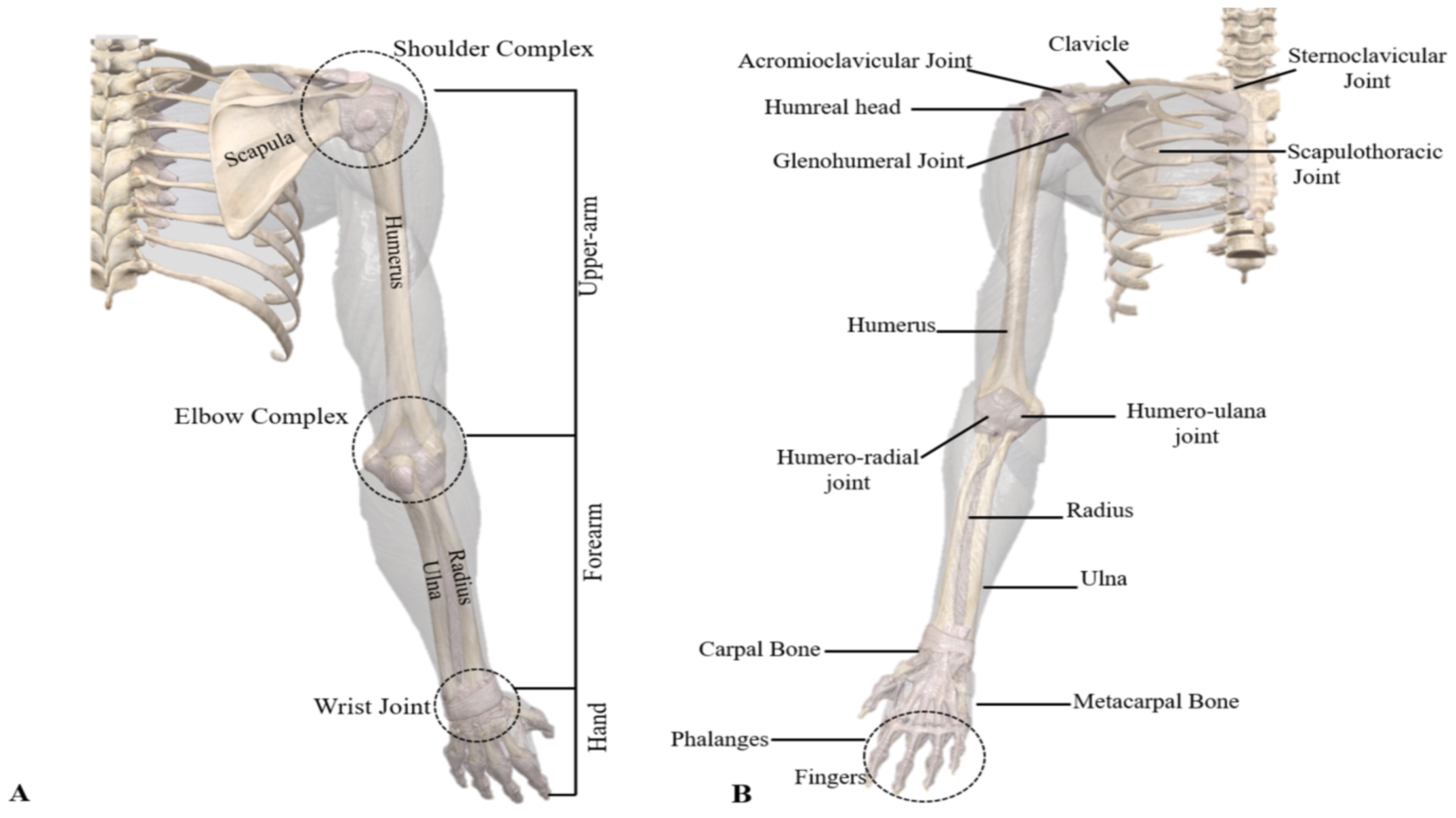
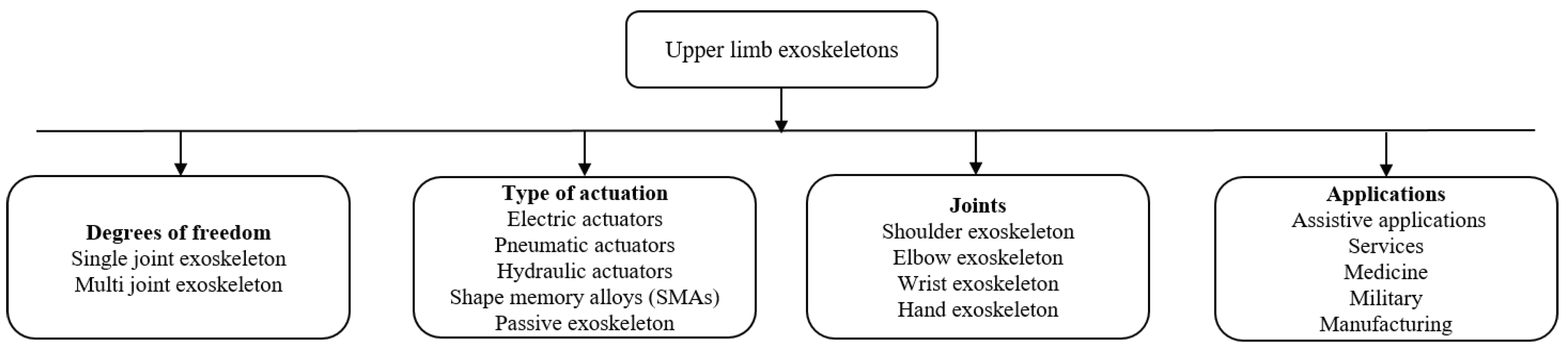
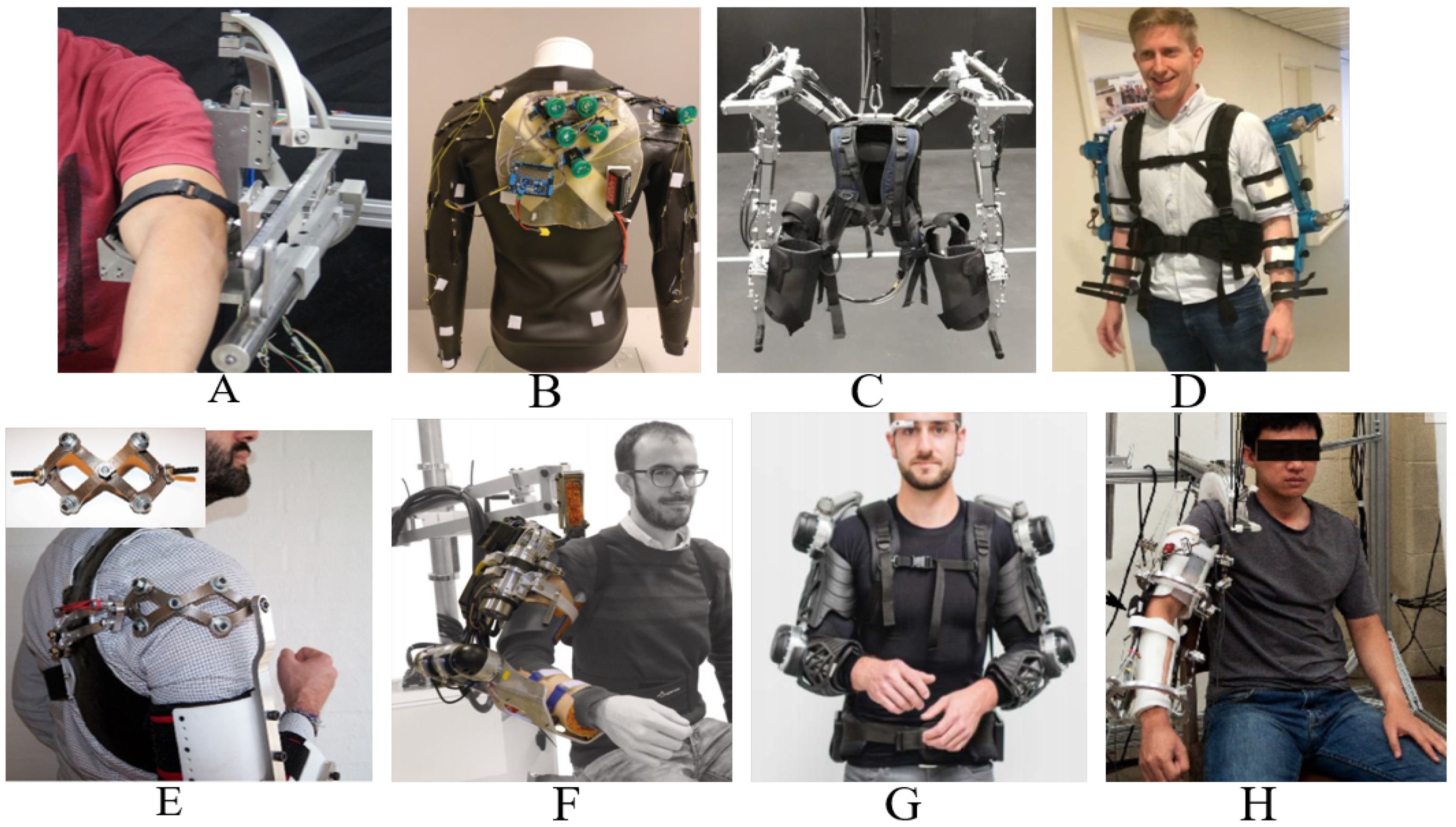
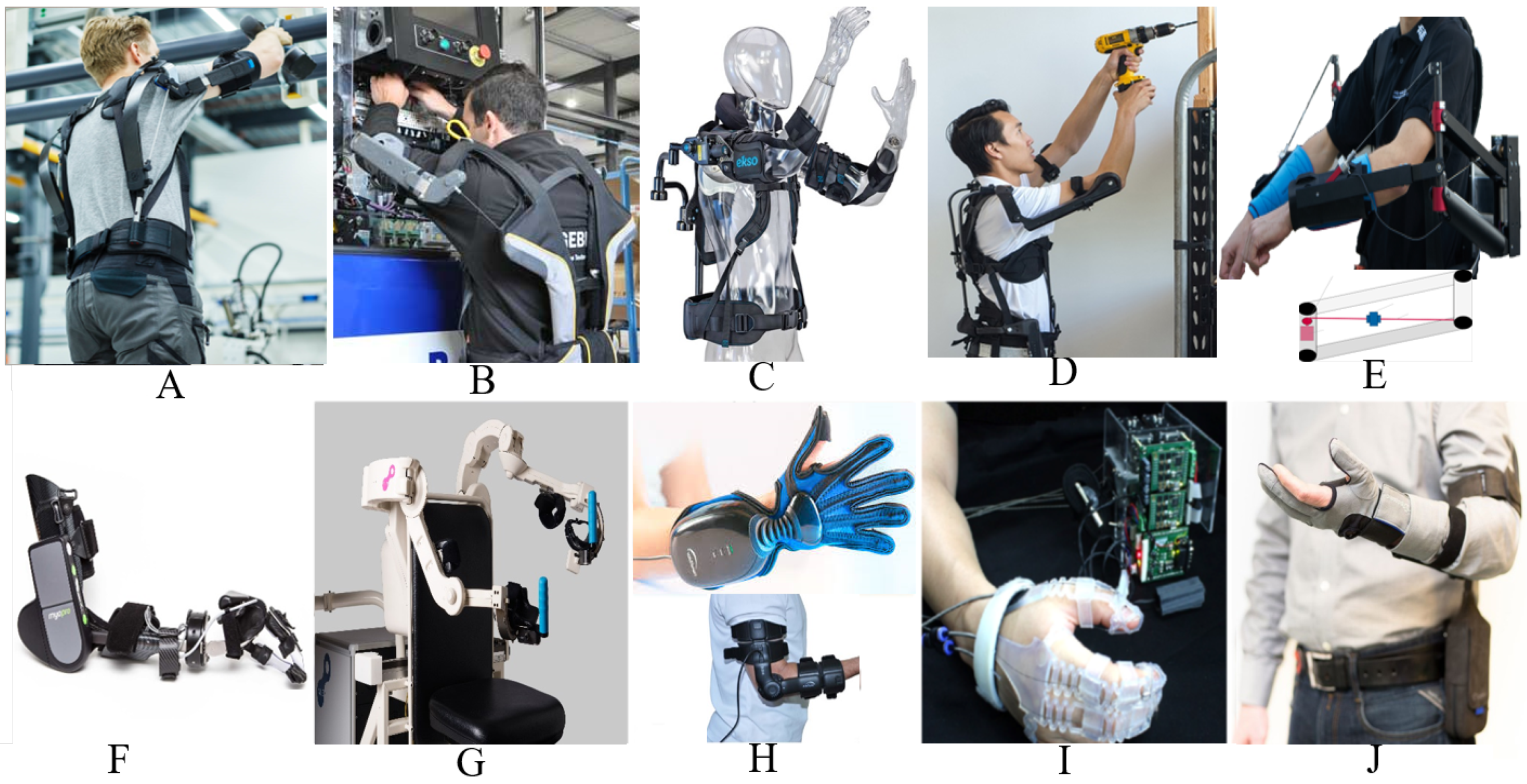
Table 1.
Upper limb exoskeleton prototypes for motion assistance.
| Exoskeleton Name | Supported Movements | Degrees of Freedom | Main Control Input | Type of Actuators | References |
|---|---|---|---|---|---|
| AAU Upperbody Exo. | Shoulder (EF, AA, IE), Forearm (EF) | 3-Active 1-Passive | FSR | Maxon DC motor | Bai et al. [7] |
| Upper limb exoskeleton | Shoulder (EF, AA, IE), Forearm (EF) | 6-Active | Force/Torque sensors | DC motor | Yu et al. [30] |
| CRUX | Shoulder Abduction, Forearm (EF, PS) | 3-Active | Joystick | DC motor | Lessard et al. [42] |
| Wearable upper limb exoskeleton | Shoulder (EF, IE, AA), Elbow (EF, PS) | 5-Active | Joint angle | Cable driven mechanism using BLDC | Sui et al. [32] |
| Stuttgart Exo Jacket | Shoulder (EF, AA), Elbow (EF) | 3-Active 9-Passive | Force Sensors | EC Motor with Spring mechanism | Ebrahimi et al. [46] |
| ULEL | Shoulder (EF), Forearm (EF), Wrist (EF) | 3-Active | EMG | BLDC | Madani et al. [48] |
| Cable driven Soft exoskeleton | Elbow (EF) | 1-Active | Joint angle control | Cable driven | Jarrett et al. [49] |
| Upper limb robotic Exo. | Shoulder (EF, AA, IE), Forearm (PS), Elbow (EF, humeral rotation) | 6-Active | Joint angle | Servo motor | Montano et al. [33] |
| MAHI EXO-II | Forearm (EF, PS), Wrist (EF, rotation) | 4-single DOF 2-Multi DOF | EMG | DC motor | McDonald et al. [50] |
| Upper limb exoskeleton | Shoulder (EF, AA), Forearm (EF, PS) | 3-Active | Joint angle | DC motor | Sharma et al. [34] |
| String actuated exoskeleton | Shoulder (EF), Elbow (EF) | 2-Active | EMG | String actuated | Wahyunggoro et al. [35] |
| Upper limb exoskeleton | Shoulder (EF), Elbow (EF) | 2-Active | Load cell | DC motor | Khan et al. [51] |
| Upper limb exoskeleton | Shoulder (AA, EF, rotation) | 3-Active | - | DC motor | Rosales et al. [52] |
| Upper limb exoskeleton | Shoulder (AA, EF), Forearm (EF) | 3-Active | Impedance control | Servo motor | Mahdavian et al. [53] |
| Upper limb exoskeleton | Shoulder (AA, EF, rotation),Forearm (EF) | 4-Active | Impedance control | Maxon EC 90 | Sutapun et al. [54] |
| CAREX -7 | Shoulder (EF, AA, rotation), Elbow (EF), Wrist (EF, AA, rotation) | 7-Active | Joint angle | Cables driven by motor | Cui et al. [36] |
| 6-REXOS | Elbow (EF, redundant), Forearm (PS), Wrist (EF, UR, redundant) | 4-Active 2-Passive | pHRI | DC motor | Gunasekara et al. [37] |
| Upper limb exoskeleton | Elbow (EF) | 1-Active | EMG | DC motor | Beigzadeh et al. [55] |
| MAHI | Forearm (EF, PS), Wrist (RU, EF) | 5-Active | Admittance control | Frameless DC motor | Fitle et al. [56] |
| BONES | Shoulder (EF, AA rotation), Elbow (EF) | 4-Active | Force control | Pneumatic actuators | Klein et al. [57] |
| ExoRob | Forearm (EF, PS), Wrist (EF, RU) | 4-Active | Sliding mode control | Maxon EC-45 | Rahman et al. [58] |
| ABLE | Shoulder (EF, AA, rotation), Elbow (EF) | 4-Active | Force feedback control | Screw-cable transmission | Garrec et al. [59] |
Abbreviations: AA: Abduction & adduction, EF: Extension & flexion, IE: Internal & external rotation, PS: Pronation & supination, RU: Ulnar & radial movement/deviation, Op/Cl: Opening & closing, MCP: Meta carpophalangeal movement, PIP: Proximal interphalangeal movement, DIP: Distal interphalangeal movement. EMG: Electromyography, sEMG: Surface electromyography, EEG: Electroencephalography, FES: Function electrical stimulation, phRI: Physical human robot interaction, FSR: Force sensitive resistors, BCI: Brain computer interface.
Table 2.
Upper-limb exoskeleton prototypes for medical rehabilitation.
| Exoskeleton Name | Supported Movements | Degrees of Freedom | Main Control Input | Type of Actuators | References |
|---|---|---|---|---|---|
| Upper body Exoskeleton Harmony | Shoulder (EF, AA, IE rotation), 2DOF for Shoulder girdle Elbow (EF, PS) | 7-Active | Trajectory tracking with impedance control | SEA based actuators | Kim et al. [6,63,64] |
| Spastic elbow and wrist Exoskeleton | Elbow (EF) Wrist (EF) | 2-Active | Joint angle | DC Maxon motor | Nam et al. [65] |
| NESM | Shoulder (EF, AA, IE rotation), Elbow (EF) | 4- Active 8-Passive | EMG | Brushless DC motor | Accogli et al. [66] |
| Parallel actuated Exo for shoulder joint | Shoulder pitch and yaw | 2-Active 4-Passive | Force sensors | DC motor | Hsieh et al. [41] |
| Parallel actuated shoulder exoskeleton | Shoulder (EF, AA, rotation), 2-DOF Passive Slip joint at shoulder | 3-Active 2-Passive | Joint angle | DC motor | Hunt et al. [67] |
| NEURO-Exos elbow module | Elbow (EF) | 1-Active | Joint angle | Maxon DC motor | Crea et al. [68] |
| Upper arm exoskeleton | Shoulder (AA, EF), Elbow (EF) | 3-Active | Joint angle | Cable driven | Shao et al. [69] |
| Gravity balanced exoskeleton | Shoulder EF, AA, IE Elbow (EF, PS) | 4-Active 1-Passive | Joint angle | Brushless servos | Wu et al. [70] |
| Wearable elbow exoskeleton | Elbow (EF, PS) | 2-Passive | Joint angle | SMA | Copaci et al. [22] |
| Wearable robotic device | Elbow (EF) | 1-Active | EMG | Twisted string actuation | Hosseini et al. [71] |
| Robotic wrist exoskeleton | Forearm (PS) Wrist (EF, rotation) | 3-Active | Joint angle | Brushed DC motor | Pezent et al. [72] |
| Active elbow orthosis | Elbow (EF) | 1-Active | Strain gauge | Maxon DC motor | Ripel et al. [73] |
| EAsoftM exoskeleton | Elbow (2-Passive DOF) Wrist (2-Active DOF) | 2-Passive 2-Active | Visual based control | Pneumatic actuator | Oguntosin et al. [74] |
| Passive physio therapeutic exoskeleton | Shoulder (AA, EF, rotation), Elbow (EF), Wrist (PS) | 7-Passive | Joint angle | - | Naidu et al. [75] |
| WOTAS | Forearm (PS, EF), Wrist (RU) | 3-Active | Impedance control | Brushless DC motor | Ruiz et al. [76] |
| HEnRiE | 3-DOF Shoulder Elbow (EF), Wrist (EF, AA) | 5-Active | End-effector velocity control | DC motor | Mihelj et al. [77] |
| Under actuated Hand exoskeleton | Under actuated hand (EF) | 4-Active | Joint angle | DC motor | Sarac et al. [78] |
| The eWrist | Wrist extension | 1-Active | sEMG | DC motor | Lambelet et al. [79] |
| ASR Glove | Finger (MCP, PIP, DIP) | 3-Active for each finger | Force sensor | Shape memory alloy | Hadi et al. [80] |
| FEX | Palm (Op/Cl) | 4-Active | Force sensors | DC motor | Sale et al. [81] |
| Portable hand Exo | 4 X Fingers (EF) | 4-Active | Joint angle | DC servo motor | Bianchi et al. [5] |
| BCI powered exoskeleton | 3 X Fingers pinchGrip (Op/Cl) | 1-Active | EEG | DC motor | Bundy et al. [82] |
| Spring assisted hand exoskeleton | Hand Grasping, Wrist (PS) | Not Given | Joint angle | Springs | Butler [83] |
| Spring-assisted exoskeleton module | Fingers (EF), Thumb (EF, AA) | 3-Passive | Joint angle | - | Perry et al. [84] |
| ExoK’ab 2016 | Palm (Op/Cl) | 6-DOF | Force sensors | DC motor | Sandoval et al. [85] |
| NMES-Robot hand | Grasping | Fingers | EMG | Linear actuator | Rong et al. [86] |
| Haptic robotic glove | Grasping | All Fingers | FES | Pneumatic drive | Hartopanu et al. [87] |
| Hand motion assist robot for therapy | Wrist and fingers | 18-DOF | - | - | Kawasaki et al. [88] |
| Hand exoskeleton | Grasping, pointing & pincer | 6-Active 6-Passive | Admittance control | Bowden cables with BLDC | Ferguson et al. [89] |
| Myoelectric Hand Exoskeleton | Hand (Op/Cl) | 5-Active 10-Passive | EMG | Servo motor | Abdallah et al. [90] |
| Robot-assisted wrist | Wrist (FE) | 1-Active | EMG | - | Hu et al. [91] |
Table 3.
Commercially available upper-limb exoskeleton systems.
| Company | Product | Application | Reference |
|---|---|---|---|
| RoboMate | Passive parallelogram arm Active parallelogram arm | Assistance power amplification | Stadler et al. [60] |
| GOBIO | Ergosquelettes | Assistance | www.gobio-robot.com [99] |
| Ekso Bionics | EksoVest | Passive Assistance | https://eksobionics.com/eksoworks/ [38] |
| SARCO | Guardian XO | Assistance | www.sarcos.com/products/guardian-xo/ [39] |
| SUIT X | MAX | Assistance (Reduce force at back shoulder) | www.suitx.com [100] |
| RB3D | Hercule Exoskeleton | Assistance (Industrial tool handling) | www.rb3d.com/en/exoskeletons [105] |
| BioServo | Iron hand & SEM glove | Assistance/rehabilitation | Nilsson et al. [4] |
| Rehab-Robotics | Hand of hope | Post stroke rehabilitation | www.rehab-robotics.com/index.html [106] |
| FOCAL meditech | Dynamic arm support | Rehabilitation | Meditech dynamic [94] |
| Kinetek | ALEx Arm | Assistance/rehabilitation | www.wearable-robotics.com/kinetek [102] |
| MediTouch | ArmTutor | Rehabilitation | Carmeli et al. [3] |
| Motorika Medical | ReoGO | Therapy | www.motorika.com/reogo [107] |
| REHA Technology | Armotion | Therapy | www.rehatechnology.com/en/products/armotion [108] |
| Tyromotion | AMENDEO Hand | Therapy | tyromotion.com/en/ [109] |
| BIONIK | InMotion Arm | Therapy | Robot et al. [110] |
| Myomo | MyoPro Orthosis | Therapy | www.myomo.com [101] |
Table 4.
Control strategies used in the recent exoskeleton robots.
| Sr. | Assistive Mode | Corrective Mode | Resistive Mode |
|---|---|---|---|
| 1. | Passive control a. Passive trajectory tracking b. Passive mirroring | Tunneling | No control development for exoskeletons |
| 2. | Partially assistive control a. Impedance/admittance control |
© 2020 by the authors. Licensee MDPI, Basel, Switzerland. This article is an open access article distributed under the terms and conditions of the Creative Commons Attribution (CC BY) license (http://creativecommons.org/licenses/by/4.0/).
Share and Cite
MDPI and ACS Style
Gull, M.A.; Bai, S.; Bak, T. A Review on Design of Upper Limb Exoskeletons. Robotics 2020, 9, 16. https://doi.org/10.3390/robotics9010016
AMA Style
Gull MA, Bai S, Bak T. A Review on Design of Upper Limb Exoskeletons. Robotics. 2020; 9(1):16. https://doi.org/10.3390/robotics9010016
Chicago/Turabian StyleGull, Muhammad Ahsan, Shaoping Bai, and Thomas Bak. 2020. "A Review on Design of Upper Limb Exoskeletons" Robotics 9, no. 1: 16. https://doi.org/10.3390/robotics9010016
Note that from the first issue of 2016, this journal uses article numbers instead of page numbers. See further details here.