
Design of Dihedral Bows: A New Type of Developable Added Bulbous Bows—Experimental Results

1
Department of Naval Architecture, Universidad Politécnica de Madrid (UPM), 28040 Madrid, Spain
2
Department of Mechanical Engineering, Universidad de Las Palmas de Gran Canaria (ULPGC), 35014 Las Palmas de Gran Canaria, Spain
*
Author to whom correspondence should be addressed.
J. Mar. Sci. Eng. 2022, 10(11), 1691; https://doi.org/10.3390/jmse10111691
Submission received: 28 September 2022
/
Revised: 14 October 2022
/
Accepted: 17 October 2022
/
Published: 8 November 2022
(This article belongs to the Special Issue Maritime and Ship Design)
Abstract
:This paper presents the design and the experimental results of a new type of developable added bulbous bow that has been designated as a dihedral bow. This type of bow is based on polyhedral bows that are used in small vessels, whose origin is traced to the 1990s. The bow is designed with a set of developable surfaces that are designed following previous methodology on surface design that considers material properties and can contain boundary curves. Two dihedral bow designs and their towing tank tests are presented in this work. A displacement and a semi-displacement hull were tested in two different loading conditions and for different Froude numbers. An important reduction of the effective power (PE) of the ships with the dihedral bow was observed during the experiments. There is a reduction of about 20% for the displacement hull and about 16% for the semi-displacement. The design methodology for the dihedral bows is presented in this paper together with experimental results on power, sink and trim. Dihedral bows are a good option for efficient small ship design, as well as larger ships.
1. Introduction
A polyhedral bulbous bow is a type of bulbous bow that is quite similar to the beak bow that is present on some large ships, but the main difference is that the polyhedral bow pierces the water surface and is not fully submerged. Therefore, these bows are sometimes erroneously referred to as wave piercing bows.
A polyhedral bulbous bow has chine lines incorporated into its definition, making this bow easier to produce and enabling the retrofitting of designs without a bulbous bow, reclassifying them as added bulbous bows. These chine lines also mark the hydrodynamic properties of the bow.
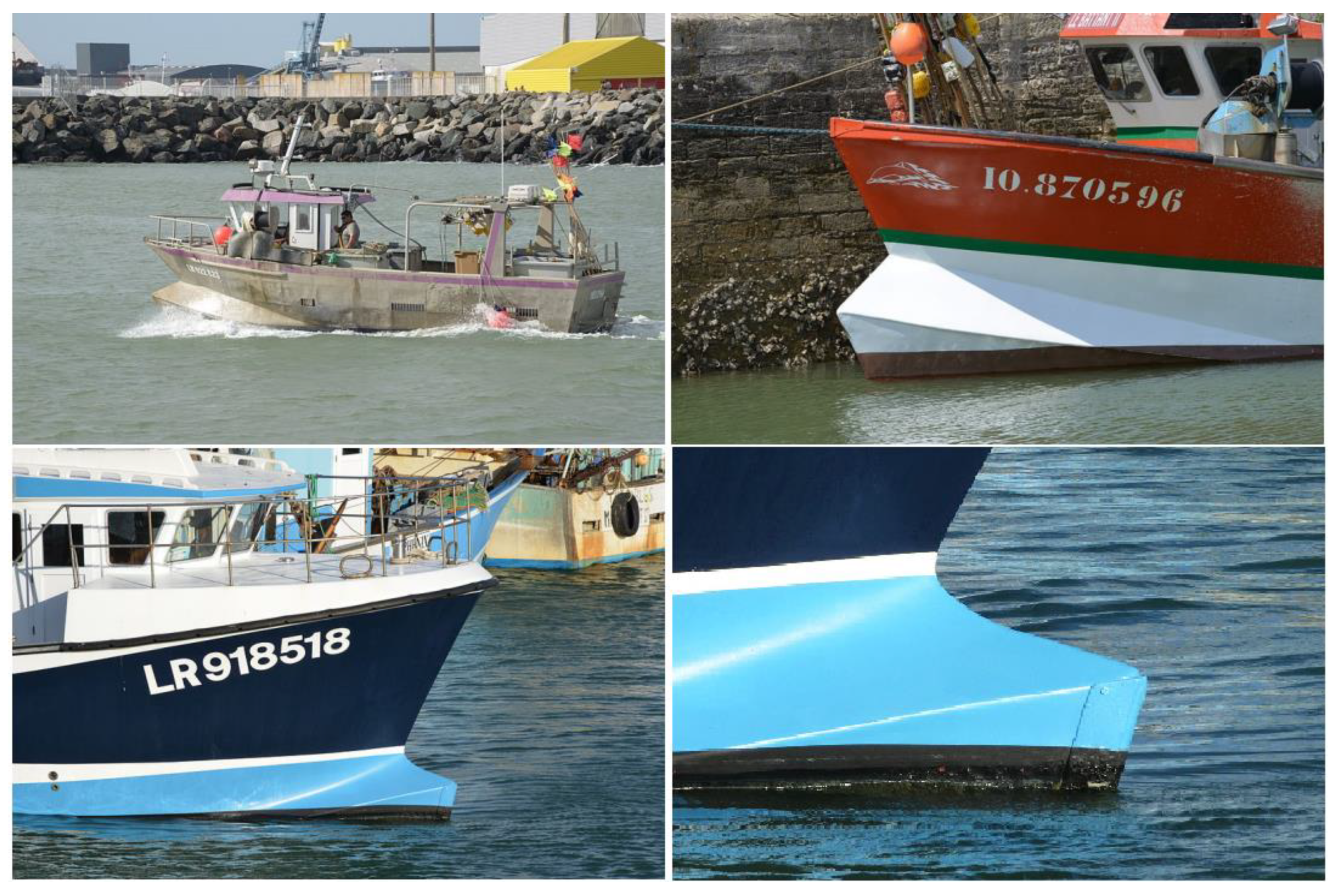
The shape of a polyhedral bow is quite distinctive and can be well-integrated into the original design or as an addition to the hull. A good example is represented in Figure 1. The ship on the top left is constructed in metal and the bulbous bow appears to be an addition. The ship on the top right is constructed in GRP (Glass Reinforced Plastic) and the bulbous bow was integrated into the mold during construction.
The chine lines can be incorporated into the design as in these examples, or can be softened when the bulbous bow is integrated into the design and the ship is produced through mold construction, as demonstrated in the ship at the bottom of Figure 1.
The origins of these types of ship bows can be traced to the 1990s when some rescue and pilot boats in France were designed as double chine hulls with a forward polyhedral bow. These ships combine several advantages: finer entry in the forward sections, efficient spray rails to keep the deck dry and diminishing motions in heavy seas due to a more sea-friendly shape in the forward slamming area. The chine shape at the aft end also gives stability in rough seas. These distinctive ships are also known as Pantocaréne hulls, named by the French designers that started using this design in the 1990s.
The chine lines can be marked into the design as in the ships at the top of Figure 1, or softened when the bulbous bow is integrated into the design and the ship is produced through mold construction, like the ship in the bottom of Figure 1.
The origins of this type of ship bow can be traced to the 1990s when some rescue and pilot boats in France were designed as double chine hulls with a forward polyhedral bow. These ships combine a number of advantages, including finer entry in the forward sections, efficient spray rails to keep the deck dry and diminishing motions in heavy seas due to a more sea-friendly shape in the forward slamming area. These distinctive ships are also known as Pantocaréne hulls, named by the French designers that started using this design in the 1990s.
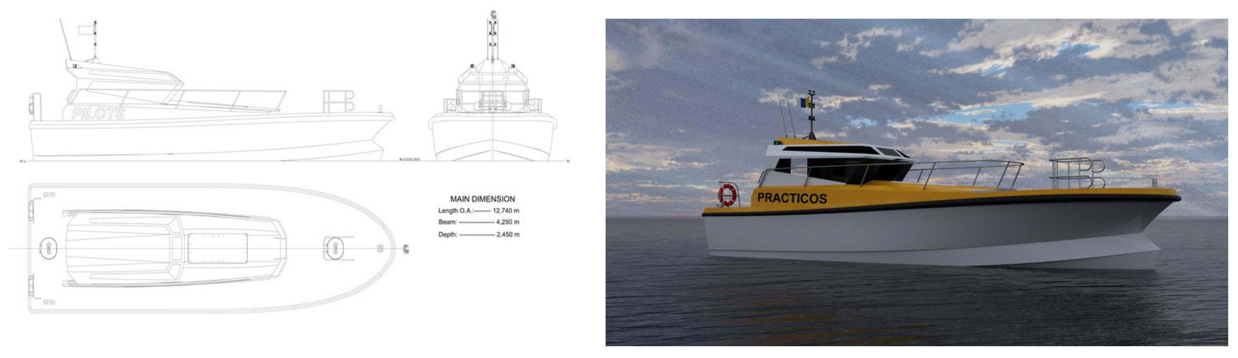
The difference with the new type of bulbous bow presented in this paper is that the Pantocaréne hulls are designed to fit in a double chine hull as depicted in Figure 2, while the polyhedral bow can fit in single chine hulls or even round bilge hulls.
A polyhedral bulbous bow is not completely submerged as conventional bulbous bows are. A conventional bulbous bow produces interference waves that diminish the wave resistance, while a polyhedral bow improves the flotation and increases the ship’s fine entrance with a semi angle of about 20°, cutting the water surface and diminishing the intensity of the diffracted waves.
This paper presents the design of added polyhedral developable bows, that will be named dihedral bows. This paper is focused on still water since the presented application examples are small boats that have not been designed for open seas, but navigate in lakes or shelter waters and stay in port during bad weather. This paper presents two ships proposed by the FAO (Food and Agriculture Organization of the United Nations) in its small ship data base [1]. Dihedral bows are designed for these ships using developable surfaces.
Although seakeeping has not be considered in this research, Pantocaréne ships have proven to having excellent seakeeping ability: the bulbous bow volume dampens the vertical motions and, when fully submerged, the shape of the bow increases pitch dampening, reducing vertical acceleration.
Another advantage of the dihedral bow is that the dynamic trim angle is reduced when compared to ships without a bulbous bow, since the fine entrance reduces the vertical pressures, a critical element when speed increases. This is why these bows work well in both displacement and semi-displacement ships, as is presented in the results in Section 4.
Of minor importance regarding resistance, but with a high impact on comfort aboard, the dihedral shape reduces the spray because the water is deflected in the chine and is deflected away from the hull.
A good design of a dihedral bow together with a balanced design of the hull and appropriate positioning of the center of gravity can produce a very good boat when compared with a ship without a bulbous bow.
An analysis of the current literature has shown no results regarding polyhedral bows. Reference [2] addresses developable surfaces in ship design in more detail; however, the focus of our research is ship design. Regarding bulbous bow design, the most important published works started in the last century and are the experimental work of Kracht in 1978 [3] and the theoretical works of Yim in 1974 [4] and Yim in 1980 [5]. Bulbous bow design is associated with the reduction of fuel consumption as demonstrated by [6,7].
This paper demonstrates that using a dihedral bow saves power, up to 20% in some cases. A standard bulbous bow was designed for an FAO fishing vessel in [8], obtaining reductions in the effective power (PE) of about 14%. An optimized bulb may produce the bow waves that interfere positively with the waves generated by a hull, resulting in a reduction in PE by about (12~15)% [9]. Large ships with bulbous bows generally have 12–15% better fuel efficiency than similar ships without bulbous bows, according [10]. With the use of a dihedral bow, higher PE reductions have been achieved, as described in Section 4.
Regarding the geometric design of the bulbous bow surface, there are only a few references that parametrically define the surface and most of them use B-spline curves and surfaces, as demonstrated by [11,12].
Considering the previous literature, the novelties of this study are the new design of bulbous bows with developable surfaces that are defined through significant curves and the important effective power reduction that is achieved. A key difference from the conventional bulbous bow is that the dihedral bow is not fully submerged.
2. Defining a Developable Polyhedral Bulbous Bow: The Dihedral Bow
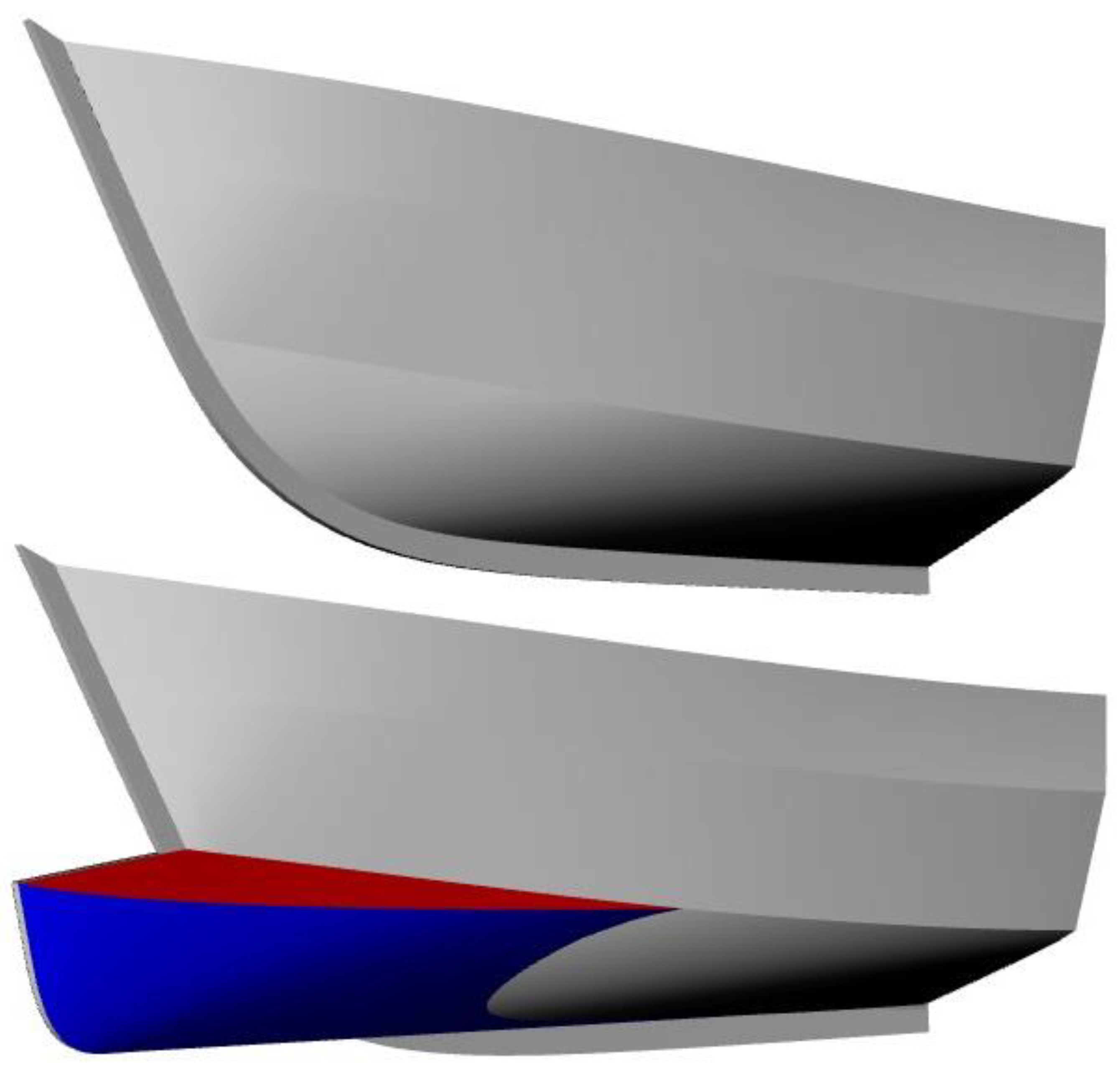
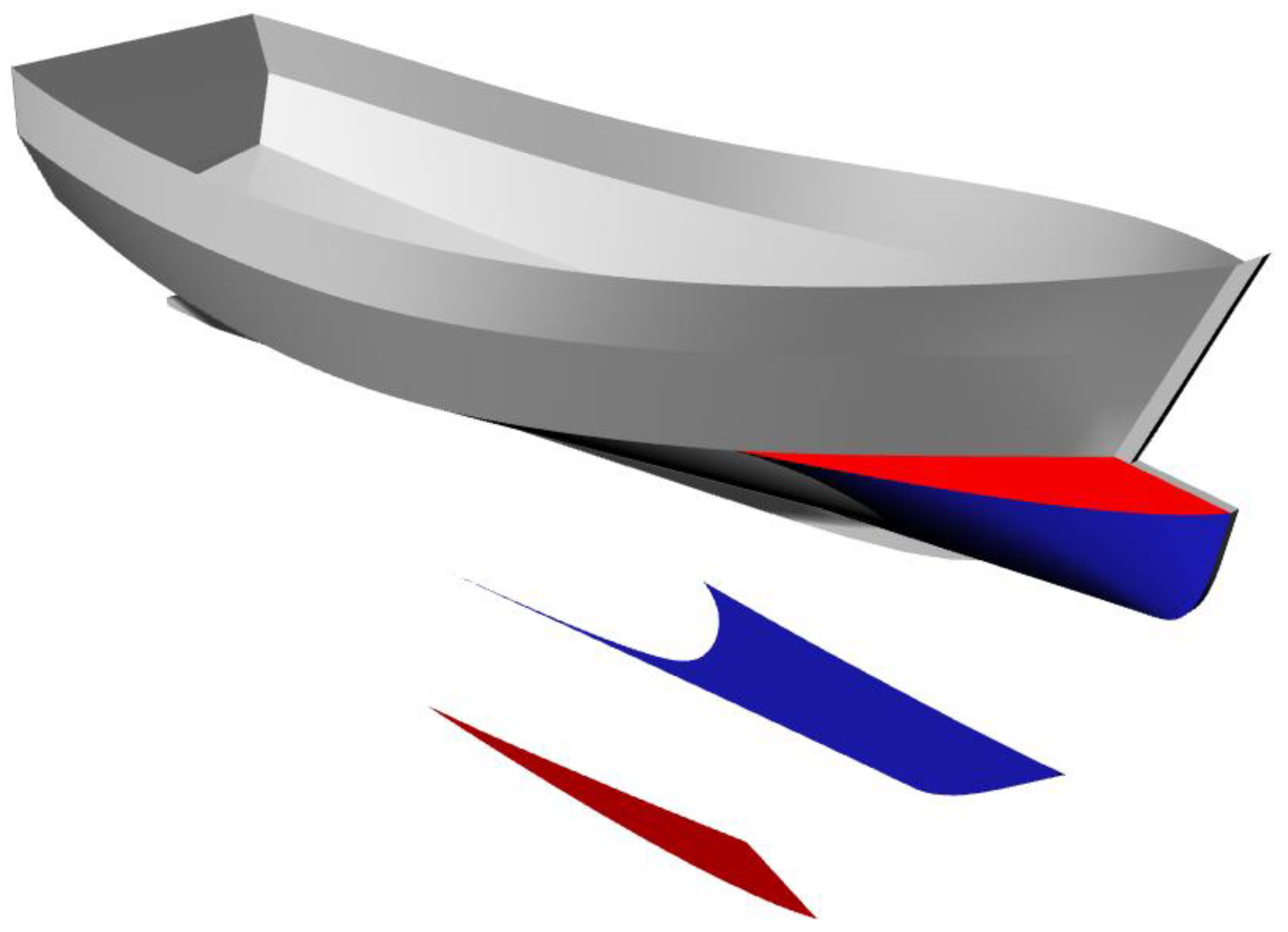
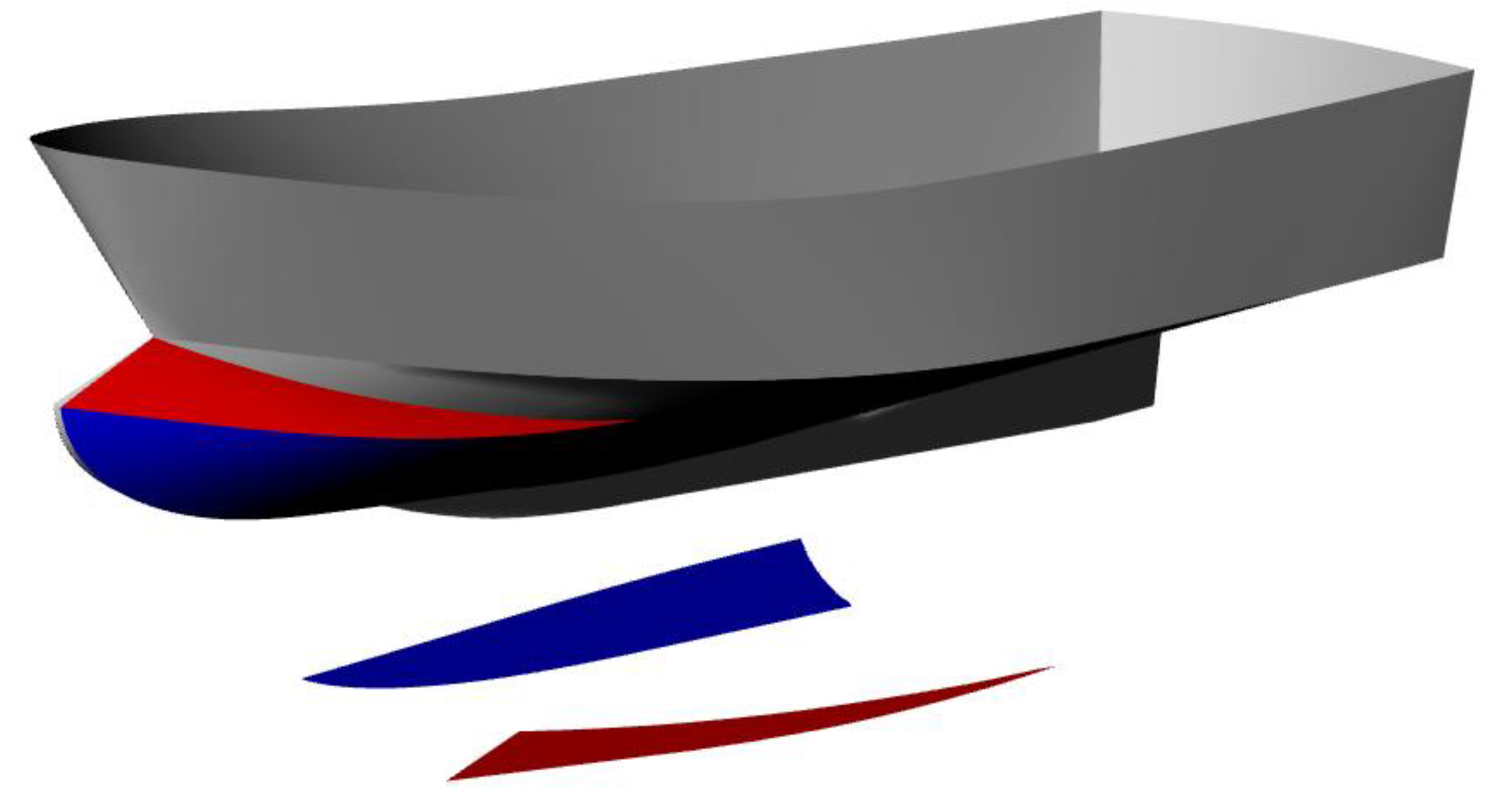
A dihedral bow is mainly defined by two new surfaces that are added to the hull definition. This is shown in Figure 3 where the red area is the upper surface and the blue one is the lower surface. The keys to defining these surfaces are to consider some representative curves into its definition and to define a developable surface that contains these curves. The full methodology to define a ship hull developable surface that contains two directrices curves is described by the authors in [2].
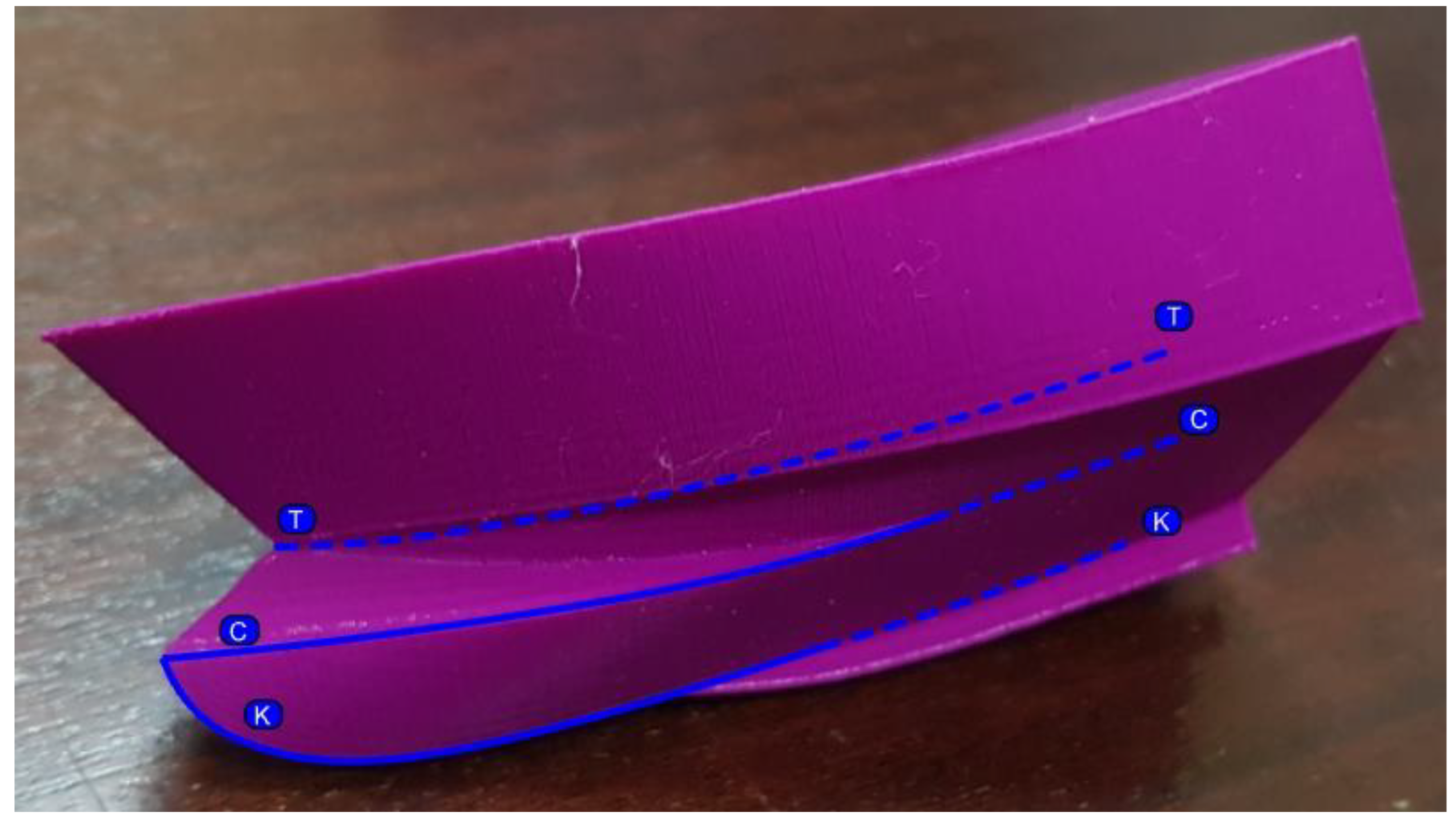
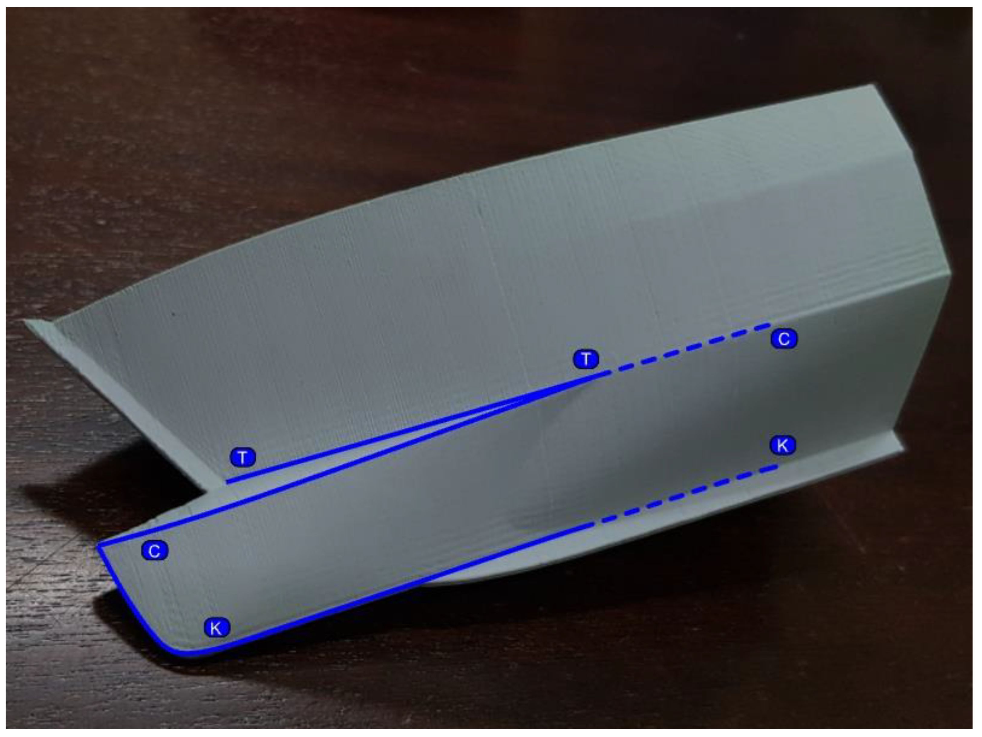
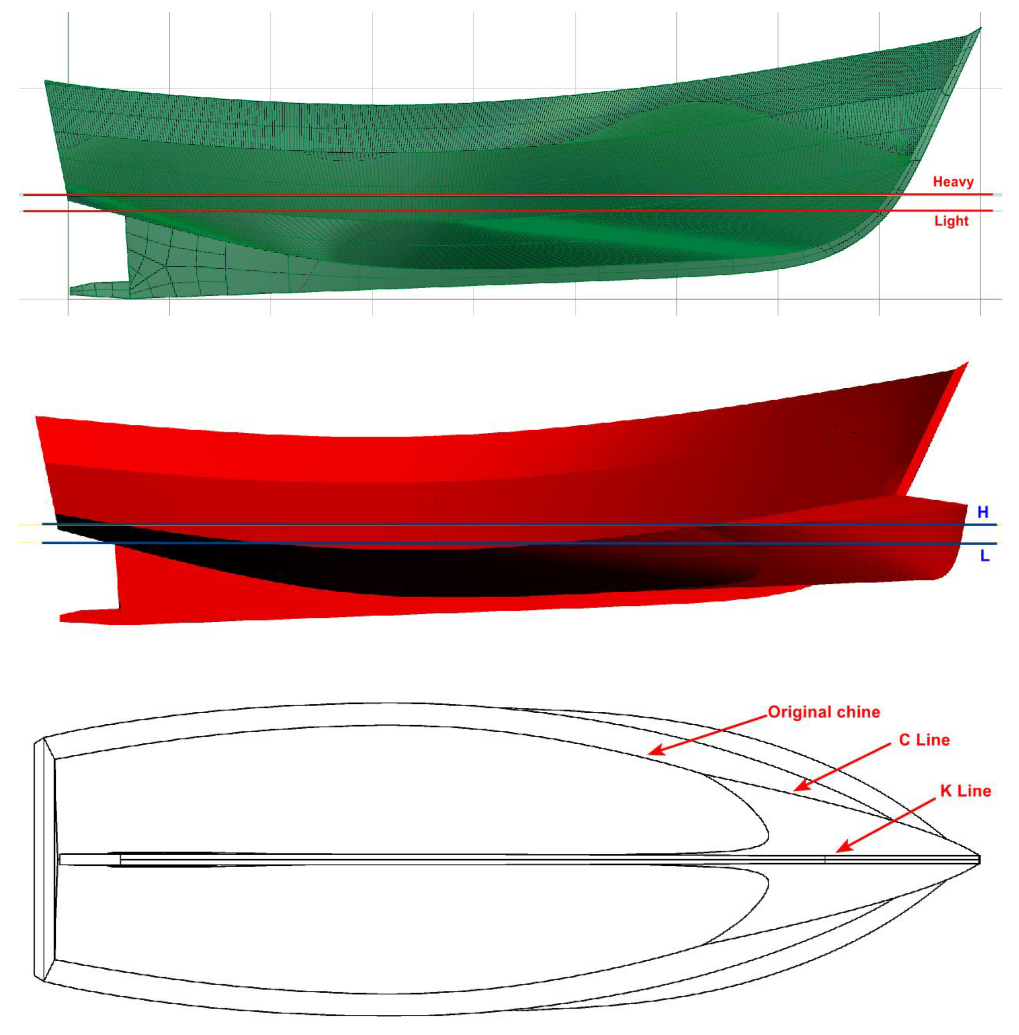
Some examples of these representative curves can be seen in Figure 4 and Figure 5. The lower surface is defined by a curve that is called the Keel line (K) as well as the Chine line (C), while the upper surface contains the C line and Top curve (T). The curves are dashed when they are inside the original hull volume, and continuous when they are outside.
Therefore, the key for the design of a dihedral bow is to consider the shape of these characteristic curves instead of the surface itself. Faired curves indicate that the developable surface that contains them is faired. These curves also mark the hydrodynamic behavior of the design.
The K line should be well-integrated with the shape of the keel in the original hull, and its shape marks the waterline length increment with the bulbous bow. If the original hull has a keel, the K line should be designed to adapt to the width of the keel.
The C line marks the top end of the lower surface, and the width of C controls the waterline entrance angle on the bulbous bow. If the original hull has chines in its definition, the C line should be well-integrated with their shape. This does not mean that the chine curve of the bulb hull must be tangent to the one in the original hull, since this is not always possible. In Figure 3 and Figure 5, the chine continuity is maintained, which is also the case in the Pantocaréne hulls (Figure 2). Nevertheless, a good dihedral bulb can be designed without this continuity, as in Figure 4.
The T line sets the top end of the upper surface and starts at the ship’s centerline in relationship to the keel. There are two ways of defining this curve: it can be contained in the ship hull, as in Figure 5, which is the best way to connect the chine of the dihedral bow with the one of the ship hull; or it can be defined inside the ship hull, which allows more freedom in the design of the upper surface, as in Figure 4.
The two surfaces will produce intersection curves with the original hull. The upper surface will produce a sharpened and well-marked curve that will not touch the water surface. The lower surface intersects with the hull in another curve that can be very soft, as in Figure 4, or slightly marked, as in Figure 5. Since the intersection curves are a consequence of the dihedral bow definition, they can be used to test a good design, especially the lower intersection, which will be submerged and must be a soft curve without bumps or hollows.
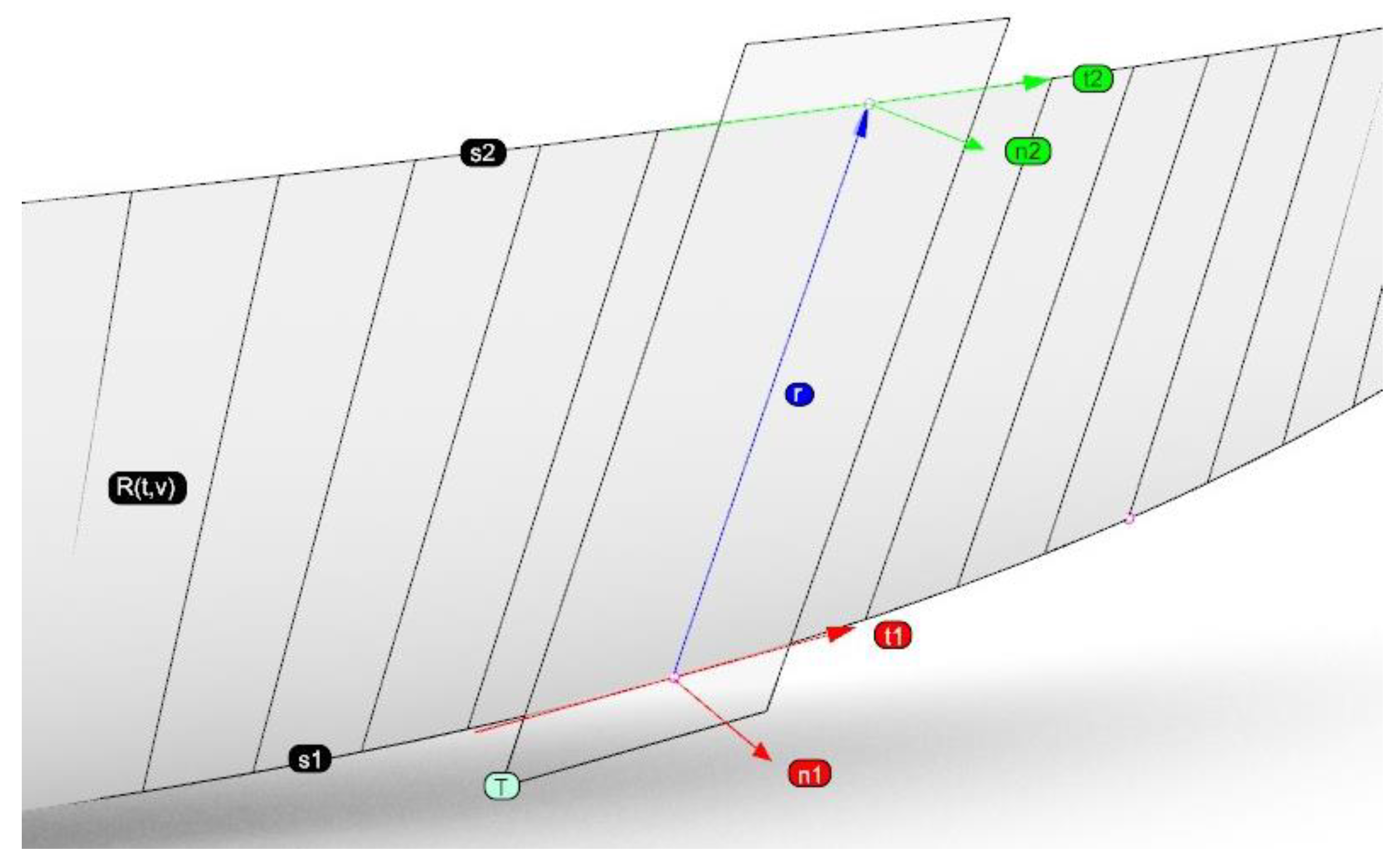
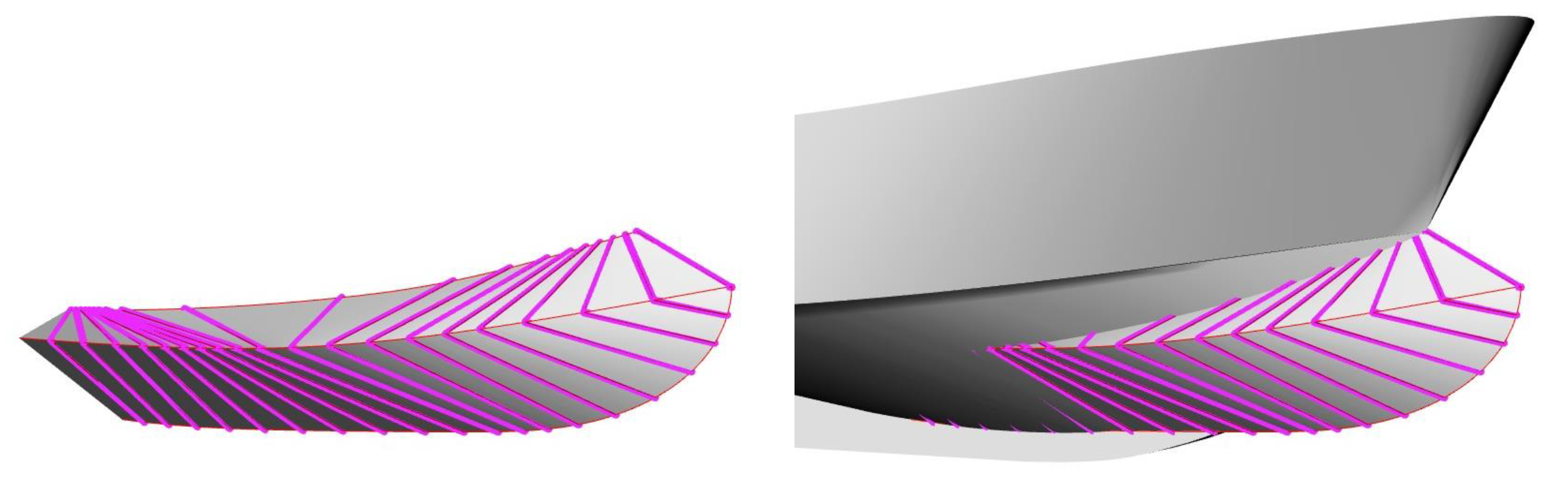
As described in [2], a developable surface can be obtained containing two directrices curves s1 and s2 (see Figure 6) by obtaining different ruling segments r that are contained in the surface. A straight segment is a ruling if the normal vectors at its ends n1 and n2 are parallel. Reference [2] explains a numerical technique to obtain these rulings while also considering the material properties.
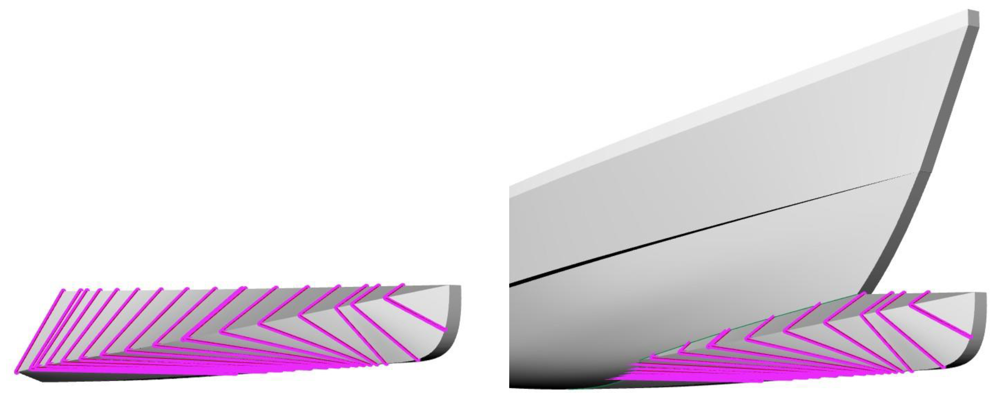
In the case of a polyhedral bulbous bow, the directrices curves would be s1 = K and s2 = C for the lower surface, and s1 = C and s2 = T for the upper surface. The rulings of these sets of surfaces can be obtained while connected, producing the results that are showed in Figure 7. These rulings also have a construction purpose, since they indicate the segments bending to conform to the surface in the ship.
In summary, once the directrices curves K, C and T have been designed, the rulings can be defined numerically and two lofting surfaces containing these segments can be obtained. The upper and lower surfaces are now designed and the intersection with the original hull can be computed with the use of a CAD software, producing the final geometry.
3. Example Designs of Two Dihedral Bows
Dihedral bows have been designed for two different ships and their effectiveness in reducing the power is demonstrated based on towing tank tests of the original hulls first without a bulbous bow, then considering a dihedral bow.
These two ships have been supplied by FAO from its fishing vessels data base [13,14]. They were designed in the 1980s for promoting fishing resources in developing countries. With the addition of a dihedral bulbous bow an important reduction in power, and therefore in fuel consumption, can be obtained, producing more efficient and cost-effective boats that can have a great social benefit in certain developing areas. This was also the main motivation behind this research.
Tests were made with the same draft and zero trim between the ships with and without the dihedral bow. The most significant shape parameters are displayed in Table 1 and Table 2. FAO2 and FAO4 include a dihedral bow.
Slenderness: LWL/Displacement^(1/3)
Alfa(º): Waterplane entrance semi-angle.
Block coefficient: CB = Displacement/(LWL·BWL·T)
Area coefficient: CX = Midship Submerged Area/(LWL·BWL)
Prismatic coefficient: CP = CB/CX
Waterplane coefficient: Waterplane area/(LWL·BWL)
3.1. Example of a Displacement Hull
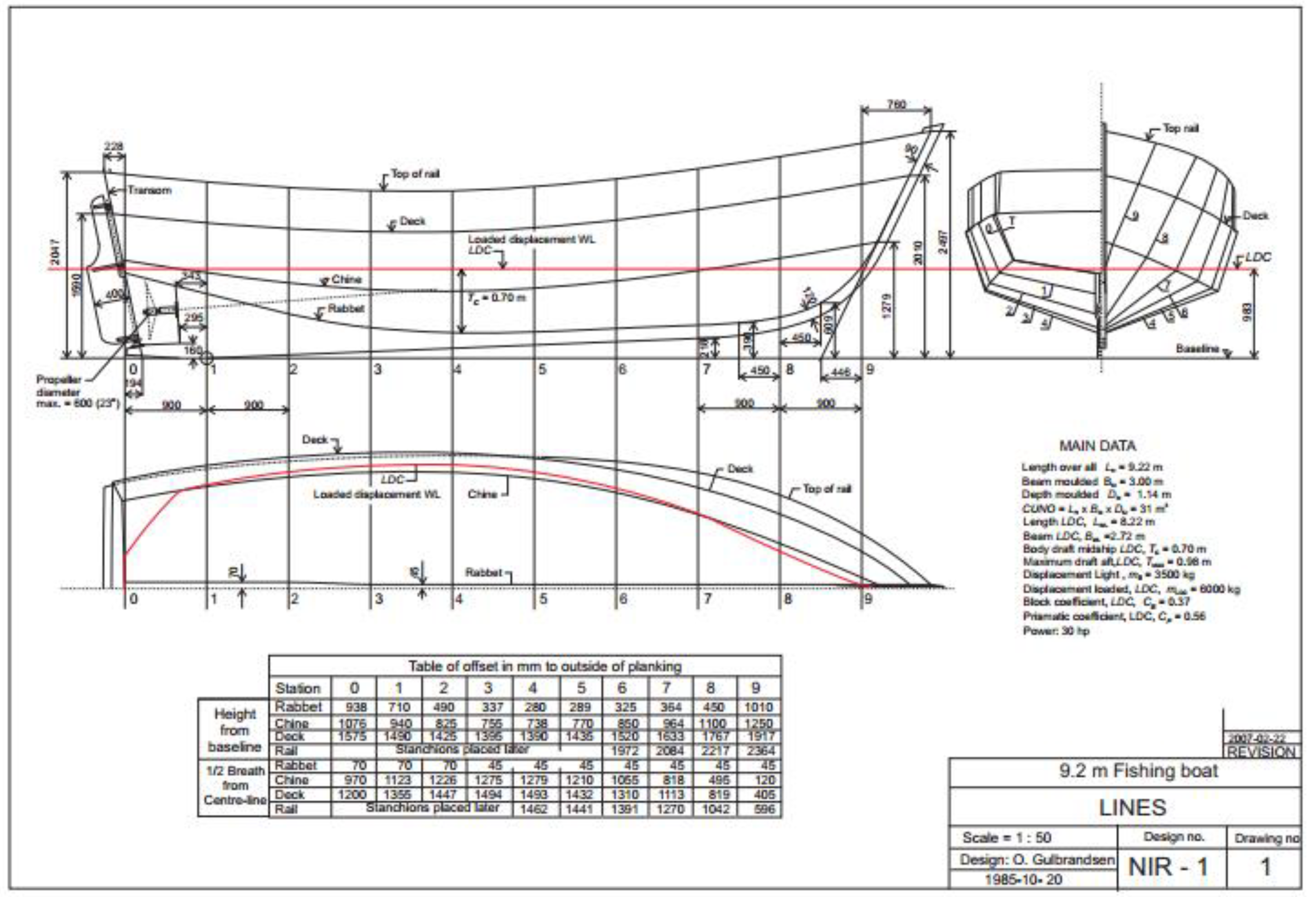
Example one (FAO1) appears in Figure 8. This 30 ft fishing boat was designed in the 1980s to operate in Nigeria. She was constructed in wood, which is why the large keel is included in order to strengthen the hull. This keel must be integrated into the dihedral bow design. Although the design includes chine lines and may resemble a fast ship, the vessel operates in displacement mode and the chines were included, not for hydrodynamic purposes, but for enabling the boat construction in wood.
For this example, curves K, C and T in Figure 5 were designed as follows:
The dihedral bow design integrates the chine (C and T lines) into the chine of the original hull since the ship was narrow enough to enable this combination, which may not be possible in other cases, such as example 2, which is a wider boat searching for a better planing attitude at high speeds.
The keel line K is integrated into the original one, so the bulbous bow will have a keel part that can be constructed with a solid wood board that joins with that of the hull. The bow profile of the keel was oriented almost vertical since the dynamic trim was not high. This is a displacement vessel and the dihedral bow will not emerge during navigation. The waterline length is enlarged, diminishing wave-making resistance and reducing the waterline entrance angle. The top curve T was selected over the original hull since the C line was connected with the chine. A soft curve following the isoparametric curves of the hull was selected. Considering these three curves, the rulings for the bulb are depicted in Figure 8. With these lines, the developable surfaces that contain pairs of directrix curves K and C, as well as C and T can be defined in Figure 9.
The use of a developable surface enables easy plate construction, as the different surfaces that define the dihedral bow can be unrolled without tearing or stretching. The two main surfaces of FAO2 can be seen in Figure 10.
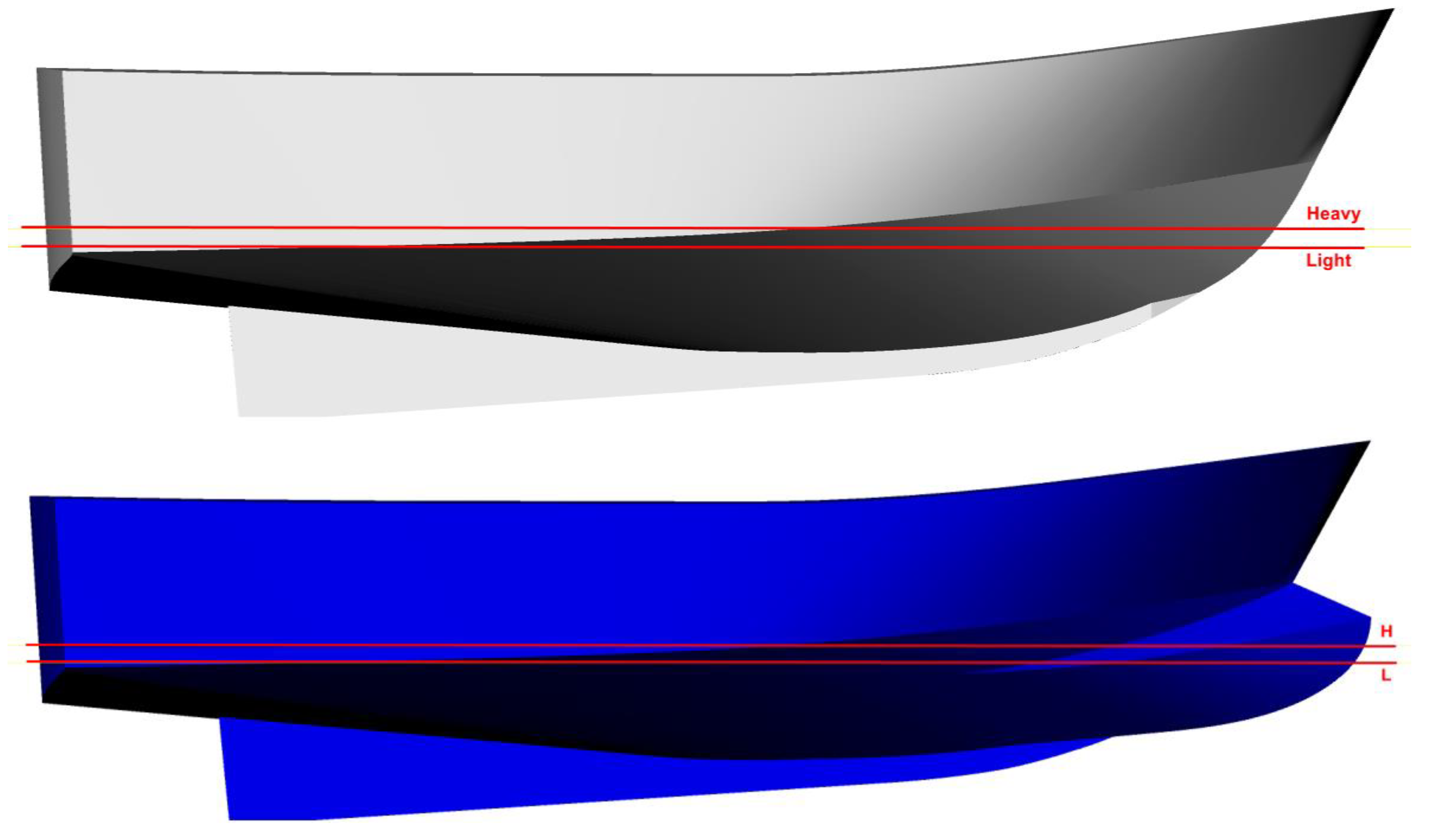
A comparison between the original FAO1 and FAO2 (with the dihedral bow) is presented in the next figure. The loading conditions that were tested in the model basin (see Section 4) are also presented in Figure 11. Notice in the last image of this figure how the C line is inserted with continuity of the original chine. The T line also demonstrates this continuity in the profile view presented in the second image.
3.2. Example of a Semi-Displacement Hull
Example 2 (FAO3) appears in Figure 12. This 25 ft fishing boat was built and is operated in the British Virgin Islands. She was constructed in FRP (Fiber Reinforced Plastic), and the chine hull is hard since it is a semi-displacement vessel designed to operate in high Froude numbers. This example presents a wider chine than the previous example, creating dynamic forces at higher speeds. In this case, the bulbous bow was not integrated into the original chine in order to obtain a finer waterline entrance.
This ship also has a keel that is continued aft into the skeg. the dihedral bow maintains the continuity of this keel with the K line. In this case, the beam of FAO3 is wider than FAO1 and the C line is not integrated into the chine to avoid a high waterplane entrance angle. C and T lines are designed parallel to the original chine when projected from the top and do not maintain continuity as in the previous example.
Once K, C and T lines have been designed, the consequent ruling lines are defined as displayed in Figure 13. Differing from the previous example, C and T lines do not intersect in this case since continuity with the original chine is not maintained. The methodology to create a developable surface works well and both surfaces are designed successfully. The unrolled parts that compound the dihedral bow are showed in Figure 14.
4. Experimental Power Results in Towing Tank
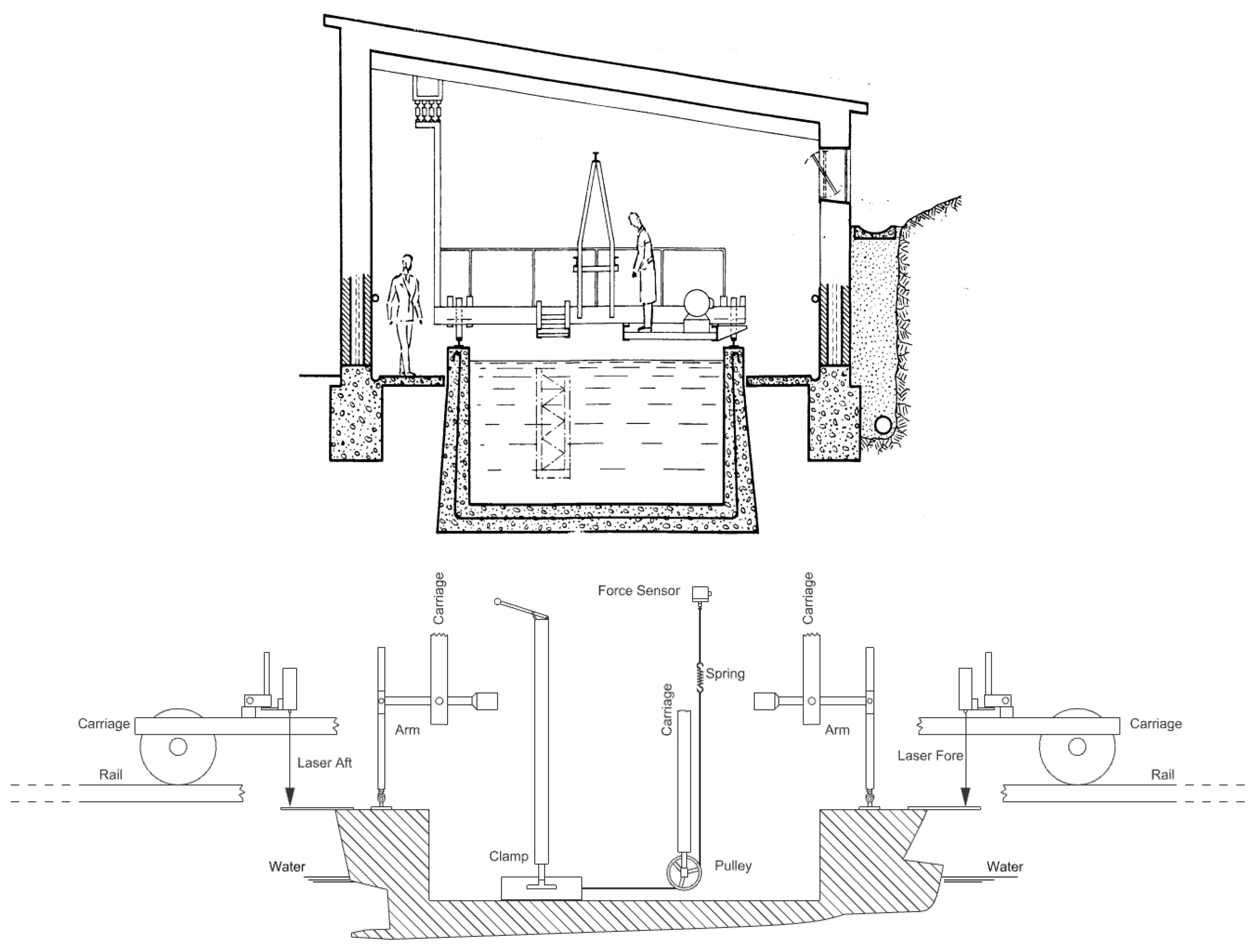
The four designs presented in the previous section were tested in the model basin of the Naval Architecture and Marine Engineering School of Madrid (ETSIN), and were constructed with a scale factor of 4. The towing tank was inaugurated in 1967 with dimensions of 56 m long (later lengthened to 100 m), 3.8 m wide and 2.2 m deep. In Figure 16, a transverse section of the tank is presented. The towing tank is equipped with a running carriage capable of achieving a maximum speed of 4.0 m/s.
Figure 16 shows a schematic of the test setup. The model is connected to the towing carriage by two guiding arms, one wire, one spring and one force sensor. Before each test, the zero reading of all measuring instruments was taken. The zero reading was also checked between runs. The minimum wait time between consecutive runs was set to 20 min to obtain comparable conditions. The water level was also regularly checked to maintain a constant value during the tests. The water temperature was measured at 16 °C to extrapolate the results to full scale according to ITTC 2017 in [15].
Each test was started by accelerating the towing carriage up to the required speed that is the abscissa of Figure 17, Figure 18, Figure 19 and Figure 20. During the acceleration phase, a clamp held the model to avoid excessive stress on the force sensor. The guiding arm system allowed the model to pitch, heave and surge, with other motions restricted. Two laser beams placed aft and fore, enabled the measurement of the trim angle and the sinkage of the model.
The model was fixed in the center line of the towing tank. The tow force was measured with a force sensor (Z6 bending beam load cell) directly attached to the carriage through a calibrated pulley–spring–wire system. The load cell uses a sampling rate of 10 Hz for measuring the resistance. The direction of the towing force was parallel to the advance direction. The measurement at each speed was obtained by averaging the time interval of the signal as described in [15]. The dynamometer was calibrated to a greater range than the maximum model measured resistance (4 kg).
For the prediction of the effective power of the ship from tests carried out in the towing tank, the ITTC-2017 method of [15] has been used. Two loading conditions, heavy and light, were tested and are shown in the profile views of Figure 11 and Figure 15.
In this methodology, the viscous and wave-making resistance components in the model are calculated using the results from the resistance tests, assuming that the “form factor” is independent of the scale and speed. In [15] extrapolation method, the total resistance coefficient is given by the following expression:
where:
Cts = (1 + k)·Cfs + Cw + ΔCf + Ca + Cair
- k: Form factor
- Cfs: Ship friction coefficient given by the ITTC-57 equation, 0.075/(log Rn − 2)2
- Cw: Wave-making resistance coefficient
- Crug: Roughness allowance
- Ca: Correlation allowance
- Cair: Air resistance coefficient in full scale.
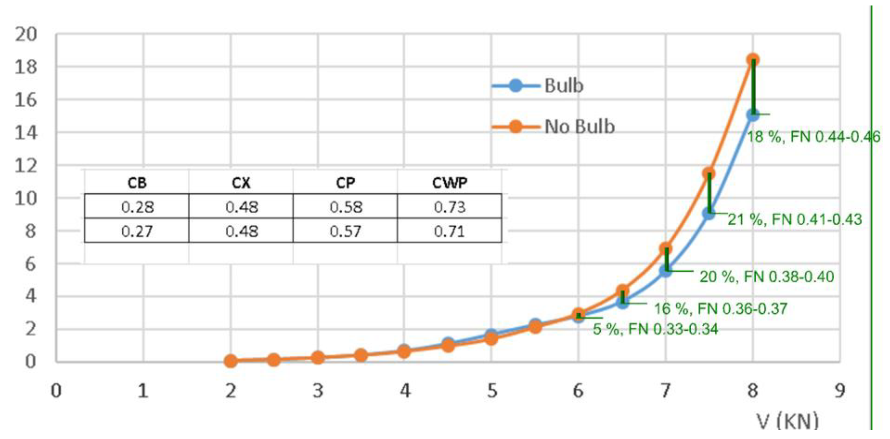
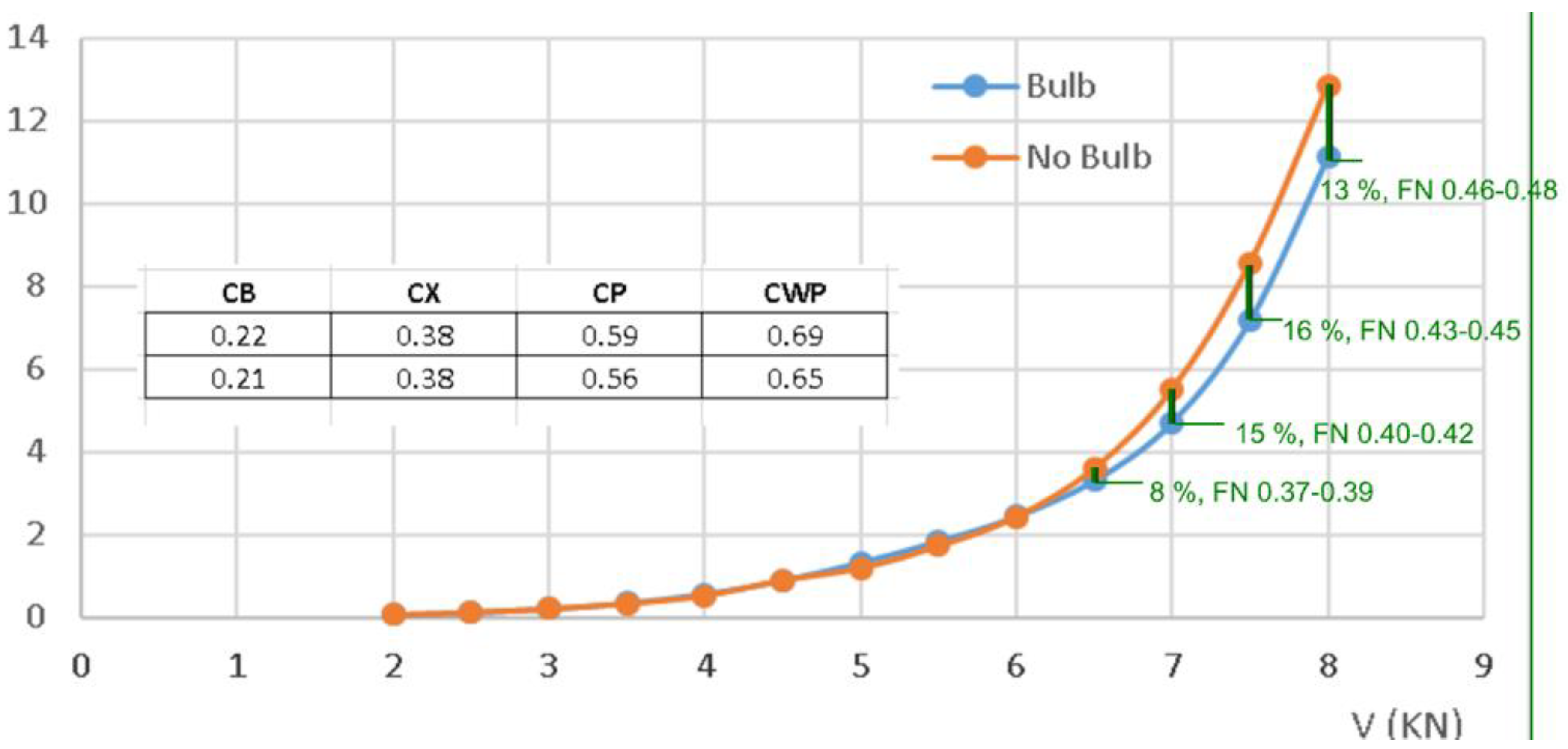
With Cts coefficient, the resistance of the ship (full scale) can be computed and by multiplying this force by the speed in m/s, the effective power (PE) is obtained. In the following figures, the PE is compared between the original hulls (FAO1 and FAO3) and the modified ones that include a dihedral bow (FAO2 and FAO4). Each figure includes a chart that contains the hull form coefficients. The coefficients of the top row of the chart correlate to the ship without the dihedral bow, with a lower LWL that produces higher coefficient values.
Figure 17, Figure 18, Figure 19, Figure 20 and Figure 21 show also the Froude number Fr = Speed/(9.81·LWL)^0.5 of both options, with the higher Froude number associated with the ship without the dihedral bow, since LWL is lower.
Form coefficients and Froude numbers are useful to compare these four designs with other designs that may present equivalent form coefficients. This way, a number associated with the power reduction is available when installing a dihedral bow.
The Reynolds number in the test was inside [9.5 × 10⁵~3.8 × 10⁶] for FAO1 and FAO2, and inside [4.4 × 10⁵~4.1 × 10⁶] for FAO3 and FAO4.
The results of FAO1 vs FAO2 (displacement hull) demonstrate there is a PE maximum reduction of about 20% for the higher displacement speeds, about Fr = 0.4, where dynamic effects begin. Reduction is lower over this Fr. This behavior is common both for heavy and light conditions, but for light conditions, the maximum reduction is about 16%.
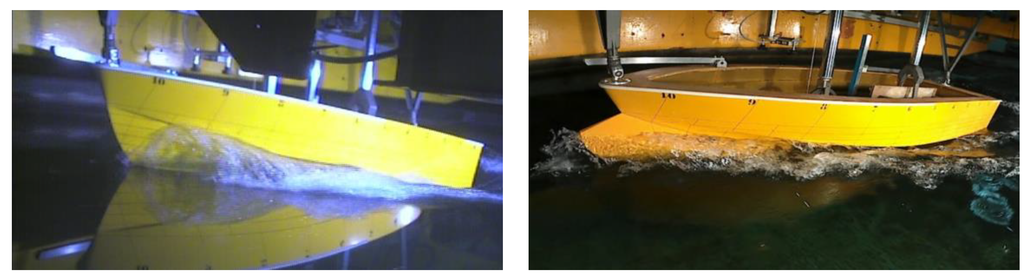
For light conditions, the positive effect of the dihedral bow starts above Fr = 0.35. Below this Fr, the PE is not reduced because of the increment in wet surfaces of the dihedral bow. A comparison of the tests can be seen in Figure 19 for FAO1_2 at Fr = 0.43, which has a reduction of 21% in the PE for heavy conditions. The dihedral bow diminishes the waves that the hull produces by diffracting the water.
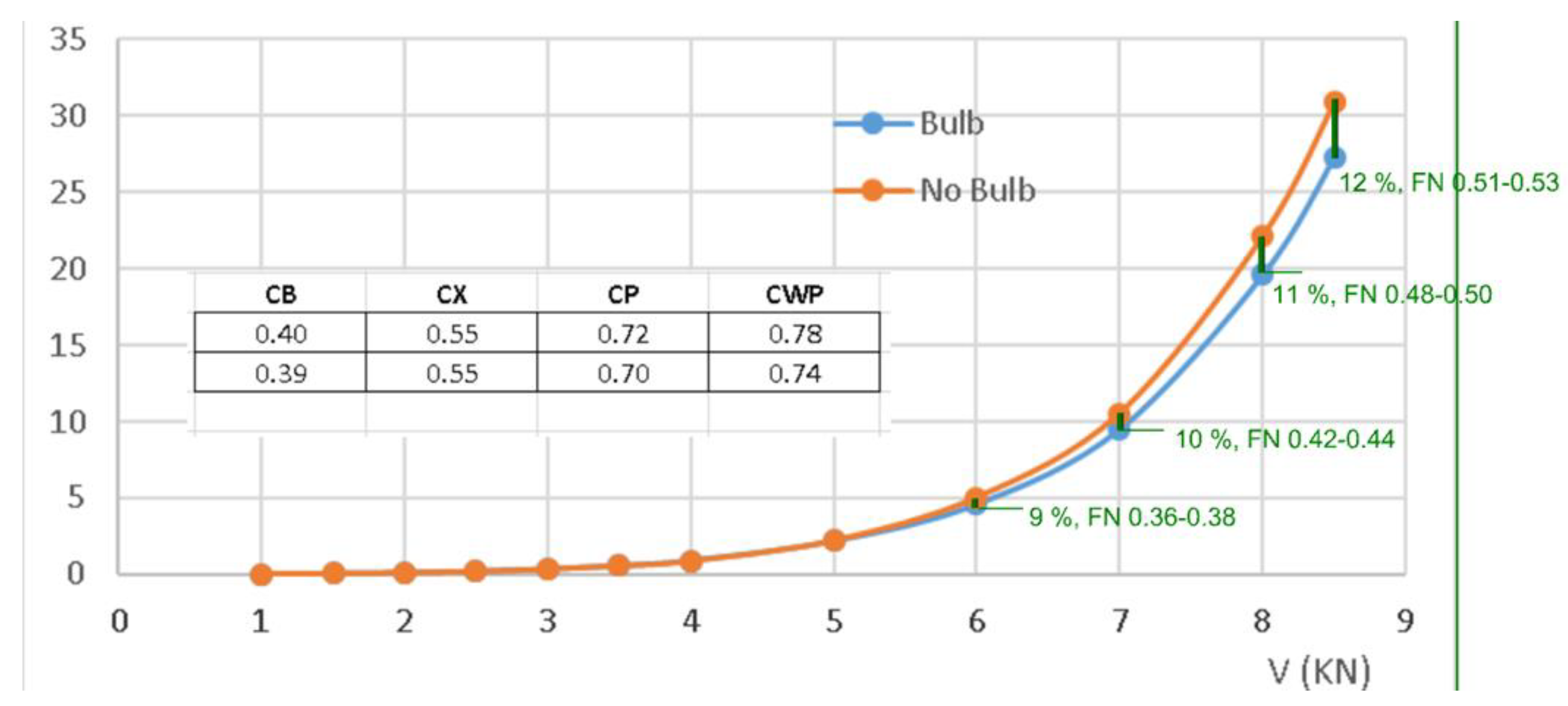
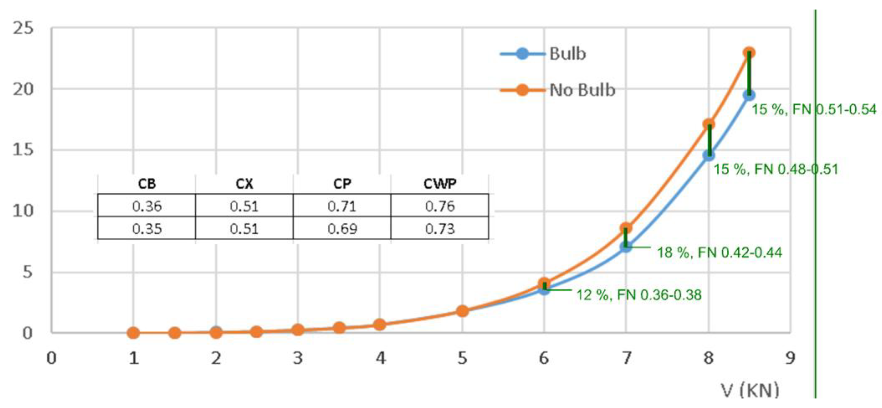
The results of FAO3 vs FAO4 (Semi Displacement hull) demonstrate the maximum reduction is 18% for Fr about 0.4 in the displacement hull, see Figure 21. In this hull, this reduction is obtained for light conditions, while the maximum reduction in heavy conditions is 12% for the high Fr values, Figure 20. As in the hull previously discussed, the positive effect starts over Fr = 0.35.
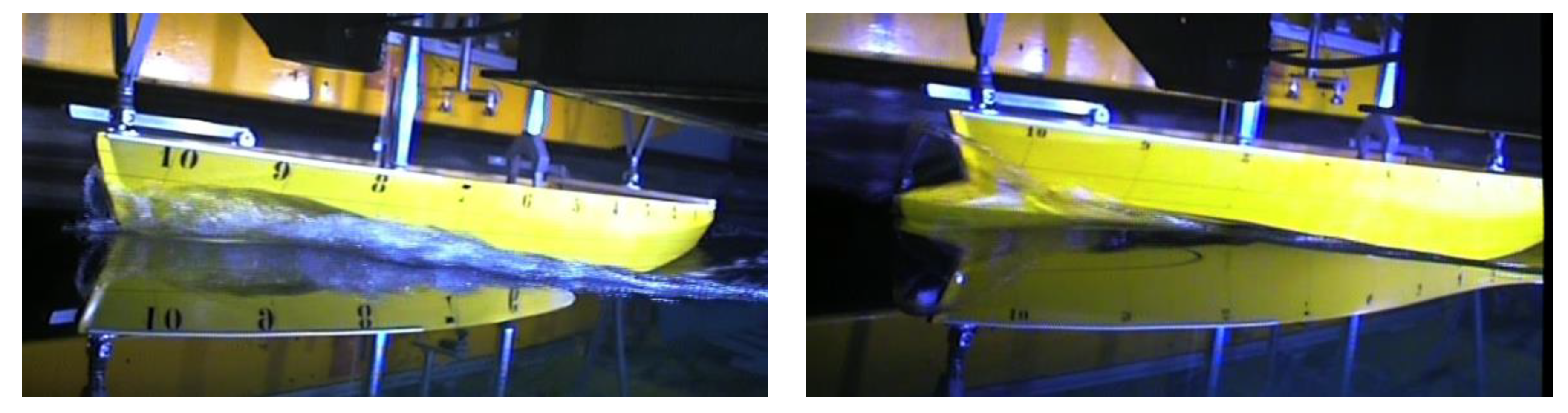
In the case of FAO3_4, a comparison can be seen in Figure 22 for Fr = 0.51, which has a reduction of 12% for heavy conditions. The dihedral bow diminishes the waves and also reduces the trim angle, as explained in the next section.
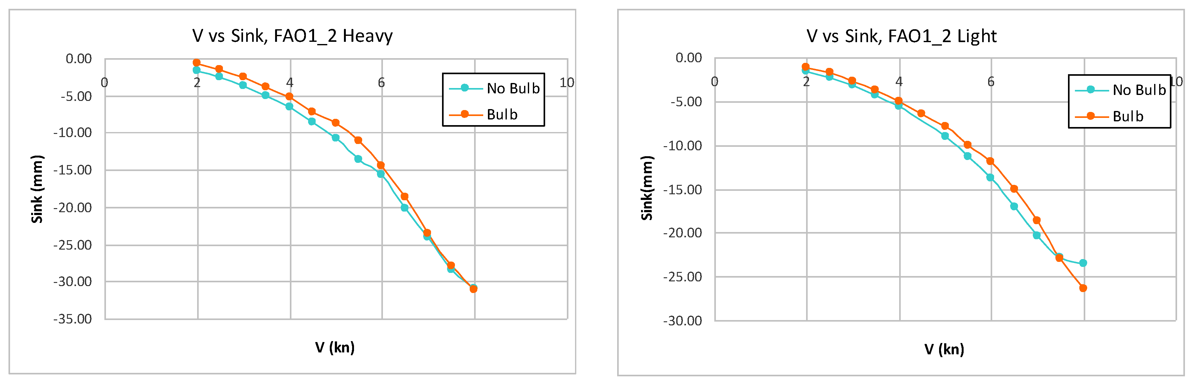
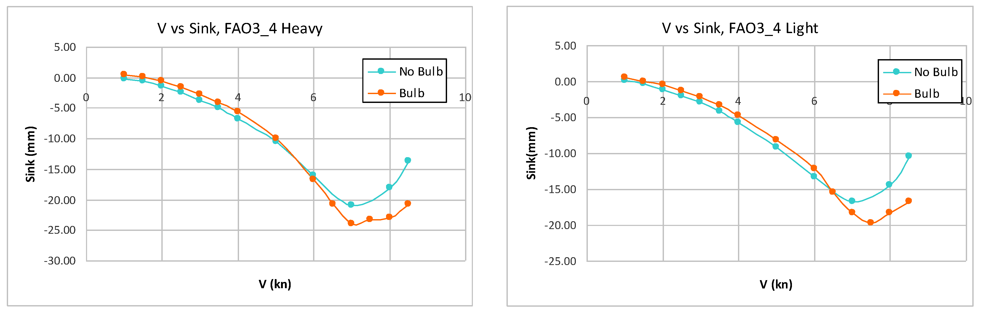
5. Experimental Results on Sinkage and Trim Angle
The dihedral bow changes the dynamic sinkage and trim of the ships by deflecting the water flow into the original hull, which changes the pressure distribution over the hull. The effect on sinkage is presented in Figure 23 and Figure 24. For lower speeds, the effect of the dihedral bow results in a slight reduction of the sinkage. This reduction is maintained in both heavy and light conditions. For semi-planing speeds, demonstrated in Figure 24, the sinkage is higher with the dihedral bow. In this figure, the dynamic effect can be seen on the sinkage curves near planing speeds, where the sinkage decreases as the speed is increased due to dynamic effects that lift the hull.
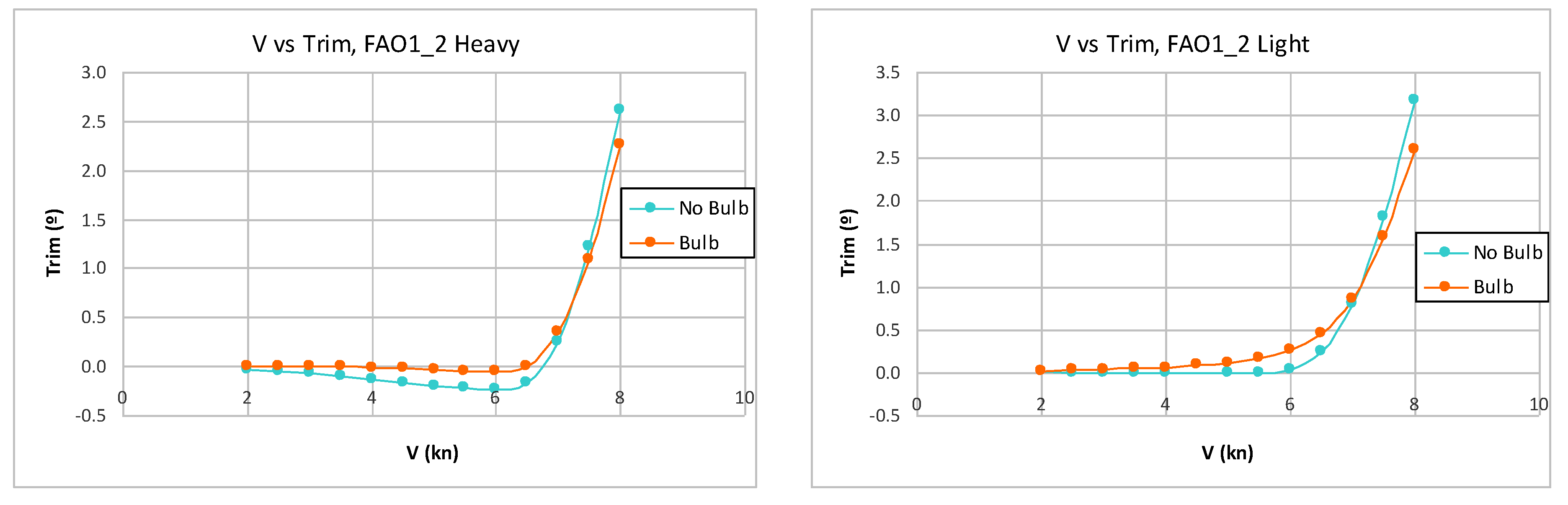
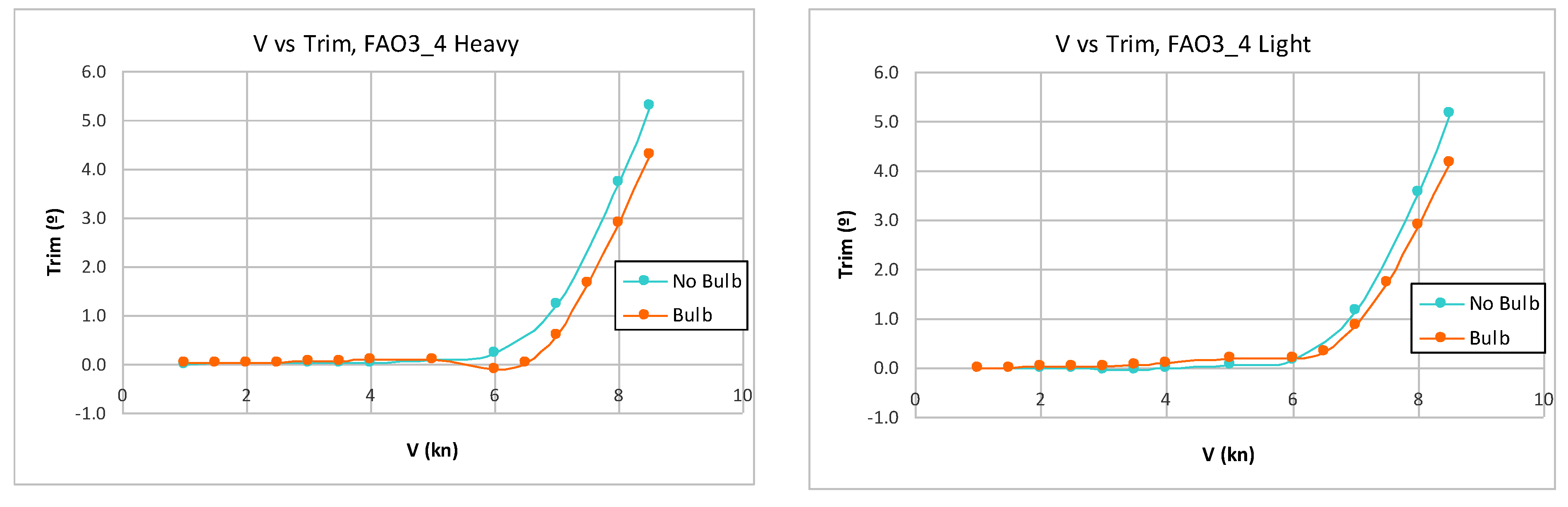
The effect of the dihedral bow on the trim angle can be seen in Figure 25 and Figure 26. Negative values of the trim angle indicate the bow was down, and positive values indicate the bow was up and the stern was down. The dihedral bow produces a slight trim increase for low speeds and a trim reduction for higher speeds. This tendency is consistent in both heavy and light conditions. The reduction in the trim angle suggests improved performance of the ships at high speeds.
6. Conclusions
This research has presented a new type of developable added bulbous bow: the dihedral bow. It is formed by two developable surfaces and can be installed as an added bulbous bow that intersects the original hull geometry with a knuckle curve. This dihedral bow acts as a piercing beak bow, diffracting the water and producing a reduction of the PE that the ship requires.
The first step is to consider the design of three master curves or directrices named K (Keel), C (Chine) and T (Top curve). When these curves have been defined, the rulings that define the developable surfaces can be traced following the methodology in [2]. This method takes into consideration the properties of the material (aluminum, steel, wood, etc.).
These directrices may or may not follow the original ship chine and keel, depending on the shape of the original hull. The shape depends also on the loading condition since the dihedral bow must pierce the waterplanes of different conditions in order to maintain an optimal design. Therefore, a standard design methodology is not easy to develop.
This research has presented towing tank tests for two dihedral bows that are compared with the respective original hulls under two loading conditions. The hulls are of the displacement and semi-displacement variety, and in both loading conditions, the dihedral bow produced an important reduction in the PE of the ships, with the consequent reduction in fuel consumption and pollution.
The hydrodynamic effects of the dihedral bow is a diffraction of the water when approaching the hull and a reduction in the dynamic trim.
The maximum PE reduction depends on the loading condition and is higher in the case of the displacement hull (FAO1_2: about 21% heavy) than in the case of the semi-displacement hull (FAO2_4: about 18% light). The hulls tested have a free and open geometry and belong the FAO database, which was created to provide fishing resources in developing countries by defining different ship designs.
Of minor importance on resistance, but with a high impact on comfort aboard, the dihedral shape reduces the spray because the water is deflected away from the hull in its C line. A good design of a dihedral bow together with a balanced design of the hull and correct positioning of the center of gravity can produce an efficient boat when compared with a ship without a bulbous bow.
The advantages of the dihedral bow are very promising, and continued study of dihedral bows is pertinent to share the results in an open journal with the scientific and engineering community.
7. Future Work
Studying ships that could be defined entirely with developable surfaces began in 2017. FAO1 and FAO3 can be fully defined this way. Authors have explored other options of developable surfaces that can be defined containing curves, which resulted in the development of dihedral bows, which are based in the polyhedral and Pantocaréne hulls presented in the introduction.
Today, we are working with CFD (Computational Fluid Dynamics) techniques to study and validate the experiments and the numerical calculations. As a result, new designs can be created without experimental tests, and further analysis can be made with the numerical techniques, such as pressure distribution and flow analysis, which are not easy to do experimentally.
Another line of research is the application of dihedral bows to round bilge hulls (without knuckle lines). The authors expect promising results in these types of hulls and anticipate exploring and designing them with numerical techniques.
Although dihedral bows were originally designed for small vessels, like thos available in the FAO database, the authors intend to study these bows for larger ships. A promising example is the Thanon di Revel Class [16] constructed by Fincantiery, Figure 27. This navy ship includes a polyhedral bow, has an Lpp of 133 m and, with the available public information, estimated form coefficients are CB of 0.27 and Fr = 0.45, which enters the range of form coefficients where the dihedral bow has shown optimal results.
Author Contributions
F.P.-A.: Conceptualization, Software, Design, Analysis, Writing original draft and reviews. A.S.-C.: Conceptualization, Structural Calculations, Analysis, Writing original draft and reviews. H.R.D.-O.: Conceptualization, validation, Analysis, Writing original draft. All authors have read and agreed to the published version of the manuscript.
Funding
This work was initially supported by the Spanish “Ministerio de Economía y Competitividad” through research grant TRA2015-67788-P.
Institutional Review Board Statement
Not applicable.
Informed Consent Statement
Not applicable.
Data Availability Statement
Not applicable.
Acknowledgments
Juan Luis Chacón from ETSIN Model Basin, who was the key person in the experimental tests. Raymon VanAnrooy from FAO (NFIFO) who supervised the FAO data base. Thanks to Adriana Oliva.
Conflicts of Interest
The authors declare no conflict of interest.
References
- FVDD. FAO Vessels Design Database. Available online: https://www.fao.org/fishery/en/vesseldesign/search (accessed on 1 September 2022).
- Pérez-Arribas, F.; Silva-Campillo, A.; Díaz-Ojeda, H.R. Defining developable ship surfaces considering material properties. Ocean. Eng. 2022, 243, 110164. [Google Scholar] [CrossRef]
- Kracht, A.M. Design of bulbous bows. SNAME Trans. 1978, 86, 197–217. [Google Scholar]
- Yim, B. A simple design theory and method for bulbous bows of ships. J. Ship Res. 1974, 18, 141–152. [Google Scholar] [CrossRef]
- Yim, B. Simple calculation on sheltering effect on ship wave resistance and bulbous bow design. J. Ship Res. 1980, 24, 232–243. [Google Scholar] [CrossRef]
- Szelangiewiczz, T.; Abramowskizz, T.; Żelazny, A.; Sugalski, K. Reduction of Resistance, Fuel Consumption and GHG Emission of a Small Fishing Vessel by Adding a Bulbous Bow. Energies 2021, 14, 1837. [Google Scholar] [CrossRef]
- Blanchard, L.; Berrini, E.; Duvigneau, R.; Roux, Y.; Mourrain, B. Bulbous Bow Shape Optimization. In Proceedings of the 5th International Conference on Computational Methods in Marine Engineering, Hamburg, Germany, 29–31 May 2013. [Google Scholar]
- Thai, G.T.; Chinh, V.H.; Hyun Cheol, K. Optimal design method of bulbous bow for fishing vessels. Int. J. Nav. Archit. Ocean. Eng. 2021, 13, 858–876. [Google Scholar]
- Larrie, D.F. The Social History of the Bulbous Bow. In Technology and Culture; Johns Hopkins University Press: Baltimore, ML, USA, 2011; Volume 52, pp. 335–359. [Google Scholar]
- Barrass, B. Ship Design and Performance for Masters and Mates; Elsevier: Amsterdam, The Netherlands, 2004; ISBN 9780080454948. [Google Scholar]
- Chrismianto, D.; Kim, D.J. Parametric bulbous bow design using the cubic Bezier curve and curve-plane intersection method for the minimization of ship resistance in CFD. J. Mar. Sci. Technol. 2014, 19, 479–492. [Google Scholar] [CrossRef]
- Pérez, F.; Suárez, J.; Clemente, J.; Souto-Iglesias, A. Geometric modelling of bulbous bows with the use of non-uniform rational B-spline surfaces. J. Mar. Sci. Technol. 2007, 12, 83–94. [Google Scholar] [CrossRef]
- FAO1 Definition. Available online: https://www.fao.org/fishery/en/vesseldesign/nir-1 (accessed on 1 September 2022).
- FAO3 Definition. Available online: https://www.fao.org/fishery/en/vesseldesign/bvi-07 (accessed on 1 September 2022).
- ITTC 2017: Recommended Procedure Guidelines: Resistance and Propulsion Tests and Performance Prediction with Skin Friction Drag Reduction Techniques. Available online: https://www.ittc.info/media/9603/75-02-02-03.pdf (accessed on 1 September 2022).
- Thaon di Revel. Available online: https://en.wikipedia.org/wiki/Thaon_di_Revel-class_offshore_patrol_vessel (accessed on 1 September 2022).
Figure 1.
Examples of polyhedral bulbous bows. (https://commons.wikimedia.org/wiki/Category:Polyhedral_bows (accessed on 1 September 2022)).
Figure 1.
Examples of polyhedral bulbous bows. (https://commons.wikimedia.org/wiki/Category:Polyhedral_bows (accessed on 1 September 2022)).

Figure 2.
Pantocaréne Hull (www.bairdmaritime.com (accessed on 1 September 2022)).
Figure 2.
Pantocaréne Hull (www.bairdmaritime.com (accessed on 1 September 2022)).

Figure 3.
Geometric definition of a polyhedral Bulbous Bow.

Figure 4.
Example of curves; T curve inside the hull.

Figure 5.
Example of curves; T curve over the hull.

Figure 6.
Obtaining a developable surface.

Figure 7.
Rulings in a dihedral bow.

Figure 8.
Example 1 lines drawing (FAO1), LOA = 9.22 m, BOA = 3.00 m.

Figure 9.
Rulings for the dihedral bow of example 1 (FAO2).

Figure 10.
Unrolled dihedral bow of FAO2.

Figure 11.
Comparison between FAO1 and FAO2 geometry.

Figure 12.
Example 2 line drawings (FAO3), LOA = 7.62 m, BOA = 2.97 m.

Figure 13.
Rulings for the dihedral bow of example 1 (FAO4).

Figure 14.
Unrolled dihedral bow of FAO4.

Figure 15.
Comparison between FAO3 and FAO4 geometry.


Figure 16.
Transverse view of Tank at ETSIN and power test setup.

Figure 17.
Power reduction for FAO1 vs. FAO2, heavy conditions.

Figure 18.
Power reduction for FAO1 vs. FAO2, light conditions.

Figure 19.
FAO1 vs. FAO2 at 7.5 kn, Heavy condition.

Figure 20.
Power reduction for FAO3 vs. FAO4, heavy conditions.

Figure 21.
Power reduction for FAO3 vs. FAO4, light conditions.

Figure 22.
FAO3 vs. FAO4 at 8.5 kn, heavy conditions.

Figure 23.
Effect on sinkage, FAO1 vs. FAO2.

Figure 24.
Effect on sinkage, FAO3 vs. FAO4.

Figure 25.
Effect on trim, FAO1 vs. FAO2.

Figure 26.
Effect on trim, FAO3 vs. FAO4.

Figure 27.
Paolo Thaon di revel ship with a polyhedral bow. https://www.armadainternational.com/2019/07/italian-navy-launches-paolo-thaon-di-revel/ (accessed on 1 September 2022).
Figure 27.
Paolo Thaon di revel ship with a polyhedral bow. https://www.armadainternational.com/2019/07/italian-navy-launches-paolo-thaon-di-revel/ (accessed on 1 September 2022).


Table 1.
Parameters for the models, heavy conditions.
| SHIP | Disp(kg) | T(m) | Slenderness | Alfa (°) | CB | CX | CP | CWP |
|---|---|---|---|---|---|---|---|---|
| FAO1 | 6404 | 0.98 | 4.5 | 25 | 0.28 | 0.48 | 0.58 | 0.73 |
| FAO2 | 6755 | 0.98 | 4.8 | 15 | 0.27 | 0.48 | 0.57 | 0.71 |
| FAO3 | 5489 | 0.68 | 3.9 | 35 | 0.40 | 0.55 | 0.72 | 0.78 |
| FAO4 | 5787 | 0.68 | 4.2 | 25 | 0.39 | 0.55 | 0.70 | 0.74 |
Table 2.
Parameters for the models, light conditions.
| SHIP | Disp(kg) | T(m) | Slenderness | Alfa (°) | CB | CX | CP | CWP |
|---|---|---|---|---|---|---|---|---|
| FAO1 | 3627 | 0.81 | 4.9 | 24 | 0.22 | 0.38 | 0.59 | 0.69 |
| FAO2 | 3926 | 0.81 | 5.4 | 12 | 0.21 | 0.38 | 0.56 | 0.65 |
| FAO3 | 3974 | 0.58 | 4.3 | 33 | 0.36 | 0.51 | 0.71 | 0.76 |
| FAO4 | 4203 | 0.58 | 4.6 | 25 | 0.35 | 0.51 | 0.69 | 0.73 |
Publisher’s Note: MDPI stays neutral with regard to jurisdictional claims in published maps and institutional affiliations. |
© 2022 by the authors. Licensee MDPI, Basel, Switzerland. This article is an open access article distributed under the terms and conditions of the Creative Commons Attribution (CC BY) license (https://creativecommons.org/licenses/by/4.0/).
Share and Cite
MDPI and ACS Style
Pérez-Arribas, F.; Silva-Campillo, A.; Díaz-Ojeda, H.R. Design of Dihedral Bows: A New Type of Developable Added Bulbous Bows—Experimental Results. J. Mar. Sci. Eng. 2022, 10, 1691. https://doi.org/10.3390/jmse10111691
AMA Style
Pérez-Arribas F, Silva-Campillo A, Díaz-Ojeda HR. Design of Dihedral Bows: A New Type of Developable Added Bulbous Bows—Experimental Results. Journal of Marine Science and Engineering. 2022; 10(11):1691. https://doi.org/10.3390/jmse10111691
Chicago/Turabian StylePérez-Arribas, Francisco, Arturo Silva-Campillo, and Héctor Rubén Díaz-Ojeda. 2022. "Design of Dihedral Bows: A New Type of Developable Added Bulbous Bows—Experimental Results" Journal of Marine Science and Engineering 10, no. 11: 1691. https://doi.org/10.3390/jmse10111691
Note that from the first issue of 2016, this journal uses article numbers instead of page numbers. See further details here.