
Abstract
An experimental investigation of low-speed flow actuation at near-atmospheric pressure is presented. The flow actuation is achieved via low-current ( 1.0 mA) continuous or pulsed DC surface glow discharge plasma. The plasma actuator, consisting of two sharp-edged nickel electrodes, produces a tangential flow in a direction from anode to cathode, and is visualized using high-speed schlieren photography. The induced flow velocity estimated via the schlieren images reaches up to 5 m/s in test cases. The actuation capability increases with pressure and electrode gap distances, and the induced flow velocity increases logarithmically with the discharge power. Pulsed DC exhibits slightly improved actuation capability with better directionality. An analytic estimation of induced flow velocity obtained based on ion momentum in the cathode sheath and gas dynamics in one-dimensional flow yields values similar to those measured.
Export citation and abstract BibTeX RIS
1. Introduction
The use of gas discharge plasma covers a wide range spanning from the semiconductor industry to the biomedical industry. One of these branches lies in aerospace applications, encompassing plasma thrusters,1,2) magnetohydrodynamic power generation,3,4) and plasma-assisted combustion enhancement.5,6) Aerodynamic flow control, as in separation control, lift enhancement, and drag reduction, has been studied for more than a century and is still an attractive field in fluid dynamics research, with the aim of attaining a practically-applicable flow control mechanism. Recent studies of aerodynamic flow control show increasing dependence on plasma-based techniques. The primary driving force of the plasma flow actuator is ion collision with neutral gas particles. The collision produces a wave which is a local disturbance and changes a local pressure to induce a flow. A unique feature of the plasma flow actuator is the generation of direct force in a bulk-flow region above the solid surface, while mechanical actuators deliver momentum only through the surface. The plasma flow actuator can provide a slip boundary condition without moving mechanical parts. Various types of plasma actuators have been developed for flow control. A recent review by Moreau7) provides a broad spectrum of flow control techniques using the plasma actuator from early stages to present technology.
The single dielectric barrier discharge (SDBD) plasma actuator is among the most widely-studied plasma actuators, and is used extensively for aerodynamic applications including boundary-layer attachment,8–10) lift enhancement,11,12) and drag reduction.13) Recent applications of the SDBD actuator include a pressure sensor,14) enhanced convection heat transfer,15) and noise control.16,17) Closed-loop control of the SDBD plasma flow actuator is currently under investigation,18,19) an important aspect in practical flow-control technique. The SDBD is generally created using a symmetric sinusoidal voltage of several kilovolts, operating at several kilohertz. The discharge structure is, however, asymmetric for each half cycle due to the SDBD's asymmetric geometry, where one of the electrodes is exposed while another is embedded under dielectric material. For this reason, the functional stage varies from glow discharge to streamer-dominant discharge when the negative half cycle switches to a positive half cycle.20) This produces asymmetric forcing which is experimentally measured via a vertical pendulum. The positive-going cycle produces a pushing effect 3% of that provided by the negative-going cycle, resulting in a net pushing effect.21) The asymmetric forcing in the SDBD plasma actuator is also observed in accelerometer measurements.22) This observation provides important insight into SDBD plasma flow control, in that a conversion of small pushing into large pushing can improve the performance of the SDBD plasma actuator. One practical approach is to add a DC component to the SDBD actuator.23) The unidirectional force is enhanced with a DC shift. Span-wise and stream-wise non-uniformity in the SDBD structure can also cause a non-uniform force due to the streamers generated spatially and temporally at random over an entire span.
Due to the intrinsic low-velocity characteristics of the SDBD, its application to practical flow situations is limited, and performance improvements are required. In order to further increase the actuation capability of the SDBD plasma actuator, nanosecond pulsed-discharge is being studied, by which the possibility of efficient flow actuation at a free-stream flow velocity of 100 m/s is shown.24) The primary actuation source in a nanosecond pulse-discharge is the rapid heating of gas near the aerodynamic surface, in contrast to conventional SDBD plasma actuators, where the primary actuation source is the direct transfer of linear momentum to neutral atoms accomplished by ions. As a result, the effect on flow actuation due to turbulent mixing is strong in boundary layers, even though the induced flow velocity of nanosecond pulse-discharge is nearly zero.
In this paper, a DC discharge plasma actuator on a flat plate is studied to understand the flow actuation mechanism and to provide the idea to overcome the asymmetric forcing of SDBD. DC discharge utilizes one or more of the three flow actuation mechanisms of gas heating, electrostatic force, and electromagnetic force. Without an external magnetic field, the electromagnetic force is not applicable, while the gas-heating and electrostatic force occur simultaneously. Gas heating is responsible for a buoyancy effect and is predominantly achieved in two ways, Joule heating (J · E, where J is the current density and E is the electric field) driven by ion or electron collision with neutrals, and surface heating driven by ion collision with the surface. If the discharge current increases, we expect the gas heating to also increase. When the gas heating effect is low, an increased electrostatic force is also achieved, which is responsible for directional gas flow. In this study, we focus on the electrostatic force rather than the gas-heating effect in order to provide an induced flow in a specific direction.
DC discharge plasma actuators in subsonic flow can be divided into two types, the corona discharge plasma actuator and the glow discharge plasma actuator. Figure 1 shows an illustration of the discharge structure in both corona and glow discharge. Typical corona discharge actuators consist of a sharp-edged anode and a flat cathode. An ion flow is produced near the anode from the strong electric field at the anode, which results in a net positive charge. The ions then move towards the cathode through a relatively weak electric field.25,26) This ion flow produces bulk gas motion called an "ion wind". DC glow discharges have typical structures including a positive column and a cathode sheath.27) The positive column exhibits a weak electric field between anode and cathode. The cathode sheath exhibits a strong electric field near the cathode where most ionization occurs, and produces a net positive charge near the cathode. Electrostatic force in the glow discharge is driven primarily in the cathode sheath region. The electron and ion density are similar in the bulk plasma region between anode and cathode, due to the quasi-neutral nature of the glow discharge, resulting in no significant net force. Though ion mass exceeds electron mass, the net force in a collision with neutrals is similar due to the higher mobility of electrons. In the case where a strong ionization occurs near the anode region, the expectation is that the ion wind originates from the anode. Note that in DC discharge, the flow actuation can be obtained via net positive space charge, which can produce a net force on neutrals. Advantage of using DC discharge for flow actuation is the ability to provide an actuation effect at the desired location and time. It is also possible to take advantage of pulsed discharge, which can reduce the buoyancy effect of the DC discharge and control linear momentum transfer to neutrals by changing the pulse duty cycle. The DC discharge applied in this report operates at low current levels ( 1 mA), which can be energy efficient for a required flow actuation capability and can reduce Joule heating that assists the buoyancy effect. Time-resolved, high-speed schlieren images of induced flow field will be provided in order to understand the flow structure obtained via low-current DC discharge. Analytic estimation of induced flow velocity is attempted using Child's sheath law and gas dynamics equations. This paper emphasizes the flow actuation capability of low-current DC surface glow discharge and the mechanisms of electrostatic force which drive ions in a cathode sheath, supported by analytic estimation of the force.

Fig. 1. Schematic drawing and photo image of the DC surface glow discharge plasma actuator: (a) corona discharge and (b) surface glow discharge.
Download figure:
Standard image High-resolution image2. Experiment methods
2.1. DC surface-glow-discharge plasma actuator
Figure 2 shows a schematic configuration of the plasma actuator and photo images of the DC surface-glow discharge. The actuator consists of three pairs of sharp-edged nickel electrodes that are exposed to ambient air. The electrode pairs are glued to a flat mica dielectric using epoxy, and are then cleaned with methanol. The separation between two adjacent electrode pairs is 4 mm, and several electrode gap distances of 1, 2.5, and 5 mm were tested. By using a point electrode for both anode and cathode, a location of high-pressure plasma formation and hence ion path can be properly controlled. At large electrode gap distances, the discharge begins to form between one anode and two cathodes by connecting the discharge along two cathodes. At lower pressures, the glow discharge between electrodes begins to bend away from the surface.

Fig. 2. Illustration of electrostatic forcing near the cathode sheath and bulk plasma regions, produced by surface glow discharge.
Download figure:
Standard image High-resolution image2.2. Electrical configuration
Both continuous DC and pulsed DC power are used in this study to provide the required potential drop to the plasma actuator. The power supply used was capable of providing continuous DC voltage and current up to 10 kV and 20 mA, respectively. Each pair of electrodes is individually ballasted with 10–20 MΩ resistors connected in series with each cathode to maintain a uniform discharge. This process limits the discharge current to a maximum of approximately 2 mA. Up to three pairs of electrodes are turned on simultaneously. As the ballast resistance decreases, the discharge current increases and the power consumed by the discharge increases. In addition, higher current DC discharge tends to produce more surface and gas heating near the cathode region, promoting the buoyancy effect. The discharge current through each electrode pair is calculated by measuring the voltage drop across a 1 kΩ resistor connected downstream of each ballast resistor. For pulsed DC operation, an in-house pulse generator that switches the continuous DC voltage on and off at a desired frequency is connected in series with the resistors just before a ground. An actuator is placed inside a chamber that can provide a controlled stagnant condition at the desired pressures. Three air pressures of 101.3 kPa (760 Torr), 66.7 kPa (500 Torr), and 40.0 kPa (300 Torr) were used for this study.
2.3. Schlieren imaging
A high-speed schlieren imaging system was used to visualize the induced flow field and to estimate the propagation speed of the flow. A high-power (>900 mW) red LED (Prizmatix UHP-Microscope-LED-630) provided continuous light for the schlieren imaging. Two bi-convex lenses were used to focus the light from the LED source in order to obtain a point source; the focused beam was then collimated by a concave mirror with a focal length of 1.2 m. A vertical knife edge was used to increase sensitivity in the stream-wise direction (from anode to cathode), parallel to the actuator surface. A high-speed CMOS camera (Photron Fastcam SA3 120 K) mounted with a 300 mm focal length lens was used to take the schlieren images of the induced-flow field. The repetition rate and shutter speed of the camera was adjusted such that the moment of initiation of induced flow could be captured. The induced-flow velocity was estimated by measuring the pixel displacement of the wave front between two consecutive schlieren images.
3. Flow actuation characteristics
Figure 3 shows a close-up view of time-resolved, sequential schlieren images when the induced flow was initiated by one pair of plasma actuators in a stagnant air pressure of 101.3 kPa. The gap distance between anode and cathode was 5 mm, and a discharge current of 0.3 mA was continuously provided, resulting in a discharge power of 1.23 W. The frame rate of schlieren imaging is 5 kHz and the shutter speed is 1/20,000 s. The t = 0 in Fig. 3(a) corresponds to the frame just before the flow is detected in the schlieren image. As shown in Fig. 3(b), the compressed region (brighter area) formed a wave front near the cathode, followed by a corresponding expansion region (darker area) that stretched to the anode. As the frame continues, the wave front propagates to the left, clearly indicating that the induced flow is more or less tangent to the actuator surface in the direction from anode to cathode. The dotted line in the bottom image [Fig. 3(e)] approximately marks the integrated area of the perturbed region swept by the wave. Time-resolved, sequential schlieren images taken from hundreds of test runs with similar conditions reveal that the wave front generally begins near the cathode region and propagates over the cathode surface, implying that the actuation effect is stronger near the cathode area than near the anode, and hence that flow actuation is not dominantly driven by the ion wind effect generated near the anode, as is the case with corona-discharge plasma actuators. In Fig. 3, the induced flow speed reaches approximately 4.3 m/s, which is estimated by measuring the pixel displacement of the wave front between Figs. 3(b) and 3(c). The magnitude of the induced flow speed is in a comparable range with that of a SDBD28) or corona actuator.29) The actuation capability increases with the electrode gap distance for the same set-point current. With a larger gap, the initial propagation speed is higher and the perturbed region is larger at a specific time after the initiation of flow. As the electrode gap distance increases, the discharge voltage required to ignite and sustain the plasma increases. A higher voltage drop increases the electric field near the cathode, which in turn produces a stronger actuation effect. It is important that the ion path remains parallel to the actuator surface.

Fig. 3. Time-resolved sequential schlieren images of induced tangential flow directed from anode to cathode. The dotted line approximately marks the integrated perturbed area where the brighter compression region propagates to the left, followed by the darker expansion region. The discharge current is set at a constant 0.3 mA.
Download figure:
Standard image High-resolution imageIt was observed in the schlieren images that a low-current continuous DC glow discharge can generate a tangential flow on a flat plate; though the actuation effect needs improvement in order to apply the plasma actuator in an actual flowing condition. A larger number of electrode pairs are required for larger area flow actuation. Figure 4 shows the effect of increased numbers of electrode pairs on induced flow velocity at three pressures. The error bars represent 95% confidence intervals, which are evaluated assuming that statistical errors follow the Student's t-distribution (a continuous probability distribution), used when the sample size is small and the population standard deviation is unknown.30) The same error scheme will be used for the plots hereafter. The electrode gap distance is 5 mm, and the separation between each pair is 4 mm. The discharge current is set at a constant 0.5 mA. The induced flow velocity for the two-pair case shows similar values to the single-pair case for each pressure; however, the induced flow velocity exhibits increase for all pressures in the three-pair case in comparison to the other two cases. The actuation source becomes two-dimensional (2D) with a larger number of electrode pairs, owing to a decrease in the 3D relieving effect produced by the individual electrode pair. It can also be seen that the induced flow velocity increases with ambient pressure. As the ambient pressure increases, the discharge voltage increases due to a collisional loss in electron energy at higher pressures. In addition, the voltage drop occurs within a shorter distance due to a narrower sheath thickness, hence creating a stronger electric field near the cathode that is proportional to the electrostatic force.

Fig. 4. The effect of pressure and increasing numbers of electrode pairs on induced flow velocity. The discharge current is set at a constant 0.5 mA in each case.
Download figure:
Standard image High-resolution imageThe actuation capability can also be improved by increasing the discharge power, which is done by raising the discharge current. The power consumption for the single electrode pair case with a glow discharge at the same set-point current of 0.5 mA is shown in Fig. 5. As the gap distance increases at fixed pressure, the voltage drop required for gas breakdown increases due to a higher Paschen breakdown minimum at a larger pressure–distance (p–d) value.31) The discharge power increases with pressure for a fixed gap distance, as previously described. At a fixed gap distance and pressure, the discharge power increases predominantly with current. The induced flow velocities at various discharge powers are presented in Fig. 6. The discharge power is raised by increasing the discharge current. The electrode gap distance is 5 mm, and only one electrode pair is turned on. As shown in the figure, the induced flow velocity increases as the discharge power increases; however, the increment of increase is smaller as the discharge power increases at each pressure, exhibiting a logarithmic increase. As the DC current increases, the ion Joule heating effect also increases near the cathode region where the strong electrostatic flow actuation is expected to occur. Cathode heating is also expected due to ion impact on the surface. This heating effect in turn increases the buoyancy effect, which degrades the directional motion tangential to the actuator surface. The result shown in Fig. 6 indicates an efficient operational regime that yields optimal actuation performance.

Fig. 5. Variation of power consumed by the DC surface glow discharge, with various electrode gaps at different pressures. The discharge current is set at a constant 0.5 mA in each case.
Download figure:
Standard image High-resolution image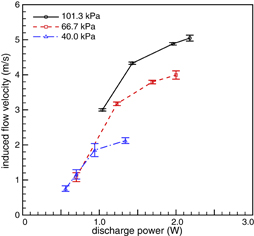
Fig. 6. Induced flow velocity estimated via high-speed schlieren images at various discharge powers. The gap distance between electrodes is 5 mm in all cases, and one pair of electrodes is turned on.
Download figure:
Standard image High-resolution imageFigure 7 shows the effect of pulsed DC on induced flow velocity at various discharge conditions. The heating effect resulting from DC glow discharge can be weakened by applying pulsed DC. The pulse duty cycle was set at 50% with a pulse frequency of 5 kHz, and the discharge current was set to a constant value of 0.3 mA for all cases. The dashed line corresponds to continuous DC, and the solid line corresponds to pulsed DC. Pulsed DC generally exhibits higher average induced velocity, except in low-pressure cases with 2.5 mm electrode spacing. However, when the cycle averaged power is considered, the actuation efficiency (actuation capability per unit power) achieved via pulsed DC is significantly higher than that via continuous DC in every case. The schlieren image reveals that the directionality of the induced flow is slightly improved with pulsed DC discharge due to the reduced heating, in turn resulting from the replenishment of air occurring between pulses. Pressure recovery between current pulses is also expected to play a role in the mechanism of pushing and pulling air.
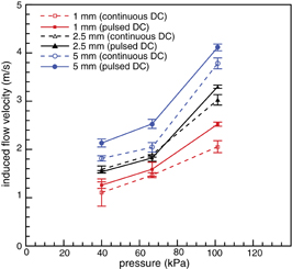
Fig. 7. The effect of pulsed DC on induced flow velocity. The pulse duty cycle is 50%, and the pulse frequency is 5 kHz. The solid and dashed lines correspond to pulsed and continuous DC, respectively. A single electrode pair is turned on, and the discharge current is set to a constant 0.3 mA in all cases.
Download figure:
Standard image High-resolution image4. Analytic estimation of induced flow velocity
We estimate the induced flow velocity by assuming that the forcing is largely due to an ion pressure force produced in the cathode sheath region, as illustrated in Fig. 1. Due to a steep electric field near the cathode, electrons move quickly away from the cathode surface. The density of ions in the cathode sheath region is larger compared to that of electrons, as the negatively-charged cathode attracts ions leading to a net-positive charge. Ion pressure drops as it approaches the cathode owing to the acceleration of ions in the cathode sheath. This produces a net ion pressure gradient in the direction from cathode to anode, driving a bulk gas flow towards the cathode. Assuming the electrons are absent in the cathode sheath, the ion continuity equation is as follows:

where ns and us are the ion number density and ion drift velocity at the sheath edge, respectively. The current density at the sheath edge is determined by the ion density at the sheath edge, as follows:

Hence, ion density in the sheath is
Here, the ion drift velocity is assumed to be dominated by the mobility of ions in the presence of the electric field,

Poisson's equation describes the relation between the electric field and space charge density as

The 1D form gives
Assuming the electric field at the sheath edge is zero, because the most of the voltage drop occurs in the cathode sheath in DC discharge, the integration of Eq. (6) gives
Integrating again with E = −dV/dx and the boundary conditions of V(ts) = Vc and V(0) = 0, the sheath thickness becomes
The ion momentum equation in the collisional sheath can be approximated by considering the dominant terms of ion pressure gradient and electrostatic force, ∇Pi = eniE. The total ion pressure change in one dimensional flow is estimated as
The induced flow velocity can be estimated via a simple gas dynamics analysis. In the stagnant gas condition, a small pressure pulse (ΔPi) induces flow at a given velocity (v + dv). Ignoring gravity and the viscous effect, the one-dimensional, compressible flow velocity produced by weak pressure change can be obtained as follows: Euler's equation of motion for steady one dimensional inviscid flow is

where vs is the speed of sound ( ), γ is the specific heat ratio, R is the gas constant, and T is the local temperature. Note that the positive increment of velocity in stagnant air is produced by a negative pressure change. Thus Eq. (10) can be written as ΔPi = ρvsΔv. Using the ideal gas law, the velocity increment can be calculated as32)

where P is the local pressure. From Eqs. (8), (9), and (11), we can calculate the values of the cathode sheath thickness, pressure change in the sheath, and induced flow velocity, respectively.
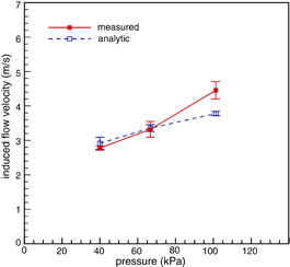
For a typical discharge with a 0.5 mA set-point current and 2.9 kV of applied voltage at one atmosphere (P = 101,325 Pa, T = 288.15 K), the cross-sectional area is measured at 7.9 × 10⁻⁹ m2 based on the discharge image, which in turn gives the current density J0 = (0.5 × 10⁻³)/(7.9 × 10−9) = 6.3 × 10⁴ A/m2. The background gas in air plasma is assumed to be nitrogen, which has an ion mobility (μi) of 9 × 10⁻³ m2 V−1 s−1. Inputting these values in Eqs. (8) and (9), the cathode sheath thickness (ts) is calculated at 2.3 × 10⁻⁴ m, and the pressure change (ΔPi) across the cathode sheath at 1.6 kPa. Entering these values into Eq. (11), the induced flow velocity (Δv) is estimated at 3.8 m/s. Figure 8 shows a comparison between the analytically-estimated (dotted line) and experimentally-measured (solid line) values of induced flow velocity at three pressures. The experimental data are taken from the one pair, 5 mm case of Fig. 4. As shown in Fig. 8, the analytic estimation of induced flow velocity predicts magnitudes similar to experimentally-measured values for the pressure range where the majority of the low-speed aerodynamic application is expected. This result supports the idea that the flow actuation in this work is dominantly due to ions generated near the cathode sheath, as described in the introduction.
Fig. 8. A comparison of analytically-estimated flow velocity (hollow square) with experimentally-measured values (solid square). One pair of electrodes is turned on in the experimental cases. Experimental data are taken from the one pair, 5 mm case shown in Fig. 4.
Download figure:
Standard image High-resolution image
5. Conclusions
Tangential flow observed through high-speed schlieren imaging was produced by a sharp-edged DC surface glow discharge plasma actuator operating at very low current ( 1.0 mA). The discharge structure exhibited a streak-like discharge, where a narrow glow discharge stretched from anode to cathode. A weak pressure wave, a combination of the compression and expansion regions, is visualized through schlieren imaging. The induced flow velocity estimated via propagation of the weak pressure wave showed a logarithmic increase in conjunction with the discharge power. The maximum induced flow velocity for the presented cases was estimated to reach values as high as 5 m/s, with 2 W of discharge power at one atmosphere. These values are comparable to those obtained via SDBD plasma or corona actuators. The actuation capability increased with the number of electrode pairs and electrode gap distance. Pulsed DC discharge promoted flow actuation by reducing the gas heating effect produced by DC discharge. Since the discharge current used in this paper was very low, the Joule heating effect was also expected to be low. The electrostatic force was estimated by assuming that the driving force was predominantly generated by ions in the cathode sheath. An analytic estimation of sheath thickness, ion pressure change, and induced flow velocity showed similar velocity magnitudes to those obtained experimentally via schlieren images. Based on this correlation, it is reasonable to assume the aerodynamic flow actuation achieved by DC glow discharge is dominated by ions generated in the cathode sheath. This remark was partly supported by the high-speed schlieren images, where initiation of flow mostly occurred near the cathode region rather than near the anode region.
Acknowledgement
This work was supported by the 2012 Special Research Fund of Mechanical Engineering at the University of Ulsan.