
Abstract
We studied the magnetic domain wall (DW) creep motion in two driving forces: external magnetic field and spin Hall torque (SHT). The dimensional crossover from two to one dimension is identified by looking at the distribution width of the DW velocity depending on the wire width. The distribution widths are found to be similar regardless of the driving forces in narrow wires, whereas they show nonnegligible differences depending on the driving force in wide wires. Therefore, the dimensional crossover implies that the effective magnetic field induced by the SHT becomes equivalent to the external magnetic field only when the wire is considered as one-dimensional.
Export citation and abstract BibTeX RIS
Magnetic domain wall (DW) motion in a ferromagnetic nanowire is an essential phenomenon for both scientific interests and potential applications for information technology beyond semiconductor-based electronics.1–9) In particular, DW creep motion, which is known as thermally activated DW motion observed in disordered media, has been intensively studied over the last decade to improve the reliability of device operation.10–17) In the creep regime, the interaction between driving forces and disorders gives rise to the universality class of the DW motion.10,14,16,17) It has been reported that both the field- and current-driven (based on the spin transfer torque) DW motions exhibit the universality class transition in a dimension of a nanowire.14,17) The elucidation of such a dimensional transition is important since the transition from two to one dimension occurs at a few hundred nanometers, corresponding to the integration scale for modern nanodevices.
Recently, a new type of DW driving mechanism by a combination of the spin-Hall torque (SHT) and the Dzyaloshinskii–Moriya interaction (DMI) has been observed in nanowires with ferromagnet/heavy-metal structures.18–23) Owing to the spin Hall effect, a pure spin current is generated in the heavy-metal layer and injected into the ferromagnetic layer. On the other hand, the DMI energetically favors the Néel DW. Since the injected spin is orthogonal to the magnetization direction within the Néel DW, the DW consistently receives a torque that drives its translational motion. Several pioneering works have pointed out that this new mechanism can bring out highly efficient DW-based memory devices.19–21) However, its dimensional characteristic has not been clarified yet. In this Letter, we experimentally demonstrate the dimensional transition from two to one dimension for the SHT-driven DW motion. Velocity distribution is investigated for various wire widths to identify the dimensional crossover. The distribution widths are found to increase with decreasing wire width and saturate below a threshold width. The saturation of the distribution width is found to originate from the dimensional transition from two to one dimension. The result is compared with the magnetic-field-driven case. The distribution widths for two driving forces are found to be similar in narrow wires (one-dimensional case), whereas they show a nonnegligible difference in wide wires (two-dimensional case). This result indicates that the effective magnetic field induced by the SHT is equivalent to the external magnetic field only when the wires are considered as one-dimensional.
The thin-film structure of magnetic wires was Ta (4 nm)/Pt (2 nm)/MgO (1 nm)/Co (0.3 nm)/Ni (0.6 nm)/Co (0.3 nm)/Pt (2 nm)/Ta (4 nm)/Si, prepared by dc magnetron sputtering. The MgO layer between the Co and upper Pt layers was inserted to provide structural inversion asymmetry so that SHT drives the Néel-type DW.21–23) A perpendicular magnetic anisotropy (Ku) of 1.31 × 10⁶ J/m3 and a saturation magnetization (Ms) of 8.37 × 10⁵ A/m were measured using a superconducting quantum interference device magnetometer (not shown here). The DW velocity was determined by an anomalous Hall measurement illustrated in the inset of Fig. 1. The wires were fabricated by electron beam lithography and Ar ion milling. The wire width w was varied from 100 nm to 3 µm.

Fig. 1. Typical Hall resistance measurement for magnetic-field-driven DW motion. The Hall resistance is normalized from the M–H curve. (Inset) Schematic illustration of typical device structure with measurement setup.
Download figure:
Standard image High-resolution imageFigure 1 shows the plots of the normalized Hall resistance ( ) versus the elapsed time (t). The DW was introduced by injecting a current pulse (88 mA for 40 ns) via electrode A (shown in the inset of Fig. 1), then driven by a magnetic field or a current. When the DW arrived at the Hall cross at a certain time, named the DW arrival time (tarrival), an abrupt increase in
  was observed owing to the magnetization switching at the center of the Hall cross. Since the DW in the creep regime shows stochastic motion, tarrival is different in each measurement with the same strength of a driving force for DW motion, as pointed by red arrows in Fig. 1 as a reference. DW velocity (v) was estimated by measuring tarrival. We repeated the above measurement 300–500 times to obtain the distribution of DW velocity.
Figure 2 shows the v distributions of DW motion driven by a magnetic field or SHT in 1-µm- and 100-nm-wide wires. In the case of the 1-µm-wide nanowire, the SHT-driven DW motion showed a much broader distribution than the field-driven one. This is because the SHT gives rise to a nonuniform torque on localized spins in the DW, whereas the magnetic field uniformly does it as we previously reported.23) In contrast, the distributions of both the field-driven and SHT-driven DW velocities are comparable to each other in the 100-nm-wide wire. This result indicates that there is another considerable factor related to the wire width that is important in understanding the SHT-driven DW motion behavior in the creep regime.
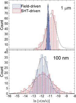
Fig. 2. DW velocity distribution for magnetic-field- (blue) and SHT- (red) driven DW creep motions in 1-µm- (upper graph) or 100-nm- (lower graph) wide wire. The distributions are obtained from 500 (1 µm) and 300 (100 nm) repeated measurements. The black lines are the fitting lines obtained using Eq. (1).
Download figure:
Standard image High-resolution imageFor the quantitative investigation of the distribution, we fit the velocity distribution using the following Gaussian function:
Here, y0 is the offset, xc is the distribution center, which is a peak position, d is the standard deviation, and A is the area. The fitted lines are presented in Fig. 2. The full width at half maximum (FWHM) of the fitting curve can be defined as  , which indicates the broadness of the distribution. The FWHMs for both magnetic-field- and SHT-driven DW motions are plotted as a function of
  in Fig. 3(a). Here,
  is required for a statistical analysis because the DW stochastically moves along the wire in the creep regime. The FWHM sharply increased to
  , then saturated in both field- and current-driven DW motions. This behavior cannot be explained by the different driving forces for different wire widths, because the FWHM does not critically depend on the driving force in the creep regime.23) All of the data in Fig. 3(a) were obtained in the velocity range from 10−6 to 10−5 m/s, which certainly belongs to the creep regime. Furthermore, the FWHMs of both cases became comparable to each other when
  . This means that there is a critical width for the transition of the DW motion behavior in the Co/Ni nanowire.

Download figure:
Standard image High-resolution image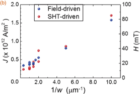
Fig. 3. (a) FWHM as a function of  when a DW is driven by a magnetic field (blue symbols) or SHT (red symbols). The error bars are the fitting errors using Eq. (1). The different colored areas correspond to the different dimensional regimes. (b) Driving current density and propagation magnetic field as functions of 1/w. J is the current density flowing through the bottom Pt layer, which is estimated from the sheet resistance measurement.
Download figure:
Standard image High-resolution imageThe DW is generally considered as a stringlike object composed of multiple segments in the creep regime. Therefore, the DW motion can be characterized by the random motion of multiple segments originating from the pinning potentials in the wire. We can simplify this situation as a biased random walk having a population of N in the wire width direction and having the number of steps (M) in the wire length direction. Therefore, the total number of trials in the DW motion can be N × M. Here, N can be defined as the number of DW segments along the wire width, that is, N = w/wcol with the characteristic DW segment length (wcol), and M can be the number of pinning events in the wire length direction. This simple model predicts that the distribution of DW motion is proportional to  when w is the same as wcol or over. For w < wcol, only a single DW segment exists in the nanowire, such that the distribution becomes saturated. This is analogous to the dimensional crossover of DW velocity as reported in Ref. 14. To quantitatively define the dimensional crossover, wcol is defined as
  , where Lc is the Larkin length and Hcrit is the critical field at zero temperature.11,24) It is estimated as
  nm for our field range and is consistent with the present experiment. Here, we assumed Lc = 50 nm and used Hcrit = 200 mT, which is experimentally determined by the temperature dependence of the DW depinning field.
The distribution reflects the interactions between the pinning sources and the driving forces (magnetic field or SHT). Thus, it is required to classify the pinning potential in the wire. Quenched disorders inside the nanowire, originating from the local anisotropy variation due to nonuniform film growth, contribute to the FWHM. We denote the contribution as σin. In addition, the fabricated nanowires practically have edge roughness whose effect would be significant in narrow wires. This pinning potential of the edge roughness also contributes to the FWHM, which we denote as σedge in this study. Figure 4 schematically illustrates the DW motion induced by the field and SHT in the presence of two pinning sources, namely, quenched disorders and edge roughness. The domain wall is expected to have a zigzag shape during the motion as we proved in our previous study.23) The schematic image in Fig. 4 intuitively shows how the domain wall can be affected by the pining potentials. It shows that the pinning mechanism can be gradually changed by decreasing the wire width. When w > wcol, σin can be dominant owing to the small edge effect. In this case, the FWHMs significantly depend on the type of driving force owing to the two-dimensional (2D) characteristic of the DW, as we addressed in our previous work.23) As w < wcol, σedge becomes dominant over σin. In this case, the distribution is predominantly determined by σedge. Therefore, both field- and SHT-driven DW motions are equally affected by edge roughness in this regime. Such a transition in the pinning mechanism can be supported by measuring the DW motion in each driving force. Figure 3(b) shows the driving current density J and propagation field H as functions of 1/w. Here, J and H are respectively defined as the current density and magnetic field that we used in the experiment for moving the DW. Since all the measurements were performed in similar velocity ranges (10−6–10−5 m/s), the linear dependence indicates that the edge effect gradually increases when the wire width is decreased.25,26) Thus, the saturation value of FWHM in a narrow wire is mostly dependent on σedge. It is worthwhile to note that the different trends between Figs. 3(a) and 3(b) imply that Joule heating is not the origin of the saturation of the FWHM with the narrowing of the wire since the effect of Joule heating continuously increases with decreasing wire width owing to the increasing driving current density.27)

Fig. 4. Schematic illustration of DW creep motion driven by a magnetic field and the SHT with decreasing wire width. Circles in the nanowire denote the quenched disorders originating from the film growth.
Download figure:
Standard image High-resolution image
Lastly, we comment on the effect of driving forces on the FWHM. In the case of wide wires (w > wcol), the FWHMs in both the field-driven and SHT-driven cases are apparently different from each other: the FWHM in the SHT-driven case is much larger than that in the field-driven case. This is caused by the 2D DW characteristic, which has a large flexure structure that senses a nonuniform SHT.23) In the case of narrow wires (w < wcol), however, the saturation value of FWHM is similar in the magnetic field and SHT cases [Fig. 3(a)]. This remarkably underlines the fact that the effective magnetic field induced by the SHT becomes equivalent to the external field in such one-dimensional wires owing to the absence of a DW flexure structure (Fig. 4).
In conclusion, we found that the distribution of the DW velocity exhibits a dimensional transition from two to one dimension with decreasing wire width. The difference in DW velocity distribution in the current-driven and field-driven cases becomes negligible when the wire is narrower than wcol, below which a one-dimensional characteristic of DW motion appears. This dimensional transition implies that an effective magnetic field induced by the SHT can be regarded as an external magnetic field only in the wires, which is considered as one-dimensional.
Acknowledgments
This work was partly supported by a Grant-in-Aid for Scientific Research (S), a Grant-in-Aid for Scientific Research (C), a Grant-in-Aid for Young Scientists (B), a Grant-in-Aid for Scientific Research on Innovative Areas, the Collaborative Research Program of the Institute for Chemical Research, Kyoto University, and the R&D Project for ICT Key Technology of MEXT.
Note added in proof—After submission of this manuscript, we found that similar work was published [J. Kim, S.-G. Je, and S.-B. Choe, Appl. Phys. Express 8, 063001 (2015)].